WEG CFW-11 User Manual
Hide thumbs
Also See for CFW-11:
- Programming manual (291 pages) ,
- Installation manual (212 pages) ,
- User manual (145 pages)

Related Manuals for WEG CFW-11


Summary of Contents for WEG CFW-11
- Page 1 Motors | Energy | Automation | Coatings Frequency Inverter Convertidor de Frecuencia Inversor de Freqüência CFW-11 User's Guide Manual del Usuario Manual do Usuário...
- Page 2 FREQUENCY INVERTER MANUAL Series: CFW-11 Language: English Document: 10000280997 / 00 Models: 142...211 A / 220...230 V 105...211 A / 380...480 V 03/2009...
- Page 3 Summary of Revisions Revision Description Chapter First Edition...
-
Page 4: Table Of Contents
CHAPTER 2 General Instructions 2.1 About the Manual ........................2-1 2.2 Terms and Definitions ........................2-1 2.3 About the CFW-11 ........................2-4 2.4 Identification Labels for the CFW-11 .....................2-7 2.5 Receiving and Storage ......................2-10 CHAPTER 3 Installation and Connection 3.1 Mechanical Installation .......................3-1 3.1.1 Installation Environment .....................3-1... - Page 5 Index CHAPTER 4 KEYPAD AND DISPLAY 4.1 Integral Keypad - HMI-CFW11 ....................4-1 4.2 Parameters Organization ......................4-4 CHAPTER 5 First Time Power-Up and Start-Up 5.1 Prepare for Start-Up ........................5-1 5.2 Start-Up .............................5-2 5.2.1 Password Setting in P0000 ....................5-2 5.2.2 Oriented Start-up ......................5-3 5.2.3 Setting Basic Application Parameters ...................5-5 5.3 Setting Date and Time .........................5-8 5.4 Blocking Parameters Modification ....................5-8...
-
Page 6: Safety Warnings In The Manual
Safety Instructions SAFETY INSTRUCTIONS This manual provides information for the proper installation and operation of the CFW-11 frequency inverter. Only trained and qualified personnel should attempt to install, start-up, and troubleshoot this type of equipment. 1.1 SAFETY WARNINGS IN THE MANUAL... -
Page 7: Preliminary Recommendations
NOTE! For the purpose of this manual, qualified personnel are those trained and able to: 1. Install, ground, power-up, and operate the CFW-11 according to this manual and to the current legal safety procedures; 2. Use the protection equipment according to the established regulations;... - Page 8 The other manuals are provided on the CD supplied with the product. This CD should be retained with this equipment at all times. A hard copy of this information may be ordered through your local WEG representative.
- Page 9 Safety Instructions...
-
Page 10: General Instructions
E models. It is also possible to operate the CFW-11 in the following control modes: V V W, Sensorless Vector and Vector with Encoder. For further details on the inverter operation with other control modes, refer to the Software Manual. - Page 11 HMI - Human Machine Interface: it is a device that allows the motor control, and the visualization and modification of the inverter parameters. The CFW-11 HMI presents keys for the motor command, navigation keys and a graphic LCD display.
- Page 12 General Instructions PLC: Programmable Logic Controller. °C: Celsius degree. °F: Fahrenheit degree. AC: Alternated Current. Amp, A: Ampères. CFM: Cubic Feet per Minute; unit of flow. cm: Centimeter. DC: Direct Current. ft: Foot. hp: Horse Power = 746 Watts; unit of power, used to indicate the mechanical power of electrical motors. Hz: Hertz.
-
Page 13: About The Cfw-11
General Instructions 2.3 ABOUT THE CFW-11 The CFW-11 frequency inverter is a high performance product designed for speed and torque control of three- phase induction motors. The main characteristic of this product is the “Vectrue” technology, which has the following advantages: Scalar control (V/f), V V W, or vector control programmable in the same product;... - Page 14 Digital Outputs DO1 (RL1) to DO3 (RL3) (*) The RFI filter capacitor against the ground must be disconnected with IT and grounded delta networks. Refer to the section 3.2.3.1.1 for more details. Figure 2.1 - Block diagram for the CFW-11...
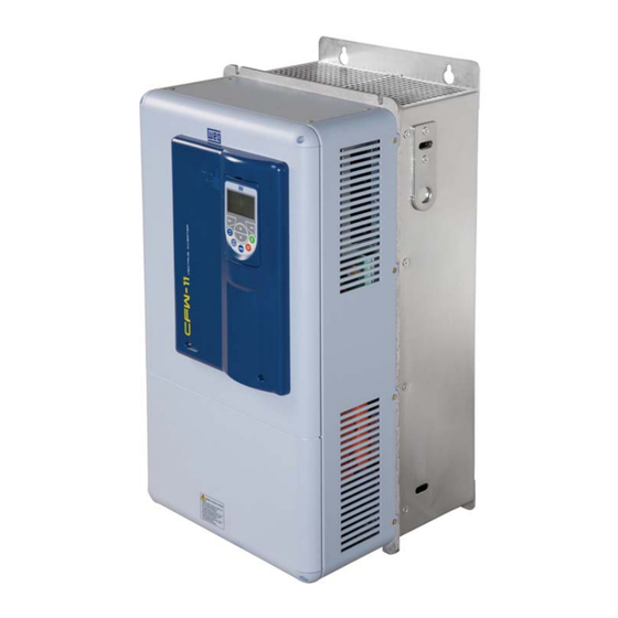
- Page 15 K – Rear part of the inverter (external part for flange mounting) L – SRB2 Safety stop board M – Nema1 kit top cover (“hat”) N – Nema1 kit bottom (Conduit kit) Figure 2.2 - Main components of the CFW-11...
-
Page 16: Identification Labels For The Cfw-11
2.4 IDENTIFICATION LABELS FOR THE CFW-11 There are two nameplates on the CFW-11: one complete nameplate is affixed to the side of the inverter and a simplified one is located under the keypad. The nameplate under the keypad allows the identification of the most important characteristics of the inverter even if they are mounted side-by-side. - Page 17 General Instructions Nameplate affixed to the side of the heatsink Nameplate under the keypad Figure 2.5 - Location of the nameplates...
- Page 18 General Instructions...
-
Page 19: Receiving And Storage
Report any damage immediately to the carrier that delivered your CFW-11 inverter. If CFW-11 is to be stored for some time before use, be sure that it is stored in a clean and dry location that conforms to the storage temperature specification (between -25 °C and 60 °C (-13 °F and 140 °F)). Cover the inverter to prevent dust accumulation inside it. -
Page 20: Installation And Connection
Installation and Connection INSTALLATION AND CONNECTION This chapter provides information on installing and wiring the CFW-11. The instructions and guidelines listed in this manual shall be followed to guarantee personnel and equipment safety, as well as the proper operation of the inverter. - Page 21 Installation and Connection ATTENTION! When arranging two or more inverters vertically, respect the minimum clearance A + B (figure 3.2) and provide an air deflecting plate so that the heat rising up from the bottom inverter does not affect the top inverter. ATTENTION! Provide conduit for physical separation of the signal, control, and power conductors (refer to item 3.2 - Electrical Installation).
- Page 22 Installation and Connection Model (in) (in) (in) (in) CFW11 0142 T 2 (3.94) (5.12) (1.57) CFW11 0180 T 2 (5.91) (9.84) (3.15) CFW11 0211 T 2 (0.78) CFW11 0105 T 4 (3.94) (5.12) (1.57) CFW11 0142 T 4 CFW11 0180 T 4 (5.91) (9.84) (3.15)
-
Page 23: Cabinet Mounting
Installation and Connection 3.1.3 Cabinet Mounting There are two possibilities for mounting the inverter: through the wall mounting or flange mounting (the heatsink is mounted outside the cabinet and the cooling air of the power module is kept outside the enclosure). The following information shall be considered in these cases: Surface assembly: Provide adequate exhaustion so that the internal cabinet temperature is kept within the allowable operating... -
Page 24: Installation Of The Inverter Hoisting Eyes
Installation and Connection Figure 3.3 - Repositioning the mounting supports 3.1.4 Installation of the Inverter Hoisting Eyes Two hoisting eyes for the inverter lifting, which are mounted at the inverter sides (rear part), are supplied. By inverting their position, as showed in the figure 3.4, 2 points for hoisting the inverter, which are very useful during the mechanical installation of the inverter, are obtained. -
Page 25: Installation Of The Inverter With Nema1 Kit (Optional, Cfw11Xxxxtxon1) On A Wall
Installation and Connection 3.1.5 Installation of the Inverter with Nema1 Kit (Optional, CFW11XXXXTXON1) on a Wall Fixing holes position and diameter according to the figure 3.1. External dimensions of the inverter with Nema1 kit according to the section 8.4. Fasten the inverter. Install the Nema1 kit top on the inverter as showed in the figure 3.5 using the 2 M8 screws supplied with the product. - Page 26 Installation and Connection In order to get access to the power terminal block, the bottom front cover must be removed, as showed in the figure 3.7. Figure 3.7 - Bottom front cover removal At the CFW11 0180 T 2 O N1, CFW11 0211 T 2 O N1, CFW11 0180 T 4 O N1 and CFW11 0211 T 4 O N1 inverters (supplied with Nema1 kit), it is also necessary to remove the front cover of the Nema1 kit bottom part in order to be able to execute the power section electric installation –...
-
Page 27: Removal Of The Cable Passage Plate
Installation and Connection 3.1.7 Removal of the Cable Passage Plate When it is not necessary neither IP20 nor Nema1 protection degree, the cable passage plate may be removed in order to make the inverter electric installation easier. Remove the 4 M4 screws, according to the procedure presented in the figure 3.9. -
Page 28: Electrical Installation
DC-: this is the negative potential terminal in the DC bus circuit. DCL+: positive pole of the rectifier output voltage. DCL-: negative pole of the rectifier output voltage. Ground (4xM8, 4xM5) Figure 3.11 - Power terminals and grounding points of the CFW-11 series frame size E models... -
Page 29: Power / Grounding Wiring And Fuses
(U/T1, V/T2, or W/T3). - Check all the connections before powering up the inverter. - In case of replacing an existing inverter by a CFW-11, check if the installation and wiring is according to the instructions listed in this manual. - Page 30 Installation and Connection Table 3.2 - Recommended Wire size/ Fuses - use only copper wire [75 ºC (167 °F)] Power terminal Wire size Over- Fuse Fuse Bolt Recommended Model load Terminals (wrench/screw torque Terminals class head type) N.m (lbf.in) R/L1,S/L2,T/L3, M8 (hexagonal U/T1,V/T2,W/T3, 15 (132.75)
- Page 31 Installation and Connection Table 3.3 (a) - Recommended cable lugs for power connections (cable gauges in mm²) Wire size Number of Stud size Manufacturer Ring lug, P/N Crimping (installation) tool P/N crimps Hollingsworth RM 25 -5 H 6.500 Tyco 33468 59975-1 Hollingsworth RM 25-8...
- Page 32 Installation and Connection Table 3.3 (b) - Recommended cable lugs for power connections (cable gauges in AWG) Wire size Number of [AWG/ Stud size Manufacturer Ring lug, P/N Crimping tool P/N crimps kcmil] Hollingsworth R 410 H 6.500 Dieless tool: MY29-3 or Y644 or Y81; Burndy (FCI) YA4CL2 Tool+U-die: Y46 or Y35 or Y750 / U4CRT...
-
Page 33: Power Connections
(U, V, W). AC power supply considerations The CFW-11 inverters are suitable for use on a circuit capable of deliviering up to a maximum of 100,000 A symmetrical (230 V / 480 V). -
Page 34: It Networks
3.2.3.1.1 IT Networks ATTENTION! In order to be able to use the frame size E CFW-11 inverter in IT networks (neutral conductor not grounded or grounded via a high ohmic value resistor) or in corner-grounded delta systems, it is necessary to remove the RFI filter capacitor and the MOV connected to the ground by changing the position of the J1 jumper on the PRT1 board from (XE1) to “NC”, according to the figure 3.13. -
Page 35: Command Fuses
3.2.3.2 Dynamic Braking ATTENTION! For the CFW-11 frame size E models, only those with the DB option (CFW11XXXXTXODB) have the braking IGBT incorporated to the product. The braking torque that can be obtained from the frequency inverter without braking resistors varies from 10 % to 35 % of the motor rated torque. -
Page 36: Sizing The Braking Resistor
For critical applications with very short deceleration times and high inertia loads (ex.: centrifuges) or short duration cycles, consult WEG for the adequate sizing of the braking resistor. -
Page 37: Installation Of The Braking Resistor
3.14. CFW-11 Contactor... -
Page 38: Output Connections
When several motors are connected to the same inverter, install individual overload relays for each motor. ATTENTION! The motor overload protection available at the CFW-11 is in accordance with the IEC60947-4-2 and UL508C standards. Important considerations for the UL508C: Trip current equal to 1.25 times the motor rated current (P0401) adjusted in the oriented start-up... - Page 39 Installation and Connection Keep motor cables away from other cables (signal cables, sensor cables, control cables, etc.), according to table 3.5. The grounding system shall be well interconnected among the several installation locations such as the grounding points of the motor and the inverter. Voltage difference or impedance between the several points may cause the circulation of leakage currents among the equipment connected to the ground, resulting in electromagnetic interference problems.
-
Page 40: Grounding Connections
- To comply with IEC 61800-5-1 standard, connect the inverter to the ground by using a single conductor copper cable with a minimum wire gauge of 10 mm , since the leakage current is greater than 3.5 mA AC. CFW-11 #1 CFW-11 #2 CFW-11 #N CFW-11 #1... -
Page 41: Control Connections
Installation and Connection 3.2.5 Control Connections The control connections (analog inputs/outputs, digital inputs/outputs), shall be performed in connector XC1 of the CC11 control board. Functions and typical connections are presented in figures 3.18 (a) and (b). Connector XC1 Factory Default Function Specifications Positive reference for Output voltage:+5.4 V, ±5 %. - Page 42 Installation and Connection Connector XC1 Factory Default Function Specifications Positive reference for Output voltage:+5.4 V, ±5 %. +REF potentiometer Maximum output current: 2 mA Analog input #1: Differential AI1+ Speed reference (remote) Resolution: 12 bits ≥5kΩ Signal: 0 to 10 V (R = 400 kΩ) / 0 to 20 mA / 4 to 20 mA (R = 500 Ω) AI1-...
- Page 43 Installation and Connection NOTE! Remove the jumper between XC1:11 and 12 and install it between XC1:12 and 13 to use the digital inputs as 'Active Low'. Slot 5 Slot 1 (white) Slot 2 (yellow) Slot 3 (green) Slot 4 Figure 3.19 - Connector XC1 and DIP-switches for selecting the signal type of the analog inputs and outputs The analog inputs and outputs are factory set to operate in the range from 0 to 10 V;...
- Page 44 Installation and Connection Table 3.7 - Minimum separation distances between wiring Minimum Separation Cable Length Distance ≤ 30 m (100 ft) ≥ 10 cm (3.94 in) > 30 m (100 ft) ≥ 25 cm (9.84 in) 4) The adequate connection of the cable shield is shown in figure 3.20. Figure 3.21 shows how to connect the cable shield to the ground.
-
Page 45: Typical Control Connections
Installation and Connection 3.2.6 Typical Control Connections Control connection #1 - Start/Stop function controlled from the keypad (Local Mode). With this control connection it is possible to run the inverter in local mode with the factory default settings. This operation mode is recommended for first-time users, since no additional control connections are required. For the start-up in this operation mode, please follow instructions listed in chapter 5. - Page 46 Installation and Connection Control connection #3 - 3 - Wire Start/Stop function. Enabling the Start/Stop function with 3 Wire control. Parameters to set: Set DI3 to START P0265=6 Set DI4 to STOP P0266=7 Set P0224=1 (DIx) for 3 wire control in Local mode. Set P0227=1 (DIx) for 3 wire control in Remote mode.
- Page 47 Installation and Connection Control connection #4 - Forward/Reverse. Enabling the Forward/Reverse function. Parameters to set: Set DI3 to FORWARD P0265=4 Set DI4 to REVERSE P0266=5 When the Forward/Reverse function is set, it will be active either in Local or Remote mode. At the same time, the operator keys will remain always inactive (even if P0224=0 or P0227=0).
-
Page 48: Installation According To The European Directive Of Electromagnetic Compatibility
3.3 INSTALLATION ACCORDING TO THE EUROPEAN DIRECTIVE OF ELECTROMAGNETIC COMPATIBILITY The frame size E CFW-11 inverters have an internal RFI filter for the reduction of the electromagnetic interference. These inverters, when properly installed, meet the requirements of the electromagnetic compatibility directive –... -
Page 49: Standard Definitions
Installation and Connection 3.3.2 Standard Definitions IEC/EN 61800-3: “Adjustable Speed Electrical Power Drives Systems” - Environment: First Environment: includes domestic premises. It also includes establishments directly connected without intermediate transformer to a low-voltage power supply network which supplies buildings used for domestic purposes. -
Page 50: Emission And Immunity Levels
Installation and Connection 3.3.3 Emission and Immunity Levels Table 3.8 - Emission and immunity levels EMC Phenomenon Basic Standard Level Emission: Mains Terminal Disturbance Voltage Frequency Range: 150 kHz to 30 MHz) IEC/EN61800-3 (2004) Refer to table 3.9. Electromagnetic Radiation Disturbance Frequency Range: 30 MHz to 1000 MHz) Immunity: IEC 61000-4-2 (1995) - Page 51 Installation and Connection Table 3.10 - Required RFI filters for unshielded motor cable installations and further information on conducted and radiated levels Conducted External RFI filters part number (manufacturer: EPCOS) emission - Radiated maximum emission - motor Inverter model Inverter Surrounding air temperature = Surrounding air temperature = category...
-
Page 52: Integral Keypad - Hmi-Cfw11
4.1 INTEGRAL KEYPAD - HMI-CFW11 The integral keypad can be used to operate and program (view / edit all parameters) of the CFW-11 inverter. The inverter keypad navigation is similar to the one used in cell phones and the parameters can be accessed in numerical order or through groups (Menu). - Page 53 Keypad and Display Cover Cover for battery access Remove the cover Press the cover and rotate it counterclockwise Remove the battery with the HMI without the battery Install the new battery positioning it first at help of a screwdriver positioned the left side in the right side Press the battery for its insertion...
- Page 54 Keypad and Display Installation: The keypad can be installed or removed from the inverter with or without AC power applied to the inverter. The HMI supplied with the product can also be used for remote command of the inverter. In this case, use a cable with male and female D-Sub9 (DB-9) connectors wired pin to pin (mouse extension type) or a market standard Null-Modem cable.
-
Page 55: Parameters Organization
Keypad and Display 4.2 PARAMETERS ORGANIZATION When the right soft key ("MENU") is pressed in the monitoring mode, the display shows the first 4 groups of parameters. An example of how the groups of parameters are organized is presented in table 4.1. The number and name of the groups may change depending on the firmware version used. -
Page 56: First Time Power-Up And Start-Up
NOTE! For a detailed description of the V V W or Vector control modes and for other available functions, please refer to the CFW-11 Software Manual. 5.1 PREPARE FOR START-UP The inverter shall have been already installed according to the recommendations listed in Chapter 3 – Installation and Connection. -
Page 57: Start-Up
First Time Power-Up and Start-Up 5.2 START-UP The start-up procedure for the V/f is described in three simple steps by using the Oriented Start-up routine and the Basic Application group. Steps: (1) Set the password for parameter modification. (2) Execute the Oriented Start-up routine. (3) Set the parameters of the Basic Application group. -
Page 58: Oriented Start-Up
First Time Power-Up and Start-Up 5.2.2 Oriented Start-Up There is a group of parameters named ”Oriented Start-up” that makes the inverter settings easier. Inside this group, there is a parameter – P0317 – that shall be set to enter into the Oriented Start-up routine. The Oriented Start-up routine allows you to quickly set up the inverter for operation with the line and motor used. - Page 59 First Time Power-Up and Start-Up Step Action/Result Display indication Step Action/Result Display indication - If needed, change the - If needed, set P0402 value of P0296 according according to the motor to the line rated voltage. rated speed. To do so, Config 0rpm Config...
-
Page 60: Setting Basic Application Parameters
The main parameters comprised in this group are listed in table 5.2. For further details, please refer to the CFW-11 Software Manual. Follow steps outlined in figure 5.3 to set the parameters of the Basic Application group. - Page 61 (deceleration) anymore. When the motor current re- aches a value below the programmed in P0135, the motor speed is again increased or decreased. - Other options for the current limitation are available. Refer to the CFW-11 Software Manual. Motor current Motor current P0135...
- Page 62 First Time Power-Up and Start-Up Table 5.2 - Main read only parameters Parameter Description Setting Range Parameter Description Setting Range P0001 Speed Reference 0 to 18000 rpm P0050 Last Fault 0 to 999 P0002 Motor Speed 0 to 18000 rpm P0051 Last Fault Day/Month 00/00 to 31/12...
-
Page 63: Setting Date And Time
First Time Power-Up and Start-Up 5.3 SETTING DATE AND TIME Step Action/Result Display indication Step Action/Result Display indication - Parameter “Day P0194” Ready 0rpm is already selected. Monitoring Mode. - If needed, set P0194 - Press “Menu” according to the actual (right soft key). -
Page 64: How To Connect A Pc
Whenever the inverter is powered up, this program is transferred to the RAM memory located in the inverter control board and executed. Refer to the CFW-11 Software Manual and to SoftPLC Manual for further details. ATTENTION! Before installing or removing the FLASH memory module, disconnect the inverter power supply and... -
Page 65: Troubleshooting And Maintenance
Troubleshooting and Maintenance TROUBLESHOOTING AND MAINTENANCE This chapter: - Lists all faults and alarms that may occur. - Indicates the possible causes of each fault and alarm. - Lists most frequent problems and corrective actions. - Presents instructions for periodic inspections and preventive maintenance in the equipment. -
Page 66: Faults, Alarms And Possible Causes
Troubleshooting and Maintenance 6.2 FAULTS, ALARMS AND POSSIBLE CAUSES Table 6.1 - Faults, alarms and possible causes Fault/Alarm Description Possible Causes F006: Mains voltage imbalance too high or phase missing Phase missing at the inverter's input power supply. Imbalance or in the input power supply. - Page 67 An attempt to copy the keypad parameters to an inverter with Copy Function Fault a different firmware version. F084: Auto-diagnosis fault. Please contact WEG. Auto-diagnosis Fault A088: Indicates a problem between the keypad and con- Loose keypad cable connection. Keypad Comm. Fault trol board communication.
- Page 68 Alarm that indicates an access error to the Defective, unrecognized, or improperly installed Anybus-CC module. Anybus Access Error Anybus-CC communication module. Conflict with a WEG option board. A133: Alarm indicating that the power supply was not Broken or loose cable. CAN Not Powered connected to the CAN controller.
-
Page 69: Solutions For The Most Frequent Problems
Troubleshooting and Maintenance 6.3 SOLUTIONS FOR THE MOST FREQUENT PROBLEMS Table 6.2 - Solutions for the most frequent problems Problem Point to be Verified Corrective Action Motor does not start Incorrect wiring connection 1. Check all power and control connections. For instance, the digital inputs set to start/stop, general enable, or no external error shall be connected to the 24 Vdc or to DGND* terminals (refer to figure 3.18). -
Page 70: Information For Contacting Technical Support
Do not perform any withstand voltage test! If needed, consult WEG. The inverters require low maintenance when properly installed and operated. Table 6.3 presents main procedures and time intervals for preventive maintenance. Table 6.4 provides recommended periodic inspections to be... -
Page 71: Cleaning Instructions
24 hours before using the inverter (reapply power). Inverter is being used: Every 10 years. Contact WEG technical support to obtain replacement replace procedures. (1) The inverters are factory set for automatic fan control (P0352=2), which means that they will be turned on only when the heatsink temperature exceeds a reference value. - Page 72 Troubleshooting and Maintenance Fan cover locks release Fan removal Cable disconnection (a) CFW11 0105 T 4 model Fan grill screws removal Fan removal Cable disconnection (b) CFW11 0142 T 2, CFW11 0180 T 2, CFW11 0211 T 2, CFW11 0142 T 4, CFW11 0180 T 4 and CFW11 0211 T 4 models Figure 6.1 (a) and (b) - Heatsink fan removal Cable connection Fan fitting...
-
Page 73: Option Kits And Accessories
Option Kits and Accessories OPTION KITS AND ACCESSORIES This chapter presents: The option kits that can be incorporated to the inverter from the factory: - Braking IGBT; - Safety Stop according to EN 954-1 category 3; - External 24 Vdc power supply for control and keypad. Instructions for the proper use of the option kits. -
Page 74: Vdc External Control Power Supply
3. Apply 24 Vdc voltage to the safety relay coil (XC25:1(+) and 2(-); XC25:3(+) and 4(-)) to get back to normal operation after activation of the Safety Stop. Figure 7.1 - Location of the SRB2 board in the frame size E CFW-11 inverters Table 7.1 - XC25 connections... -
Page 75: Accessories
Option Kits and Accessories Observe that the inverters with the external 24 Vdc power supply option use terminals XC1:11 and 13 as the input for the external power supply and no longer as an output as in the standard inverter (figure 7.2). In case of interruption of the external 24 Vdc power source, the digital inputs/outputs and analog outputs will have no power supply, even if the mains power is on. - Page 76 IOB module: 2 isolated analog inputs (voltage/current); 2 digital inputs; 2 FA-- ---- isolated analog outputs (voltage/current) (the programming of the outputs is identical as in the standard CFW-11); 2 open-collector digital outputs. 11008100 ENC-01 5 to 12 Vdc incremental encoder module, 100 kHz, with an encoder...
-
Page 77: Technical Specifications
Technical Specifications TECHNICAL SPECIFICATIONS This chapter describes the technical specifications (electric and mechanical) of the CFW-11 inverter series frame size E models. 8.1 POWER DATA Power Supply: Voltage tolerance: -15 % to +10 %. Frequency: 50/60 Hz (48 Hz to 62 Hz). - Page 78 Technical Specifications Table 8.1 - Technical specifications of the CFW-11 inverter series frame size E models Models with 220...230 V Models with 380...480 V power supply power supply CFW11 CFW11 CFW11 CFW11 CFW11 CFW11 CFW11 Model 0142 T 2 0180 T 2...
- Page 79 8.2 and 8.3. Note that in this case it is necessary to apply the derating to the nominal output current. (4) The motor ratings are merely a guide for 230 V or 460 V, IV pole WEG motors. The adequate inverter sizing shall be based on the rated current of the motor used.
- Page 80 (7) If the inverter is to be provided with this option, it should be specified in the intelligent identification code of the inverter. Table 8.2 - Specifications of the CFW-11 series frame size E models for a switching frequency of 5 kHz and Ta=45 °C...
- Page 81 Technical Specifications Table 8.4 - Specifications of the CFW-11 series frame size E models for a switching frequency of 10 kHz and Ta=45 °C Use with Normal Duty (ND) cycle Use with Heavy Duty (HD) cycle Overload Overload current Dissipated power [W]...
-
Page 82: Electrical / General Specifications
Technical Specifications 8.2 ELECTRICAL / GENERAL SPECIFICATIONS CONTROL METHOD Voltage source Type of control: - V/f (Scalar); - VV W: Voltage Vector Control; - Vector control with encoder; - Sensorless vector control (without encoder). PWM SVM (Space Vector Modulation); Full digital (software) current, flux, and speed regulators. Execution rate: - current regulators: 0.2 ms (5 kHz) - flux regulator: 0.4 ms (2.5 kHz) -
Page 83: Codes And Standards
Technical Specifications 8.2 ELECTRICAL / GENERAL SPECIFICATIONS (cont.) ENCLOSURE IP20 Inverters without Nema1 kit. Inverters with Nema1 kit (KN1E-01 or KN1E-02). NEMA1/IP20 Rear part of the inverter (external part for flange mounting). IP54 USB standard Rev. 2.0 (basic speed); PC CONNECTION USB CONNECTOR Type B (device) USB plug;... -
Page 84: Mechanical Data
Technical Specifications 8.3 MECHANICAL DATA Frame E Figure 8.2 - Inverter dimensions - frame E - mm [in]... -
Page 85: Nema1 Kit
Technical Specifications 8.4 NEMA1 KIT - Weight of the KN1E-01 kit: 2.12 kg (4.67 lb) (a) Frame E with the Nema1 kit KN1E-01 - CFW11 0142 T 2 O N1, CFW11 0105 T 4 O N1 and CFW11 0142 T 4 O N1 models - Weight of the KN1E-02 kit: 4.3 kg (9.48 lb) (b) Frame E with the Nema1 kit KN1E-02 - CFW11 0180 T 2 O N1, CFW11 0211 T 2 O N1, CFW11 0180 T 4 O N1 and CFW11 0211 T 4 O N1 models...
Need help?
Do you have a question about the CFW-11 and is the answer not in the manual?
Questions and answers