Table of Contents
Advertisement
Advertisement
Table of Contents
Troubleshooting

Related Manuals for WEG CFW-10 EASYDRIVE


Summary of Contents for WEG CFW-10 EASYDRIVE
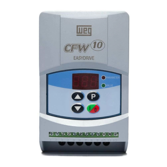
- Page 1 Frequency Inverter Convertidores de Frecuencia Inversores de Freqüência...
- Page 2 FREQUENCY INVERTER MANUAL Series: CFW-10 Software: version 1.0X 0899.5034 E/2 Please take this page out when unpacking the product...
- Page 3 FREQUENCY INVERTER MANUAL Series: CFW-10 Software: version 1.0X 0899.5034 E/2 03/2005 ATTENTION! It is very important to check if the inverter software version is the same as indicated above.
- Page 4 Sumarry of Revisions The table below describes all revisions made to this manual. Revision Description Section First Edition Addition of the CFW10 MECII and addition of the EMC filter for MECI. General revision.
-
Page 5: Table Of Contents
CONTENTS Quick Parameter Reference, Fault and Status Messages I Parameters ..............08 II Fault Messages ............11 III Other Messages ............11 CHAPTER 1 Safety Notices 1.1 Safety Notices in the Manual ........12 1.2 Safety Notice on The Product ........12 1.3 Preliminary Recommendations .........12 CHAPTER 2 General Information... - Page 6 6.3.3 Configuration Parameters - P200 to P398 ..65 CHAPTER 7 Diagnostics and Troubleshooting 7.1 Faults and Possible Causes ........78 7.2 Troubleshooting ............80 7.3 Contacting WEG ............81 7.4 Preventive Maintenance ...........81 7.4.1 Cleaning Instructions .......... 82 CHAPTER 8 Options and Accessories 8.1 RFI Filters ...............
- Page 7 CONTENTS 8.3 Load Reactor ............86 8.4 Rheostatic Braking ...........86 8.4.1 Sizing ..............87 8.4.2 Installation ............88 CHAPTER 9 Technical Specifications 9.1 Power Data ..............89 9.1.1 200-240V Power Supply ........89 9.1.2 110-127 V Power Supply ........89 9.2 Eletronic/General Data ..........91 CHAPTER 10 Warranty Warranty Terms for Frequency Inverters - CFW-10 ..92...
-
Page 8: I Parameters
CFW-10 - QUICK PARAMETER REFERENCE QUICK PARAMETER REFERENCE, FAULT AND STATUS MESSAGES Software: V1.0X Application: Model: Serial Number: Responsible: Date: I. Parameters Factory Parameter Function Adjustable Range Unit User Setting Page Setting 0 to 4, 6 to 999 = Read P000 Parameter Access 5 = Alteration... - Page 9 CFW-10 - QUICK PARAMETER REFERENCE Factory Parameter Function Adjustable Range Unit User Setting Page Setting V/F Control Manual Torque Boost P136 0.0 to 100 20.0 (IxR Compensation ) Automatic Torque Boost P137 0.0 to 100 (automatic IxR Compensation) P138 Slip Compensation 0.0 to 10.0 P142 (1) (2)
- Page 10 CFW-10 - QUICK PARAMETER REFERENCE Factory Parameter Function Adjustable Range Unit User Setting Page Setting Digital Inputs P263 Digital Input DI1 0 = No Function Function 1 = No Function or P264 Digital Input DI2 General Enable Function 2 = General Enable P265 Digital Input DI3 3 = JOG...
-
Page 11: Fault Messages
CFW-10 - QUICK PARAMETER REFERENCE II. Fault Messages Display Description Page Output Overcurrent/Short-Circuit DC Link Overvoltage DC Link Undervoltage Inverter Overtemperature Output Overload (Ixt Function) External Fault CPU Error (Watchdog) Program Memory Error (Checksum) Programming Error Keypad (HMI) Communication Fault Self-Diagnosis Error III. -
Page 12: Safety Notices
CHAPTER 1 SAFETY NOTICES This manual contains necessary information for the correct use of the CFW-10 Variable Frequency Drive. This manual has been written for qualified personnel with suitable training and technical qualification to operate this type of equipment. The following Safety Notices will be used in this manual: SAFETY NOTICES IN THE MANUAL DANGER! - Page 13 CHAPTER 1 - SAFETY NOTICES NOTE! In this manual, qualified personnel are defined as people that are trained to: 1. Install, ground, power up and operate the CFW-10 according to this manual and the local required safety procedures; 2. Use of safety equipment according to the local regulations; 3.
-
Page 14: General Information
As the CFW-10 can be applied in several ways, it is impossible to describe here all of the application possibilities. WEG does not accept any responsibility when the CFW-10 is not used according to this Manual. -
Page 15: About The Cfw-10
CHAPTER 2 - GENERAL INFORMATION 2.3 ABOUT THE CFW-10 The CFW-10 frequency inverter is fitted with the V/F (scalar) control method. The V/F (scalar) mode is recommended for more simple applications such as pump and fan drives. In these cases one can reduce the motor and inverter losses by using the "Quadratic V/F"... - Page 16 CHAPTER 2 - GENERAL INFORMATION Breaking Resistor (Optional) Pre-Load Power L/L1 Supply Motor N/L2 RFI Filter POWER CONTROL POWER SUPPLY FOR ELETRONICS AND INTERFACE BETWEEN POWER AND CONTROL. Digital Inputs "CC10" (DI1 to DI4) CONTROL BOARD WITH DSP Relay Analog Output Input (RL1)
- Page 17 CHAPTER 2 - GENERAL INFORMATION Power L/L1 N/L2 Suplly Motor RFI Filter POWER CONTROL POWER SUPPLY FOR ELETRONICS AND INTERFACE BETWEEN POWER AND CONTROL. Digital "CC10" Inputs CONTROL (DI1 a DI4) BOARD WITH DSP Analog Relay Input Output (AI1) (RL1) Figure 2.3 - CFW-10 Block Diagram for model 1,6A to 2,6 A/110-127 V...
- Page 18 CHAPTER 2 - GENERAL INFORMATION Breaking Resistor (Optional) Power L/L1 N/L2 Suplly Motor Pre-Load RFI Filter POWER CONTROL POWER SUPPLY FOR ELETRONICS AND INTERFACE BETWEEN POWER AND CONTROL. Digital Inputs "CC10" (DI1 a DI4) CONTROL BOARD WITH DSP Analog Relay Input Output (AI1)
-
Page 19: Cfw-10 Identification
CHAPTER 2 - GENERAL INFORMATION CFW-10 IDENTIFICATION Software Version Hardware Revision CFW-10 Model Rated Input Data Rated Output Data (Voltage, Current, etc) (Voltage, Frequency) Serial Number WEG Part Number Manufacturing Date Lateral Nameplate CFW-10 Figure 2.5 - Description and Location of the Nameplate... -
Page 20: Receiving And Storing
CHAPTER 2 - GENERAL INFORMATION HOW TO SPECIFY THE CFW-10 MODEL CFW-10 0040 2024 Rated Output Number of Power Options: Control Special Special End code Manual Series 10 Current for phases of supply: S= standard Board: Hardware Software Language: 00= none 00= none Frequency the power... -
Page 21: Installation And Connection
CHAPTER 3 INSTALLATION AND CONNECTION MECHANICAL This chapter describes the procedures for the electrical and INSTALLATION mechanical installation of the CFW-10. These guidelines and suggestions must be followed for proper operation of the CFW-10. The location of the inverter installation is an important factor 3.1.1 Environment to assure good performance and high product reliability. -
Page 22: Mounting Specifications
CHAPTER 3 - INSTALLATION AND CONNECTION 3.1.2 Mounting Specification Figure 3.1 - Free-Spaces for Cooling CFW-10 Model 1,6A / 200-240V 2,6A / 200-240V 4,0A / 200-240V 7,3A / 200-240V 30 mm 1,18 in 50 mm 2 in 50 mm 2 in 1,6A / 110-127V 2,6A / 110-127V 4,0A / 110-127V... - Page 23 CHAPTER 3 - INSTALLATION AND CONNECTION MEC 1 VIEW OF THE FRONTAL LATERAL VIEW MOUNTING BASE VIEW MEC 2 Figure 3.2 - Dimensional Drawings of the CFW-10 - MEC 1 and 2...
-
Page 24: Electrical Installation
CHAPTER 3 - INSTALLATION AND CONNECTION Dimensions Fixing Base Height Depth Width Mounting Weight Degree of Model Screw Protection (in) (in) (in) (in) (lb) (in) (in) (in) 119.8 1,6A / 200-240V IP20 (4.76) (3.74) (5.20) (3.35) (4.72) (0.2) (0.24) (1.98) 119.8 2,6A / 200-240V IP20... - Page 25 CHAPTER 3 - INSTALLATION AND CONNECTION DANGER! Be sure the AC input power has been disconnected before making any terminal connection. DANGER! The information below will be a guide to achieve a proper installation.Follow also all applicable local standards for electrical installations.
- Page 26 CHAPTER 3 - INSTALLATION AND CONNECTION L/L1 N/L2 Braking Resistor L/L1 N/L2 Shielding Power Supply b) Models 7,3A/200-240V and 4,0A/110-127V Figure 3.4 a) and b) - Grounding and power supply conections DANGER! The inverter must be grounded to a protective earth for safety purposes (PE).
- Page 27 CHAPTER 3 - INSTALLATION AND CONNECTION NOTE! Do not use the neutral conductor for grounding purposes. ATTENTION! The AC input for the inverter supply must have a grounded neutral conductor. NOTE! The AC input voltage must be compatible with the inverter rated voltage.
- Page 28 CHAPTER 3 - INSTALLATION AND CONNECTION Use wire sizing and circuit breakers as recommended in Table 3.3. Tightening torque is as indicated in Table 3.4. Use (70ºC) copper wires only. Rated Motor Grounding Power Maximum Circuit-Breaker Inverter Wiring Wiring Cables Cables Current Current...
-
Page 29: Power Terminals
CHAPTER 3 - INSTALLATION AND CONNECTION 3.2.2 Power Terminals Description of the Power Terminals: L/L1, N/L2 : AC supply line U, V and W: Motor connection. PE: grounding connection. BR: Connection terminal for the braking resistor. Not available for 1,6A, 2,6A and 4A/200-240V and 1,6A and 2,6A/110-127V models. -
Page 30: Location Of The Power/Grounding/Control Connections
CHAPTER 3 - INSTALLATION AND CONNECTION 3.2.3 Location of the Power, Grounding and Control Connections Control XC1 Power Figure 3.7 - Location of the Power and Control Connections 3.2.4 Signal and Control The signal (analog input) and control connections (digital inputs Connections and relay output) are made on the XC1 connector of control board (see location in Figure 3.7). - Page 31 CHAPTER 3 - INSTALLATION AND CONNECTION NOTE! If the input current from 4 mA to 20 mA is used as standard, do not forget to set the Parameter P235 which defines the signal type at AI1. During the signal and control wire installation note the following: 1) Cable cross section: (0.5 to 1.5) mm²...
-
Page 32: Typical Terminal Connections
CHAPTER 3 - INSTALLATION AND CONNECTION 6) When analog reference (AI1) is used and the frequency oscillates (problem caused by electromagnetic interference) connect XC1:7 to the inverter grounding bar. 3.2.5 Typical Terminal Connection 1 Connections With the factory default programming, it is posible to operate the inverter in local mode with the minimum connections shown in Figure 3.4 (Power) and without control connections. - Page 33 CHAPTER 3 - INSTALLATION AND CONNECTION When a line fault occurs by using this type of connection with switch S3 at position "RUN", the motor will be enabled automatically as soon as the line is re-established. Connection 3 Start / Stop function enabling (three-wire control): Set DI1 to Start: P263=13 Set DI2 to Stop: P264=14 Set P229=1 (commands via terminals) if you want the 3-wire...
-
Page 34: European Emc Directive
CHAPTER 3 - INSTALLATION AND CONNECTION motor running and the S1 and S2 switches are in original position (S1 openned and S2 closed), the inverter will not be enabled automatically as soon as the line is re- restablished. The Start/Stop function is described in Chapter 6. Connection 4 Enabling of the FWD / REV function: Set DI1 to Forward Run : P263 = 9... -
Page 35: Installation
CHAPTER 3 - INSTALLATION AND CONNECTION EMC Directive. The end user takes personal responsibility for the EMC compliance of the whole installation. However, when installed according to the recommendations described in the product manual and including the recommended filters and EMC measures the CFW-10 fulfill all requirements of the EMC Directive (89/336/EEC) as defined by the EN61800-3 "EMC Product Standard for Adjustable Speed Electrical Power Drive Systems - specific standard for variable speed... -
Page 36: Emc Categories Description
CHAPTER 3 - INSTALLATION AND CONNECTION 5) The cable shield (motor and control) shall be solidly connected to the common back plate, using metallic brackets. 6) Grounding shall be performed as recommended in this user’s guide. 7) Use short and thick cables to ground the external filter or inverter. - Page 37 CHAPTER 3 - INSTALLATION AND CONNECTION Category II Basic standard EMC phenomenon Level for test method Emission: Conducted emissions (mains terminal Class B IEC/EN61800-3 disturbance voltage - freq band 150kHz to 30MHz) Radiated emissions (electromagnetic First environment (*1), restricted distribution (*4,5) IEC/EN61800-3 radiation disturbance - freq band 30MHz to 1000MHz)
-
Page 38: Inverter And Filters
CHAPTER 3 - INSTALLATION AND CONNECTION + A11 (2000). In a domestic environment this product may cause radio interference in which case the user may be required to take adequate measures. 6) The harmonic current emissions defined by the standards IEC/EN61000-3-2 and EN61000-3-2 / A14 do not apply because the CFW-10 inverter series are intended for professional applications. -
Page 39: Characteristics Of The Emc Filters
CHAPTER 3 - INSTALLATION AND CONNECTION 3.3.4 Characteristics of the EMC Filters Footprint / booksize Model B84142A0012R212 (EPCOS) Supply voltage: 250V, 50/60Hz Current: 12A Weight: 0,95Kg Terminals 2,5 mm Tightgning torque of screw max. 0,5 Nm 3 x litzwire 2,5 mm 3 x wire and sleeve DIN 46228-A2, 5-10 Figure 3.14 –... - Page 40 CHAPTER 3 - INSTALLATION AND CONNECTION Standard Model: B84142 - A20-R Supply voltage: 250V, 50/60Hz Current: 20A Weight: 1 kg Terminais Terminais Figure 3.15 – Drawing of the Standard Filter: B84142-A20-R (EPCOS)
-
Page 41: Start-Up
CHAPTER 4 START-UP This Chapter provides the following information: how to check and prepare the inverter before power-up; how to power-up and check for proper operation; how to operate the inverter when it is installed according to the typical connections (refer to Section 3.2 - Electrical Installation). -
Page 42: Start-Up
CHAPTER 4 - START-UP START-UP DANGER! Even after the AC power supply has been disconnected, high voltages may be still present. Wait at least 10 minutes after powering down to allow full discharge of the capacitors. The sequence below is valid for the connection 1 (refer to 4.3.1 Start-up Section 3.2.5). -
Page 43: Start-Up Operation Via Terminals
CHAPTER 4 - START-UP The sequence below is valid for the connection 1 (refer to 4.3.2 Start-up Section 3.2.5). Inverter must be already installed and powered Operation Via Terminals up according to Chapter 3 and Section 4.2. Connections according to Figures 3.4 and 3.10. ACTION HMI DISPLAY DESCRIPTION... -
Page 44: Keypad (Hmi) Operation
CHAPTER 5 KEYPAD (HMI) OPERATION This chapter describes the CFW-10 operation via Human- Machine Interface (HMI), providing the following information: general keypad description (HM)I; use of the keypad (HMI); parameter programming; description of the status indicators. The standard CFW-10 keypad has a LED display with 3 digits KEYPAD (HMI) of 7 segments, 2 status LEDs and 4 keys. -
Page 45: Use Of The Keypad Hmi
CHAPTER 5 - KEYPAD (HMI) OPERATION Increases the frequency, the parameter number or the parameter value. Decreases the frequency, the parameter number or the parameter value. The Keypad (HMI) is a simple interface that allows inverter USE OF THE KEYPAD operation/programming. -
Page 46: Inverter Status
CHAPTER 5 - KEYPAD (HMI) OPERATION Parameter P121 stores the speed reference set by these keys. When pressed, it increases the speed (frequency) reference. When pressed, it decreases the speed (frequency) reference. Reference Backup The last frequency reference, set by the keys the ,is stored when inverter is stopped or the AC power is removed, provided P120 = 1 (reference backup active is the factory default). -
Page 47: Parameter Viewing And Programming
CHAPTER 5 - KEYPAD (HMI) OPERATION 5.2.4 Parameter Viewing and Parameters and their contents are shown on the Display Programming through the LED´s " Parameter" and "Value". The identification is made between parameter number and its value. Example (P101): Parameter Parameter Value Value... - Page 48 CHAPTER 5 - KEYPAD (HMI) OPERATION NOTE! (1)For parameters that can be changed with the running mo- tor , the inverter will use the new value immediately after it has been set. For parameters that can be changed only with stopped motor , the inverter will use this new value only after the key is pressed.
-
Page 49: Detailed Parameter Description
CHAPTER 6 DETAILED PARAMETER DESCRIPTION This chapter describes in detail all CFW-10 parameters and functions. 6.1 SYMBOLS Please find below some symbols used in this chapter: AIx = Analog input number x. AO = Analog output. DIx = Digital input number x. F* = Frequency reference. -
Page 50: Frequency Reference Sources
CHAPTER 6 - DETAILED PARAMETER DESCRIPTION There is still a variation of the linear V/F control: the quadratic V/F control. This control mode is suitable for applications like centrifugal pumps and fans (loads with quadratic torque x speed characteristics), since it enables a motor loss reduction, resulting in an additional energy saving by using an inverter. - Page 51 CHAPTER 6 - DETAILED PARAMETER DESCRIPTION Frequency Reference Selection P221 or P222 Keypad Reference (P121) 0 - Keypad P263=7/8 P124 to P131 P264=7/8 P265=7/8 P266=7/8 P131 P130 P129 P128 P127 P126 P125 6 - Multispeed P124 000 001 010 011 100 101 110 111 MULTISPEED 4 to 20mA Reset...
- Page 52 CHAPTER 6 - DETAILED PARAMETER DESCRIPTION P151 DC Link Power Regulation Supply P151 P100 P101 P136, P137, P138, P142, P133 P134 P202 P295 P145 Acceleration & Deceleration Inverter Ramp Control (V/F or P102 P103 Vector) Frequency Reference Motor Parameters Limits P178 (P399 to P409) Acceleration&...
-
Page 53: Commands
CHAPTER 6 - DETAILED PARAMETER DESCRIPTION 6.2.3 Commands The inverter has the following commands: PWM pulse enabling/disabling, definition of the direction of rotation and JOG. As the frequency reference, also the inverter commands can de defined in several ways. The mais command sources are: via keypad key -key via control terminals (XC1) - digital inputs;... -
Page 54: Parameter Listing
CHAPTER 6 - DETAILED PARAMETER DESCRIPTION Local/Remote Selection LOCAL DI1 to DI4 (P263 to P266) 0 Keypad - HMI 1 AI1 Frequency 2 EP Reference 3 to 5 Reserved REFERENCE P221 6 Multispeed Controls 0 Keypad - HMI P229 COMMANDS 1 TerminalsXC1 (DIs) (run/stop) -
Page 55: Access And Read Only Parameters - P000 To P099
CHAPTER 6 - DETAILED PARAMETER DESCRIPTION 6.3.1 Access and Read Only Parameters - P000 to P099 Range [Factory Setting] Parameter Description / Notes Releases the access to change the parameter values. P000 0 to 999 The password is 5. Access [ 0 ] The use of the password is always active. -
Page 56: Regulation Parameters - P100 To P199
CHAPTER 6 - DETAILED PARAMETER DESCRIPTION 6.3.2 Regulation Parameters - P100 to P199 Range [Factory Setting] Parameter Description / Notes 0.1 to 999s This set of parameters defines the time to accelerate P100 [ 5.0s ] linearly from zero up to the rated frequency and to Acceleration 0.1s (<100);... - Page 57 CHAPTER 6 - DETAILED PARAMETER DESCRIPTION Range [Factory Setting] Parameter Description / Notes P120 0 to 2 Defines if the inverter should save or not the last used Digital Reference [ 1 - active] digital reference. This backup function is only applicable Backup to the keypad reference (P12).
- Page 58 CHAPTER 6 - DETAILED PARAMETER DESCRIPTION Range [Factory Setting] Parameter Description/Notes P124 P133 to P134 Multispeed is used when the selection of up to 8 pre- Multispeed Ref. 1 [ 3.0Hz ] programmed speeds are required. 0.1Hz (<100Hz); It allows the control of the output speed related to the 1Hz (>99.9Hz) values programmed by the parameters P124 to P131, according to the logical combination of the digital inputs...
- Page 59 CHAPTER 6 - DETAILED PARAMETER DESCRIPTION Range [Factory Setting] Parameter Description / Notes P131 Output Frequency P130 P129 P128 Acceleration P127 Ramp P126 P125 P124 Time open open open Figure 6.5 - Time Diagram of the mulltispeed function P133 0.0 to P134 Defines the maximum and minimum output frequency Minimum [ 3.0Hz ]...
- Page 60 CHAPTER 6 - DETAILED PARAMETER DESCRIPTION Range [Factory Setting] Parameter Description / Notes Output Voltage (% of the line voltage) P142 0,3xP136xP142 Output frequency P145 (a) P202=0 Output Voltage (% of the line voltage) P142 P136 Output frequency P145 (b) P202=1 Figure 6.6 - V/F curve and details of the manual torque boost (IxR compensation) P137...
- Page 61 CHAPTER 6 - DETAILED PARAMETER DESCRIPTION Range [Factory Setting] Parameter Description / Notes P007 Motor Speed voltage P136 Reference (F*) Active Output Automatic Current (I P137 Filter Figure 6.7 - Block diagram of the automatic torque boost function Output Voltage Maximum (P142) 0,3xP137xP142...
- Page 62 CHAPTER 6 - DETAILED PARAMETER DESCRIPTION Range [Factory Setting] Parameter Description / Notes Output Voltage (function of the motor load) Output frequency Figure 6.10 - V/F curve with slip compensation To set the parameter P138 adopt the following procedure: - run the motor without load up to approximately half of the application top speed;...
- Page 63 CHAPTER 6 - DETAILED PARAMETER DESCRIPTION Range [Factory Setting] Parameter Description / Notes Ouput Voltage P142 Output Frequency 0.1Hz P145 Figure 6.11 - Adjustable V/F curve P151 360 to 460V The DC link voltage regulation (ramp holding) avoids in- DC Link Volage (line 110-127V) verter disable due to overvoltage trips (E01) during Regulation Level...
- Page 64 CHAPTER 6 - DETAILED PARAMETER DESCRIPTION Range [Factory Setting] Parameter Description / Notes The motor will not stop if the line is permanently with overvoltage (U >P151). In this case, reduce the line voltage, or increase the value of P151. If even with these settings the motor does not decelerate within the required time, you will have the alternative to increase P136;...
-
Page 65: Configuration Parameters - P200 To P398
CHAPTER 6 - DETAILED PARAMETER DESCRIPTION 6.3.3 Configuration Parameters - P200 to P398 Range [Factory Setting] Parameter Description / Notes Defines the inverter control mode. P202 0 to 1 Type of Control [ 0 - V/F linear ] Type of Control P202 Linear V/F Control (scalar) Quadratic V/F Control (scalar) - Page 66 CHAPTER 6 - DETAILED PARAMETER DESCRIPTION Range [Factory Setting] Parameter Description / Notes Output Voltage P136=0 P142 Output Frequency P145 (b) Quandratic V/F Figure 6.15 - V/F Control MODES (scalar) Programs all parameters to the standard factory default, P204 0 to 999 when P204=5.
- Page 67 CHAPTER 6 - DETAILED PARAMETER DESCRIPTION Range [Factory Setting] Parameter Description / Notes P221 0 to 6 Defines the frequency reference selection in the Local and Local Reference [ 0 - keys ] Remote mode. Selection P221/P222 Reference Source P222 0 to 6 Keys of the HMIs (P121)
- Page 68 CHAPTER 6 - DETAILED PARAMETER DESCRIPTION Range [Factory Setting] Parameter Description / Notes P234 0.0 to 999 The analog input AI1 defines the inverter frequency Analog Input AI1 [ 100 ] reference as shown in the curve below. Gain 0.1% Frequency Reference P134 P133...
- Page 69 CHAPTER 6 - DETAILED PARAMETER DESCRIPTION Range [Factory Setting] Parameter Description / Notes Following situation as example:AI1 is the voltage input (0-10V - P235=0), AI1=5V, P234=1.00 and P236=-70%. Thus (-70) . AI1' = 1 = -0.2 = -20% 10 100 The motor will run in reverse direction of rotation as defined by the commands (negative value) - if this is possible (P231=2), with a module reference equal to 0.2...
- Page 70 CHAPTER 6 - DETAILED PARAMETER DESCRIPTION Range [Factory Setting] Parameter Description / Notes P266 0 to 21 DI Parameter DI1 (P263), DI2 (P264), Function DI3 (P265), DI4 (P266) Digital Input DI4 [ 4 - Not used (HMI) Not used Function- or Start/Stop Not used (HMI) or (Terminals) ]...
- Page 71 CHAPTER 6 - DETAILED PARAMETER DESCRIPTION Range [Factory Setting] Parameter Description / Notes 6) If different acceleration and deceleration times are desired for a given operation condition (for instance for a set of frequencies or for a direction of rotation), check if it possible to use the multispeed function with ramp #2 and FWD/REV with ramp #2.
- Page 72 CHAPTER 6 - DETAILED PARAMETER DESCRIPTION d) FORWARD RUN / REVERSE RUN DI1 - FWD open Time open DI2 - REV Time Output frequency (Motor speed) Time e) ELECTRONIC POTENTIOMETER (EP) Minimum Frequency (P133) Output frequency (Motor Time speed) DI3 - Increase PE open Time...
- Page 73 CHAPTER 6 - DETAILED PARAMETER DESCRIPTION h) JOG JOG Frequency (P122) Output frequency Accel. (Motor Ramp Decel. speed) Ramp Time Start/Stop open Time DI - JOG open Time General open Enable Time i) NO EXTERNAL FAULT motor runs freely Output frequency (Motor speed) Time DI - No external fault...
- Page 74 CHAPTER 6 - DETAILED PARAMETER DESCRIPTION Range [Factory Setting] Parameter Description / Notes Table below shows the possible options. P277 0 to 7 Relay Output RL1 [ 7 - No fault ] P277 Output/Parameter Function Function (RL1) Fs > Fx Fe >...
- Page 75 CHAPTER 6 - DETAILED PARAMETER DESCRIPTION Range [Factory Setting] Parameter Unit Description / Notes When the definition in the function name is true, the digi- tal output will be activated, i.e., the relay coil is energized. When the option 'Not used' has been programmed, the relay output(s) will be disabled, i.e., the coil is not energized.
- Page 76 CHAPTER 6 - DETAILED PARAMETER DESCRIPTION Range [Factory Setting] Parameter Unit Description / Notes 10.1 kHz to 5.1 kHz to Inverter Model 2.5 kHz to / P297 5.0 kHz 15.0 kHz 10.0 kHz 1.6A 1.6A CFW100016S ... 1.6A 2.1A 2.6A CFW100026S ...
- Page 77 In applications where the motor current is lower than the rated inverter current, and where the braking torque is not enough for the braking condition, please contact WEG to optimize the settings.
-
Page 78: Diagnostics And Troubleshooting
CHAPTER 7 DIAGNOSTICS AND TROUBLESHOOTING This chapter assists the user to identify and correct possible faults that can occur during the CFW-10 operation. Also instructions about required periodical inspections and cleaning procedures are also provided. FAULTS AND POSSIBLE CAUSES When a fault is detected, the inverter is disabled and the fault code is displayed on the readout in EXX form, where XX is the actual fault code. - Page 79 Keypad (HMI) Servicing Electrical noise in the installation (electromagnetic Connection Fault (Refer to Item 7.3) interference). Contact WEG Servicing Inverter power circuit is defective. Self- Diagnosis (refer to section 7.3) Fault Note: In case of E04 Fault due to inverter overtemperature, allow the inverter to cool down before trying to reset it.
-
Page 80: Troubleshooting
DIAGNOSTICS AND TROUBLESHOOTING CHAPTER 7 - TROUBLESHOOTING POINT TO BE PROBLEM CORRECTIVE ACTION CHECKED Motor does not run Incorrect wiring 1.Check the power and the control connections. For example, the digital inputs DIx programmed for Start/Stop or General Enable or No External Fault must be connected to GND (pin 5 of the control connector XC1). -
Page 81: Contacting Weg
DIAGNOSTICS AND TROUBLESHOOTING CHAPTER 7 - CONTACTING WEG NOTE! When contacting WEG for services, please have the following data on hand: Inverter model; Serial number, manufacturing date and hardware revision, as indicated on the inverter nameplate (refer to section 2.4);... -
Page 82: Cleaning Instructions
DIAGNOSTICS AND TROUBLESHOOTING CHAPTER 7 - COMPONENTS PROBLEMS CORRECTIVE ACTIONS Terminal blocks Loose screws Tighten them Loose connectors Printed circuit boards Dust, oil or moisture accumulation Clean them and/or replace them Smell Replace them Table 7.1 - Periodic inspection after start-up ATTENTION! If the inverter is stored for long periods, we recommend to power it up once a year during 1 hour. -
Page 83: Rfi Filters
CHAPTER 8 CFW-10 OPTIONS AND ACCESSORIES This Chapter describes the optional devices that can be used internal or external with the CFW-10. RFI FILTER The installation of frequency inverters requires some care in order to prevent electromagnetic interferences (EMI). This electromagnetic interference may disturb the operation of the inverter itself or other devices, such as electronic sensors, PLCs, transducers, radio equipment, etc. -
Page 84: Options And Accessories
CHAPTER 8 - OPTIONS AND ACCESSORIES Driving Panel CFW-10 Conduit or Shielded Cable Motor Filter Power Supply Motor Ground Ground (frame) Figure 8.21 - Connection of the external RFI filter LINE REACTOR Due to the input circuit characteristic, common to the most inverters available on the market, consisting of a diode rectifier and a capacitor bank, the input current (drained from the power supply line) of inverters is a non sinusoidal waveform and... - Page 85 CHAPTER 8 - OPTIONS AND ACCESSORIES Always add a line reactor, when capacitors for power factor correction are installed in the same line and near to the inverter. Figure 8.2 shows the line reactor connection to the input. Use the following equation to calculate the value of the line reactor necessary to obtain the desired percentage of the voltage drop: L = 1592 .
-
Page 86: Load Reactor
(as a function of the "transmission line" effect) are used. WEG Motor with voltages up to 460V, no use of load reactor is required, since the insulation of the motor wires support the operation bi the CFW-10. If the cables between inverter and motor are longer than 100m (300ft), the cable capacitance to ground increases. -
Page 87: Sizing
CHAPTER 8 - OPTIONS AND ACCESSORIES In any case, the RMS current capacity and the maximum peak current shall be respected. The maximum peak current defines the minimum resistance value (ohms) of the braking resistor. Refer to table 8.3. The DC Link voltage level at which the rheostatic braking is activated is the following: - CFW-10 200-240V models –... -
Page 88: Installation
CHAPTER 8 - OPTIONS AND ACCESSORIES 8.4.2 Installation Connect the braking resistor between the +UD and BR power terminals (Refer to Section 3.2.1); Make this connection with a twisted pair. Run this cable separately from any signal or control wire. Size the cable cross section according to the application, considering the maximum and RMS current;... -
Page 89: Technical Specifications
CHAPTER 9 TECHNICAL SPECIFICATIONS This chapter describes the technical specifications (electrical and mechanical) of the CFW-10 inverter series. 9.1 POWER DATA AC Input Specifications: Voltage: -15%, +10% (with loss of motor efficiency) Frequency : 50/60Hz (± 2 Hz) Overvoltage: Category III (EN 61010/UL 508C) Transient voltages according to Category III. - Page 90 IV-pole motors and normal duty loads. The precise in- verter sizing must consider the actual motor nameplate and application data. (5) WEG inverters are supplied with parameter settings for WEG IV pole standard motors, 60 Hz, 220V and outputs as indicated above.
-
Page 91: Eletronic/General Data
CHAPTER 9 - TECHNICAL SPECIFICATIONS ELECTRONIC/GENERAL DATA METHOD Applied Voltage V/F (scalar) CONTROL OUTPUT 0 to 300Hz, resolution: 0,01Hz. FREQUENCY PERFORMANCE V/F Control Speed regulation: 1% of the rated speed. INPUTS ANALOG 1 isolated input, resolution: 7 bits, (0 to 10)V or (0 to 20)mA, or (CC10 Board) (4 to 20)mA Impedance: 100kΩ... - Page 92 The warranty period is for twelve months from the invoice date of the equipment issued by WEG or its authorized distributor, proved through equipment invoice, but limited to twenty four months from the manufacturing date, that is indicated on the product nameplate.
- Page 93 12.0 Any request, complaint, communication, etc. related to the product under warranty, servicing, start-up, etc., shall be sent in writing to WEG Branch or Representative. 13.0 The Warranty granted by WEG is conditioned by the observation of this warranty that is the only valid warranty for the good.
Need help?
Do you have a question about the CFW-10 EASYDRIVE and is the answer not in the manual?
Questions and answers