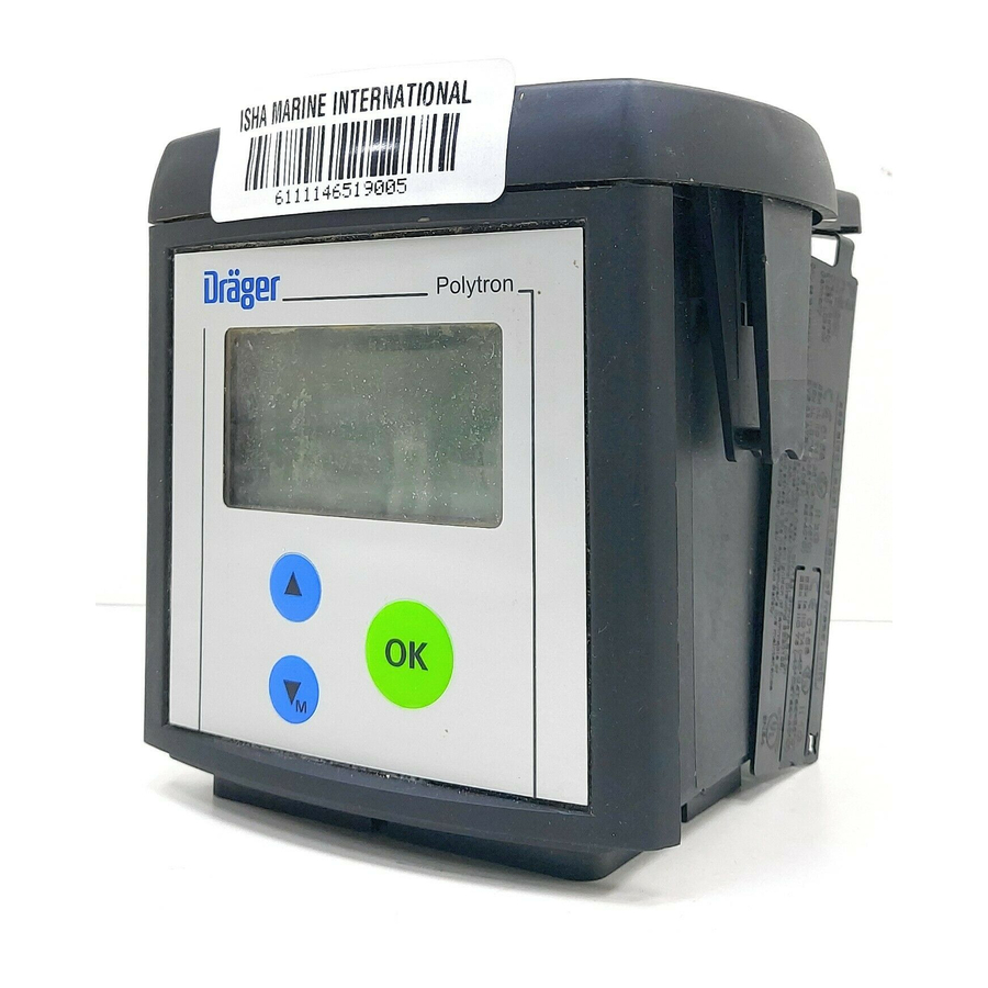
Dräger Polytron 7000 Instructions For Use Manual
Approved as type p3u and p3fb. transmitter for electrochemical sensors
Hide thumbs
Also See for Polytron 7000:
- Instructions for use manual (140 pages) ,
- Manual (12 pages) ,
- Installation instructions manual (8 pages)

Related Manuals for Dräger Polytron 7000


Summary of Contents for Dräger Polytron 7000
- Page 1 Dräger Polytron 7000 (approved as type P3U and P3FB) Transmitter for electrochemical Sensors Instructions for Use...
-
Page 2: Table Of Contents
Duct adapter for remote sensor ........29 Dräger Polytron 7000 software dongles ......30 Relay module . - Page 3 Submenu » Datalogger « ........79 Polytron 7000 Operation via LON ......82 Polytron 7000 Operation via PROFIBUS PA .
-
Page 4: For Your Safety
If the transmitter is equipped, either when delivered or subsequently, with the relay module and/or the pump module, the complete unit is no longer approved for use in explosion-hazard areas. The use of the Dräger Polytron 7000 equipped with a pump module and/or relay module in explosion-hazard areas is forbidden! Explosion hazard! Not suitable for use in oxygen-enriched atmospheres, i.e. -
Page 5: Intended Use
Intended Use Intended Use ® Dräger Polytron 7000 Transmitter for electrochemical sensors ® — For stationary, continuous monitoring of gas concentrations in ambient air, with built-in DrägerSensor — Automatic configuration of transmitter to suit the built-in DrägerSensor. — The measuring range may be selected, but it is dependent on the sensor installed. —... - Page 6 — Special calibration mode (blocking of alarm triggering, display of calibration mode, one-man calibration). Detection of oxygen in accordance with EN 50104 CAUTION If the Dräger Polytron 7000 transmitter is used for the detection of oxygen, at least one alarm relay must be config- ured as latching. Measuring function for the explosion protection BVS 03 ATEX E 406 X Dräger Polytron 7000 4 to 20 mA...
-
Page 7: Design
This option is only possible without explosion protection approval. Explosion hazard! If the Dräger Polytron 7000 transmitter is used in connection with the relay module for detecting oxygen according to EN 50104, the transmitter has to be equipped with software version 8.0 or higher. - Page 8 Design Daisy-chain kit For the connection of several Dräger Polytron 7000 transmitters to one bus line (multidrop installation). This option does not affect the explosion-protec- tion approval of the transmitter. Duct extension For mounting the Polytron 7000 transmitters on a duct.
-
Page 9: Installing The Transmitter
NOTE In explosion-hazard areas: Observe the national regulations concerning electrical equipment in explo- sion-hazard areas. The Dräger Polytron 7000 transmitter consists of several components: — Dräger docking station This can be pre-installed anywhere and contains the electrical installation components. — The measuring unit Dräger Polytron 7000 contains the electronics of the transmitter. -
Page 10: Installing The Docking Station
Installing the transmitter Installing the docking station — If the transmitter is to be installed in a Zone 2 explosion-hazard area, select a location with low exposure to mechanical risk. — Docking station is installed vertically (transmitter with sensor facing down) in an area with low vibrations and stable temperatures –... -
Page 11: Electrical Connections
Connect shield to earth of central unit (e.g. housing, earth bar, etc.). Connecting the Dräger Polytron 7000 transmitter to a Dräger control unit (such as Regard, QuadGard, Unigard or Polytron): — Further information about the connection can be found in the instructions for the Dräger control unit. - Page 12 Electrical connections Installing transmitter in mines where firedamp may occur — Install a safety barrier with the appropriate explosion protection approval (device category M1) between the transmitter and the control unit. — Only safety barriers or power supply units with the following characteristics may be used: U ) = 30 V, I ) = 0.3 A, P...
- Page 13 Electrical connections Ω — The cable resistances given apply for a load resistance of 250 . Higher load resistances can drastically reduce the permissible cable resistance! When other barriers have been selected, care must be taken that the volt- ages on the transmitter do not fall below the following values when barrier parameters and cable resistance are taken into account: 16.5 V for a current of 3 mA and 8.0 V for a current of 22 mA.
- Page 14 1 Use a 4-pole terminal block (X7), Part No. 83 16 268, for the Dräger Polytron 7000 – Observe the polarity of the connections. Cut excess wires short or 2 secure them in center terminals (Part No. 83 16 422).
- Page 15 Electrical connections Installing the transmitter in areas subject to explosion hazards of Zone 0 or Zone 1: Only safety barriers with the following characteristics may be used: ≤24 V, I ≤0.38 A, P ≤5.32 W or those which correspond to the FISCO model ia or ib.
-
Page 16: 3-Wire Connection
20 V. This must be taken into account when de- termining the maximum cable length (see the table on page 21). — Unigard is not suitable for the connection of a Polytron 7000 transmitter equipped with a relay or pump module. - Page 17 Electrical connections — Ensure that the supply voltage provided by the control unit (ignoring the load resistance) is at least as high as specified in the tables of page 21 to page 22. — If digital communication in accordance with HART is to be used, the load Ω.
-
Page 18: Connections Between Several Transmitters And A Control Unit With Hart Multidrop Connections
Electrical connections Connections between several transmitters and a control unit with HART multidrop connections Each transmitter must first be put into service separately. Use the menu item "Polling Address" to assign a different polling address in the range "1" to "15"... - Page 19 Electrical connections — The cable resistances given apply for the maximum possible number of Ω transmitters as well as a load resistance of 250 . Higher load resistances can drastically reduce the maximum possible cable resistance! The following tables show permissible combinations of transmitters, supply ...
- Page 20 Electrical connections Installing the transmitters in explosion-hazard areas of zone 2 without a safety barrier — Use only supply units of the device category 3. For safety reasons, we recommend that not more than 8 transmitters be connected to a 2-wire or 3-wire cable. —...
- Page 21 Electrical connections Transmitter without relay or pump module (2-wire): Maximum cable length with a load resistance of 250 Ω Minimum Number of trans- 0.5 mm 0.75 mm 1.5 mm 2.5 mm supply voltage mitters 265 pF/m 320 pF/m 375 pF/m 400 pF/m 1042 m 921 m...
- Page 22 Electrical connections Transmitter with pump module (3-wire): Maximum cable length with a load resistance of not more than 500 Ω Minimum Maximum pos- Number of supply voltage sible transmitters 0.5 mm 0.75 mm 1.5 mm 2.5 mm flow-rate 265 pF/m 320 pF/m 375 pF/m 400 pF/m...
-
Page 23: 4-Wire Connection
2.5 mm (AWG 13). Installing the LON Communication on the transmitter — For installation using LON communication up to 63 Polytron 7000 can be connected to a four wire cable in any configuration including bus, star, loop and mixed. Insert the 4-wire connecting cable in the cable gland, cut it to length and ... - Page 24 Shorten the shield (if installed) to prevent short-circuiting. Connect cable: 1 4-pin terminal block for Dräger Polytron 7000, observing the polarity. 2 4-pin terminal block for Dräger Polytron 7000, observing the polarity. Slide connecting terminal back into holder. ...
-
Page 25: Installing The Measuring Unit Dräger Polytron 7000
Electrical connections Installing the measuring unit Dräger Polytron 7000 Remove the rain cover from the previously installed docking station. Examine seal for signs of dirt and clean if necessary. 1 Check position of eccentric catches and correct if necessary. -
Page 26: Fitting The Sensor
Electrical connections Fitting the sensor 1 Remove bayonet ring from transmitter, remove dummy plate. Remove sensor from packaging. Remove the short-circuit strap from the sensor (if it is fitted). There is a coded connector on the back of the sensor. Place the sensor in Polytron ... -
Page 27: Installing Accessories
Installing accessories Installing accessories Various accessories are available for the Dräger Polytron 7000 transmitter and may also be installed later. Daisy chain kit – Cable Entry Kit Intended use Daisy chain kit – 83 17 282: — For the connection of several transmitters to one bus cable (daisy chain or... -
Page 28: Remote Sensor
— For installation of the sensor at a distance of up to 30 m from the Polytron 7000 transmitter. Remote Cable + Sensor plug 5 m Polytron 7000 – 83 17 270Remote Cable + Sensor adapter, 15 m Polytron 7000 – 83 17 998, Remote Cable + Sensor plug 30 m Polytron 7000 –... -
Page 29: Duct Adapter For Remote Sensor
4 Connect the plug of the Remote Cable (cable length 5, 15 or 30 m) to the remote sensor adapter and secure it by turning the ring clockwise. 5 Insert the sensor plug in the opening on the Dräger Polytron 7000 transmit- ter with the "Dräger" logo pointing to the front. -
Page 30: Dräger Polytron 7000 Software Dongles
Dräger Polytron 7000 software dongles Intended use Dräger Polytron 7000 software dongle – 83 17 618, 83 17 619 or 83 17 860: — For activating additional functions in the Dräger Polytron 7000: Data Dongle — Activates the Event Logger, the Datalogger 83 17 618 and the graphical concentration display. - Page 31 Installing accessories 3 Bend the snap-hooks on the cover of the measuring unit slightly outwards to release them. 4 Remove the cover. Polytron 5 Hold the dongle with the "Dräger" logo pointing towards the measuring unit. Then insert the dongle into any of the three slots. Up to three dongles may be installed simultaneously.
-
Page 32: Relay Module
The user must ensure that no related approval markings are left on the Poly- tron 7000. The explosion-protection markings has to be removed from the transmitter. The use of the Polytron 7000 with a pump module and/or relay module installed is not permitted in explosion-hazard areas! Explosion hazard! NOTE For operation with the relay module, the transmitter must have a 3-wire con- nection to the control unit. - Page 33 Installing accessories 4 Plug the connection cable into the male connector behind the display, en- suring that the cable is not twisted. Place the relay module on the measuring unit and snap it into position on both sides. In order to make this step easier, the relay cover may be removed. CAUTION 5 Take care that pressure is applied only to the sleeve of measuring unit.
-
Page 34: Pump Module
The user must ensure that no related approval markings are left on the Poly- tron 7000. Remove or cut away any existing approval label. The use of the Polytron 7000 with a pump module and/or relay module installed is not permitted in explosion-hazard areas! Explosion hazard! - Page 35 Installing accessories 4 Check, from the bottom side of the docking station, that the holes go all the way through. Check that the docking station has no loose parts, and clean it if necessary. 3 Remove the O-rings from the glass tube and insert them into the grooves on the bottom of the docking station.
- Page 36 Installing accessories 5 Slide the measuring unit with pump module into the docking station and lower it into position, see page 25. 6 Turn the eccentric catches clockwise with an Allen key to lock the measur- ing unit ( = approx.
- Page 37 Installing accessories — The pressure difference between the flow inlet and the environment of the transmitter can cause an additional measurement error. CAUTION In order to check for leaks, we recommend that you measure the flow at the inlet point and behind the transmitter before using the pump module for the first time and every six months thereafter.
-
Page 38: Start-Up
Switch on power supply. The transmitter begins its warm-up routine: Pioneering Solutions Polytron 7000 — The software version, the date and the time are displayed. NOTE SWversion: 8.0 For the correct operation and functionality it is important to set the date and time. - Page 39 — A current between 4 and 20 mA flows through the transmitter during normal operation. This current is proportional to the gas concentration. — The Dräger Polytron 7000 transmitter uses various current values to indi- cate the operational status of the transmitter:...
-
Page 40: Activating Info Mode
Start-up The following icons may be displayed on the right side of the display in measuring mode in order to indicate the operating status of the unit: A warning exists – see page 55 for information on how warnings are dis- played. - Page 41 Start-up Example of info mode: Screen 1 07.11.2011 12:34 Instrument information SW Version : 8.0 Line 1 – Date and time Part No. : 8317778 Serial No. : ARUA0001 Line 2 – Software version DeviceCode: 00006317 Line 3 – Unit Part No. Line 4 –...
- Page 42 Start-up If "xx.xx.xx xx:xx" is displayed instead of the date and time, or if an incorrect date and time are displayed: (only after the cock has been reset due to a power failure) Set the date and time, see page 67. ...
-
Page 43: Maintenance
Maintenance Maintenance Maintenance intervals Before starting operation: Check the calibration, see page 44. Check the transmission of signals to the control unit and the triggering of alarms, page 74. At regular intervals, to be defined by the person responsible for the gas warning installation: Check the transmission of signals to the control unit and the triggering of ... -
Page 44: Calibrating The Unit
Observe the information in the sensor data sheet. 1 Mount a calibration adapter Part No. 68 06 978 (with two hose connectors) on the Polytron 7000. Vent the test gas leaving the adapter into a fume cupboard or into the open ... - Page 45 test-gas ampoules. For units without a pump: 1 Fit the adapter and calibration bottle to the Polytron 7000. Break the test-gas ampoule inside the calibration flask. Wait until the measured value has settled (see the operating instructions for ...
-
Page 46: Setting Up The Unit
Maintenance Setting up the unit Individual settings can be made: — via the keypad in menu mode — via the HART interface, — with the Dräger hand-held terminal (DHHT) NOTE After setting up the unit automatically with the copy function of the Dräger Handheld Terminals, the plausibility of the settings must be checked. - Page 47 Sensor-diagnosis function This function is active only if the Polytron 7000 is equipped with a sensor diag- nosis dongle (Part No. 83 17 860). — Extended sensor self-test function, taking such things as the temperature, gas monitoring and remaining sensitivity into account.
-
Page 48: Fault - Cause - Remedy
Fault – Cause – Remedy Fault – Cause – Remedy If the display will not function: Have the transmitter checked by DrägerService. The fault and warning numbers shown in the following tables are displayed in the menu under » Information «, » Instrument «, » Fault « or » Warnings « – see page 55. - Page 49 Fault – Cause – Remedy Fault number Cause Remedy # 130 The function » Sensor lock « is active. A Deactivate the function » Sensor lock «, page 77 or use sensor with a different Part No. has a sensor with the same Part No. as the one which been inserted.
-
Page 50: Menu Functions
— from a HART-compatible Hand Held Terminal (HHT), — from a HART-compatible control unit or — from a Polytron 7000 Palm Pilot 515 (non-Ex version) or Palm Pilot 515x Ex version. If the keypad is used, the menus can be operated with the three keys »... - Page 51 Menu functions The passwords for the menus » Calibration « and » Settings « can be changed at any time, page 67. Default password settings when the unit leaves the factory: Password for the menu » Calibration «: _ _ _ 1 Password for the menu »...
-
Page 52: Basic Operating Procedures
Basic operating procedures Basic operating procedures Switching to quick-menu mode Press the » « for longer than 1 second but less back to mesure than 3 seconds to open the quick menu. Instrument Sensor Information on the status and the settings of the Datalogger transmitter can be queried here, see page 54. -
Page 53: Navigation In The Menu
Basic operating procedures Navigation in the menu Graphical symbols (icons) simplify the navigation through the various menus: Together with the text » Back «, » Menu «, etc. » — Exit from the menu or return to previous menu. Closed folder —... -
Page 54: The Menu » Information
The menu » Information « The menu » Information « The menu » Information « contains all information about the unit status, the sensors and the Datalogger. Overview Information Information Calibration Instrument Instrument page 55 Settings Sensor Warnings page 56 page 55 Datalogger Faults... -
Page 55: Submenu » Instrument
The menu » Information « Submenu » Instrument « The submenu » Instrument Info « contains all functions for interrogating the unit status. Warnings — This function displays any existing warnings in clear text with the warning number, see page 49. The icon »... -
Page 56: Submenu » Sensor
The submenu » Sensor « contains the functions for interrogating the sensor status. Sensor vitality This function is active only if the Polytron 7000 transmitter is equipped with the sensor diagnostic dongle, see page 30. — This function displays the remaining sensitivity of the sensor. -
Page 57: Submenu » Datalogger
The submenu » Datalogger « contains the functions for interrogating the Datalogger. Datalogger status This function is active only if the Polytron 7000 transmitter is equipped with the data dongle 83 17 618, see page 30. — This function displays the status of the Datalogger and the Eventlogger. -
Page 58: The Menu » Calibration
The menu » Calibration « The menu » Calibration « The menu » Calibration « contains all functions needed for the calibration and adjustment of the installed sensor. Notes on handling the calibration gas and calibration accessories can be found in the section "Maintenance" on page 44. If the calibration functions have not been operated for 60 minutes, the device will switch back to the measuring mode. -
Page 59: Submenu » Span Cal
The menu » Calibration « Zero-point calibration can be aborted at any time: Use the » « key to move to » Back « and press the » « key. Submenu » Span cal. « The submenu » Span cal. « Contains all functions for calibrating the sensitiv- ity of the installed sensor. -
Page 60: Autocalibration
The menu » Calibration « If these are correct as displayed: Select » Next « and press the » « key. Disconnect the flow of calibration gas. CAUTION An alarm could be triggered in the central unit for as long as the calibration gas concentration is pending! —... - Page 61 The menu » Calibration « — The required value and the actual value are now displayed. Disconnect the flow of calibration gas. CAUTION An alarm could be triggered in the central unit for as long as the calibration gas concentration is pending! If these are correct as displayed: Select »...
-
Page 62: The Menu » Settings
4) The sensor shown in the overview serves only as an example and may differ from the sensor actually installed in the unit. 5) This menu function can be executed only if the Polytron 7000 transmitter is equipped with the data dongle 83 17 618, see page 30. -
Page 63: Submenu » Instrument
The menu » Settings « Submenu » Instrument « The submenu » Instrument « can be used to make various instrument set- tings. Pump This group contains the setting functions for the pump. – Pump output — This function is used to set the pump output. Select the menu items »... - Page 64 The menu » Settings « – Operating time — This function is used to display the operating time of the pump. Select the menu items » Settings «, » Instrument «, » Pump « and » Operating time « in this order, pressing the » «...
- Page 65 The menu » Settings « Select » Can be acknowledged « or » Cannot be acknowledged « and press the » « key to activate. Note: » Can be acknowledged « means that the relay can be reset when the alarm condition is fulfilled.
- Page 66 If the functions » Disable acknowledgement « and » Alarm setting latching « are combined, an alarm can only be acknowledged by interrupting the power supply of the Polytron 7000 transmitter! If an alarm has been configured as » Can be acknowledged «, it can also be reset when the alarm condition is fulfilled.
- Page 67 The menu » Settings « – Test fault — This function simulates the fault alarm state for testing purposes. Select the menu items » Settings «, » Instrument «, » Alarm « and » Test fault alarm « in this order, pressing the » «...
- Page 68 The menu » Settings « Time format — This function is used to set the display format for the date and/or time. Select the menu items « Settings «, « Instrument « and « Time format « in this order, pressing the » «...
- Page 69 The menu » Settings « Initialise device This function resets all parameters of the transmitter to the factory default set- tings. This affects the following parameters: — Sensor lock. — Gas selection (if the sensor is suitable for measuring several different gases).
-
Page 70: Submenu » Communication
The menu » Settings « Submenu » Communication « The submenu » Communication « permits various settings to by made for the interfaces. HART interface This group contains the setting functions for the HART interface. – Polling address The polling address configures the transmitter either for the analogue mode (4 to 20 mA) or the multidrop mode. - Page 71 The menu » Settings « – Tag The tag may be used to mark a specific transmitter. It can comprise up to 8 alphanumeric characters. It can also serve as an address, in order to read the unique identifier using HART command #11 ("Read Unique Identifier associated with Tag"), from the transmitter, even if the polling address is unknown.
- Page 72 The menu » Settings « – Warning interval This function is used to set the interval between the warning signals » « on the analogue interface. Select the menu items » Settings «, » Communication «, » Analogue interface « and » Warning interval « in this order, pressing the » «...
- Page 73 The menu » Settings « The » dynamic « signal type is an AC signal with the following characteristic: [mA] – Maintenance level — This function is used to set the current on the analogue interface for the maintenance signal » «.
- Page 74 The menu » Settings « Test functions for the analogue interface – Test analogue — This function is used to set various currents in the range 3 to 22 mA on the analogue interface. NOTE These functions may trigger alarms in the control unit! If necessary, the alarms should be disabled in the control unit before using the functions.
- Page 75 — The Neuron ID is displayed. – Service PIN The Polytron 7000 can be commissioned by sending its Neuron ID to the LON network with the aid of the function "Service PIN". Select the menu items » Settings «, » Communication «, » LON Interface «...
-
Page 76: Submenu » Sensor
« key to activate this selection. — The Neuron ID of the Polytron 7000 is transmitted. PA/FF interface Provides for the address distribution for the Profibus PA interface. Select » Settings «, » Communication «, » PA/FF Interface « and » PA ... - Page 77 Sensor test This group contains the setting functions for the sensor selftest. These functions can be used only if the Polytron 7000 transmitter is equipped with the Sensor Dongle 83 17 619 or the Sensor Diagnostic Dongle 83 17 860, see page 30.
- Page 78 The menu » Settings « Select » Enable « or » Disable « and press the » « key to activate. Enable The transmitter will accept a new sensor only if it has the same Part No. (=Dräger Order No.) as the old sen- sor and thus the same sensor type.
-
Page 79: Submenu » Datalogger
The submenu » Datalogger « permits various settings to be made for the Datalogger and the Eventlogger. These functions are available only if the Polytron 7000 transmitter is equipped with the Data Dongle 83 17 618, see page 30. The contents of the Datalogger or Eventlogger can be evaluated only with the PC software GasVision (Version 5.5 or higher). - Page 80 The menu » Settings « – Peak / average — This function can be used to select whether the Datalogger is to save peak or average values. Select the menu items » Settings «, » Datalogger «, » Set Datalogger « ...
- Page 81 The menu » Settings « – Stack/roll — This function can be used to set the operating mode of the Datalogger and the Eventlogger. Select the menu items » Settings «, » Datalogger «, » Set Datalogger « and » Stack/roll « in this order, pressing the » «...
-
Page 82: Polytron 7000 Operation Via Lon
— The green LED indicates the correct operation of the Polytron 7000 when it is continuously on. When the green LED flashes it indicates a warning in the Polytron 7000. Every Polytron 7000 has a Neuron ID. The Neuron ID uniquely defines the Neuron chip on the LON network. To view the Neuron ID: Select menu items »... -
Page 83: Polytron 7000 Operation Via Profibus Pa
Polytron 7000 Operation via PROFIBUS PA Polytron 7000 Operation via PROFIBUS PA For the Polytron 7000 PROFIBUS PA transmitter, a GSD file and a DD file (for the SIMATIC PDM) are available. For the Polytron 7000, a DTM is also available. - Page 84 Polytron 7000 Operation via PROFIBUS PA Uncertain sub-status Value Name Description Bit 5, 4, 3, 2 Non-specific There is no specific reason why the value is uncertain. Used for propagation. Last Usable Value Whatever was writing this value has stopped doing so. (This happens when an input is disconnected by a configurer.)
- Page 85 Polytron 7000 Operation via PROFIBUS PA PROFIBUS PA: Coding of the Physical Block Parameter DIAGNOSIS Octe Bit Mnemonic Description DIA_HW_ELECTR Hardware failure of the electronic DIA_HW_MECH Hardware failure mechanics DIA_TEMP_MOTOR Motor- temperature too high DIA_TEMP_ELECTR Electronic temperature too high DIA_MEM_CHKSUM...
- Page 86 Polytron 7000 Operation via PROFIBUS PA Foundation Fieldbus: Resource Block and BLOCK_ERR: The block error parameter reflects the error status of associated hard- Transducer Block ware or software components and directly impacts the correct operation of a block. Block errors will notified as block alarms.
-
Page 87: Technical Data
Ingress protection IP 66 / IP 67, according to EN 60 529 / IEC 529 (NEMA 4) Approvals Polytron 7000 is approved as type P3U and type P3FB. ATEX Device markings in accordance with 94/9/EC — Type P3U & P3FB:... - Page 88 Technical Data IECEx Ex ia IIC T4 Ga (–40 ≤ ≤ – Type P3U & P3FB: Ex ia IIC T6 Ga (–40 ≤ ≤ Ex ia I Ma (–40 ≤ ≤ Ex ic IIC T4 Gc (–40 ≤ ≤ Ex ic IIC T6 Gc (–40 ≤...
- Page 89 Technical Data Signal transmission to central unit Analogue — Measured-value signal 4 mA to 20 mA — Drift below zero point 3.8 mA to 4 mA — Full-scale value exceeded 20 mA to 20.5 mA — Unit fault <3.2 mA —...
-
Page 90: Relay Module
Technical Data Power consumption (without analogue signal typical 50 mW transmission) Cable inlet M20 x 1.5; cable diameter 6 mm (0.24") to 12 mm (0.47") Wire cross-section 0.5 mm (AWG 20) to 2.5 mm (AWG 13) Weight approx. 0.9 kg / 2.0 lb, without pump and relay module. Ambient conditions Specifications for the sensor: see sensor data sheet for operation... -
Page 91: Pump Module
Technical Data Pump module CAUTION The pump module is not covered by the explosion protection approvals. Use is not permitted in explosion-hazard areas! Explosion hazard! Supply voltage (DC) — for an output of 0.5 L/min 12 V to 30 V at the transmitter —... -
Page 92: Order List
Dräger Polytron 7000 4 to 20 mA D with pump module, 83 17 637 with display and keypad Dräger Polytron 7000 4 to 20 mA D with relay and pump 83 17 638 modules, with display and keypad Dräger Polytron 7000 4 to 20 mA HART D,... -
Page 93: Sensors
Order List Part name and description Order No. Dräger Polytron 7000 FF, with Foundation Fieldbus mod- 83 19 439 ule, relay module and pump module, display and keypad Dräger Docking Station 83 17 990 Sensors DrägerSensor AC 68 10 595 DrägerSensor Cl... -
Page 94: Calibration Accessories
Dräger Polytron 7000 Data Dongle 83 17 618 Dräger Polytron 7000 Sensor Dongle 83 17 619 Dräger Polytron 7000 Sensor Diagnostic Dongle 83 17 860 Pump adapter for AC sensor used with 68 09 380 83 17 976 Gas Vision... -
Page 95: Atex Approval
ATEX approval ATEX approval... - Page 96 ATEX approval...
- Page 97 ATEX approval...
- Page 98 ATEX approval...
- Page 99 ATEX approval...
- Page 100 ATEX approval...
- Page 101 ATEX approval...
- Page 102 ATEX approval...
- Page 103 ATEX approval...
- Page 104 ATEX approval...
- Page 105 ATEX approval...
- Page 106 ATEX approval...
- Page 107 ATEX approval...
- Page 108 ATEX approval...
- Page 109 ATEX approval...
- Page 110 ATEX approval...
- Page 111 ATEX approval...
- Page 112 ATEX approval...
- Page 113 ATEX approval...
- Page 114 ATEX approval...
- Page 115 ATEX approval...
- Page 116 ATEX approval...
-
Page 117: Metrological Certificate Of Approval
0 to 25 % O2 (with regard to the intended use of monitoring the ambient air for lacking or excess oxygen), the transmitter P3U (Polytron 7000) of the company Dräger Safety AG & Co. KGaA is appropriate if its characteristics and design correspond to the documents mentioned in the test reports with PFG no. -
Page 118: Overview Of The Adjustment Ranges
Metrological certificate of approval Overview of the adjustment ranges page Adjustment range Default value Note Calibration gas concentra- 3,750 ppm to 262,500 ppm 209,000 ppm for DrägerSensor O -LS (6809630) tion 2,997 ppm to 1,050,000 ppm 209,000 ppm for DrägerSensor O (6809720) A1 alarm threshold 999 ppm to 250,000 ppm... -
Page 119: Information On Drägersensor O (6809720)
Metrological certificate of approval Information on DrägerSensor O (6809720) Principle of measurement: The DrägerSensor O (6809720) is an electrochemical two-electrode-sensor for measurement of oxy- gen (O ) in air. The sensor can only be operated in connection with a suitable Dräger transmitter. –... - Page 120 Metrological certificate of approval Cross sensitivities No cross sensitivities against pollution gases with a range up to 100 ppm. For gases in a concentration range larger than 1 Vol.-%: see table. The influence of the O displacement is in not taken into account in the table (partial pressure measurement).
-
Page 121: Information On Drägersensor O 2 -Ls (6809630)
Metrological certificate of approval Information on DrägerSensor O -LS (6809630) Principle of measurement: The DrägerSensor O -LS (6809630) is an electrochemical three-electrode-sensor for measurement of oxygen (O ) in air. The sensor can only be operated in connection with a suitable Dräger transmitter. The sensor cannot be used for oxygen measurements in the presence of helium! –... - Page 122 Metrological certificate of approval Gas / vapour Chemical symbol Gas concentration Measurement value devia- tion in Vol.-% with dust filter ≤ 1 (–) * ethylene 2 Vol.-% ≤ 0.5 (–) * ethine 1 Vol.-% ≤ 2 (–) * ethylene oxide 20 ppm hydrogen fluoride 15 ppm...
-
Page 123: Iecex Approval
IECEx approval IECEx approval... - Page 124 IECEx approval...
- Page 125 IECEx approval...
- Page 126 IECEx approval...
-
Page 127: Ul Approval
UL approval UL approval... - Page 128 UL approval...
- Page 129 UL approval The depicted page is part of the UL certificate but refers to the Polytron 3000.
- Page 130 UL approval...
- Page 131 UL approval...
-
Page 132: Csa Approval
CSA approval CSA approval Certificate of Compliance Certificate: 1562835 (097594_0_000) Master Contract: 160220 Project: 70055569 Date Issued: 2016-10-17 Issued to: Draeger Safety AG & Co. KGaA Revalstrasse 1 Luebeck, 23560 GERMANY Attention: Thomas Treptow The products listed below are eligible to bear the CSA Mark shown with adjacent indicators 'C' and 'US' for Canada and US or with adjacent indicator 'US' for US only or without either indicator for Canada only. - Page 133 CSA approval 1562835 Master Contract: 160220 Certificate: Project: 70055569 Date Issued: 2016-10-17 Model P3FB, stationary, input rated 24 V dc max., 0.38 A max., intrinsically safe with entity parameters when installed in accordance with Draeger Control Drawing No. SE20106. May be used with duct extension, P3U Remote Adapter, P3U Remote Sensor and Dongles.
- Page 134 CSA approval Supplement to Certificate of Compliance 1562835 (097594_0_000) Master Contract: 160220 Certificate: The products listed, including the latest revision described below, are eligible to be marked in accordance with the referenced Certificate. Product Certification History Project Date Description 70055569 2016-10-17 Updating the report 1562835 to replace Std.
- Page 135 CSA approval The depicted page is part of the CSA certificate but refers to the Polytron 3000.
- Page 136 CSA approval...
- Page 137 CSA approval...
- Page 138 CSA approval...
-
Page 139: Declaration Of Conformity
Declaration of Conformity Declaration of Conformity... - Page 140 Declaration of Conformity...
-
Page 141: Drilling Templates
Drilling templates Drilling templates Dräger docking station... -
Page 143: Remote Sensor
Drilling templates Remote sensor Duct adapter Ø 35 ± 1 mm 94 mm ± 1 mm... - Page 148 Dräger Safety AG & Co. KGaA Revalstraße 1 D-23560 Lübeck Germany Tel. +49 451 8 82 - 27 94 Fax +49 451 8 82 - 49 91 www.draeger.com 90 33 002 - GA 4683.100 en © Dräger Safety AG & Co. KGaA Edition 09 - December 2016 (Edition 01 - September 2003) Subject to alteration...
Need help?
Do you have a question about the Polytron 7000 and is the answer not in the manual?
Questions and answers