Dräger Polytron 8100 Instructions For Use Manual
Hide thumbs
Also See for Polytron 8100:
- Instructions for use manual (254 pages) ,
- Instructions for use manual (390 pages)
Table of Contents
Advertisement
Advertisement
Table of Contents

Related Manuals for Dräger Polytron 8100


Summary of Contents for Dräger Polytron 8100
- Page 1 Dräger Polytron 8100 Instructions for Use WARNING Strictly follow the Instructions for Use. The user must fully understand and strictly observe the instructions. Use the product only for the purposes specified in the Intended use section of this document.
-
Page 3: Table Of Contents
5.9.10 Fast Response ............26 4.4.2 Graphic symbols ............16 5.10 Data-logger ............. 27 4.4.3 Changing parameter values or statuses ....16 5.10.1 Data-logger on or off ..........27 4.4.4 Exiting the menu ............16 5.10.2 Set data-logger............27 5.10.3 Clear data-logger ............ 27 Dräger Polytron 8100... - Page 4 Physical specifications..........41 10.6 Environmental parameters ........41 10.7 Environmental influences ........41 10.8 Tightening torque for instrument threads....42 10.9 Tightening torque and size for field wiring terminals 42 Declaration of Conformity........43 Control Drawing............. 44 Dräger Polytron 8100...
-
Page 5: For Your Safety
The instruments or components may not be modified in any manner. The use of faulty or incomplete parts is forbidden. The appropriate regulations must be observed at all times when carrying out repairs on these instruments or components. Dräger Polytron 8100... -
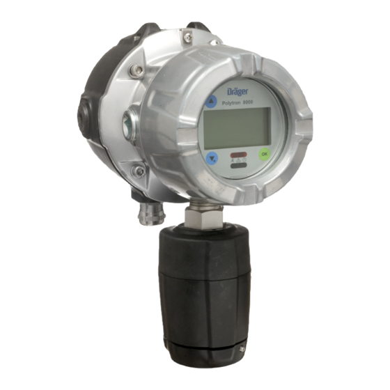
Page 6: Product Overview
3 Bucket with main electronics (and optional relay) 3 Bucket with main electronics (and optional relay) 4 Enclosure bottom 4 Enclosure bottom 5 Sensor 5 Sensor 6 Assembled instrument 6 Feed-through cable 7 Docking Station 8 Assembled instrument Dräger Polytron 8100... - Page 7 The instrument can be configured, calibrated and maintained WARNING non-intrusively without declassifying the area. Danger of explosions. Not to be used in oxygen enriched atmospheres. None of the Polytron 8000 instruments are certified and approved to be operated in oxygen enriched atmospheres. Dräger Polytron 8100...
- Page 8 230 to 500 Ω 18 to 30 V DC environmental conditions. HART Multidrop if stranded conductors are used, a ferrule must be used. operation 230 to 500 Ω 10 to 30 V DC Dräger Polytron 8100...
-
Page 9: Mechanical Installation
9-pin connector. Position the heat shrink tube at the edge of wire insulation and use a heat gun to shrink the tubing securely onto wire insulation. Slide rubber boot over the wires. 01033300.eps Dräger Polytron 8100... - Page 10 2 types of feed-through. 3 wire for power (part number 4544182) 9 wire for power and relay (part number 4544169) 3.6.1 Field wiring For field wiring of Docking Station refer to Instructions for use 9033242. Dräger Polytron 8100...
- Page 11 Screw the EC sensing head to the wall or pipe mount bracket (8) using screw and washer (6). NOTICE Pay attention to the orientation of the cable connector (9)! Select the appropriate protection cap (7) and place it on the screw. Dräger Polytron 8100...
- Page 12 Lock sensor adapter with bayonet ring. Attach the shield wire (15) to the ground lug of the enclosure. Tighten set-screw (2). Mandatory for Zone 22 installations. NOTICE The EC sensing head remote is automatically recognized by the instrument. Dräger Polytron 8100...
- Page 13 Insert the dongle in the slot with the Dräger logo facing upwards. Place bucket back into the enclosure. Screw the lid back on, until it is seated (see Section 10.8 on Page 42), and tighten set-screw. Switch power back on. Dräger Polytron 8100...
-
Page 14: Normal Operation
If no key is tapped within 30 seconds, the instrument will mode. After the alarm is acknowledged, the red LED will automatically return to normal operation. blink in single blink mode to indicate A1 is still active. Dräger Polytron 8100... -
Page 15: Menu Navigation
Factory default passwords: concentration graph, see Section 5.7.5 on Page 21. Calibration menu: _ _ _ 1 No changes can be made. Calibration and Settings menu: _ _ _ 2 1 Only displayed if relay is configured. Dräger Polytron 8100... -
Page 16: Menu
[OK] to validate the new parameter and return to the main menu. When exiting via “Back to menu” or “Previous”, all changes will be discarded. 4.4.4 Exiting the menu Tap [UP] to “Back to measurement” and tap [OK]. Dräger Polytron 8100... -
Page 17: Menu Overview
Beamblock on/off Beambl.-current page 23 Analog Offset page 24 Set current signal page 24 Set concentr. page 20 Set fault page 24 Set warning page 24 Set mainten. Set beamblock Parameter not used by Dräger Polytron 8000. Dräger Polytron 8100... -
Page 18: Information Instrument
Carefully review all Select Information > Sensor > Last cal. date and parameters and settings and confirm. confirm. 5.3.2 Display next calibration due date Select Information > Sensor > Next cal. date and confirm. Dräger Polytron 8100... -
Page 19: Settings Instrument
The current hysteresis is displayed. Set the hysteresis and confirm. Select Next and confirm. A confirmation screen shows all settings. Select Confirm and confirm with [OK]. The new settings are now saved. Repeat settings for A1 and A2. Dräger Polytron 8100... -
Page 20: Passwords
LED will automatically return 5.7.4 Language to their previous status. Select Settings > Instrument > Language and confirm. NOTICE Select the language from the list and confirm. When the relays are activated, alarm devices will be switched on. Dräger Polytron 8100... -
Page 21: Function Key
Alarm settings Passwords Language Function key HART interface Data-logger Analog interface Relay configuration Select Settings > Instrument > Device init. and confirm. Select Confirm and confirm with [OK]. Dräger Polytron 8100... -
Page 22: Settings Communication
Select Settings > Communication > HART interface > Tag and confirm. Select the line for editing the tag and confirm. Set the tag and confirm. Select Confirm and confirm with [OK]. Dräger Polytron 8100... - Page 23 During the test, the maintenance symbol [ ] is displayed. The static signal type is a constant current. However, the current value can be configured. The dynamic signal type is a square wave signal with the following characteristics. [mA] 0633300.eps Dräger Polytron 8100...
-
Page 24: Profibus Address
This can be prohibited if the sensor lock function (see This function sets the current to the maintenance current. Section 5.9.4 on Page 25) is activated. Select Settings > Communication > Analog interface > Set mainten. and confirm. Select Enable or Disable and confirm. Dräger Polytron 8100... -
Page 25: Auto Cal
Reset sensor This function resets all sensor parameters to the factory default settings (see Section 7 on Page 34). Select Settings > Sensor > Reset sensor required! and confirm. Select Confirm and confirm with [OK]. Dräger Polytron 8100... -
Page 26: Calibration Interval
This function periodically initiates the sensor self-test. Select Settings > Sensor > Set sensor-test and confirm. Select Enable or Disable and confirm. 5.9.10 Fast Response This function is only activated for Polytron 87X0 using the PIR 7X00 sensor. Dräger Polytron 8100... -
Page 27: Clear Data-Logger
Select On or Off and confirm. Measurements will be stored if they exceed a turned threshold beyond the trigger value (relative to the last stored value). Measurements within the sampling time will turned be stored. Dräger Polytron 8100... -
Page 28: Maintenance
This method of target gas calibration is more accurate than a surrogate gas calibration. A surrogate gas calibration may only be performed as an alternative if a target gas calibration is not possible. The sensor should be fully warmed-up (see sensor data sheet). Dräger Polytron 8100... -
Page 29: Zero Calibration
The instrument returns to the calibration menu. the sensor or disconnect tubing. If the current value is not within the alarm range: Select Next and confirm. The instrument returns to the calibration menu. A calibration can be aborted at any time. Dräger Polytron 8100... -
Page 30: Auto Calibration
Select Conc. and confirm. Set the concentration of the calibration gas. If the settings are correct: Apply calibration gas. Select Next and confirm to start the calibration. Select Back to menu to abort the calibration. Dräger Polytron 8100... -
Page 31: Troubleshooting
(see Section 5.9.3 on Page 25). connected. #105 Instrument fault. Have the instrument checked by DrägerService. #137 Instrument fault. Cycle power. If this fault occurs again: Have the instrument checked by DrägerService. ® DrägerService is a registered trademark of Dräger. Dräger Polytron 8100... -
Page 32: Warning Reference
Sensor warm-up phase has not ended. Wait until the sensor has warmed up. Do not calibrate before #165 Increased measurement error must be sensor is fully warmed-up. expected. #167 Calibration interval expired. Recalibrate the instrument (see Section 6.2 on Page 28). #170 Dräger Polytron 8100... -
Page 33: Replacing The Sensor
This identifies the gas type from a distance, even if the power has failed. Calibrate instrument, if necessary (see Section 6.2 on Page 28). Check the installation requirements and instrument for SIL status (see Section 5.6 on Page 18). Dräger Polytron 8100... -
Page 34: Factory Default Settings
0 to 3.5 mA Analog offset 0 mA - 0.2 to 1.5 mA HART address 0 to 15 Auto-calibration On / Off Calibration interval Depending on sensor 0 to 720 Function key Faults Graph, fault, warning, vitality, bump test Dräger Polytron 8100... -
Page 35: Fixed Settings
Alarm Hierarchy it triggers A1 and A2: acknowledging will cause the A1 relay to release. However, the red LED will still double blink as long as the A2 condition continues to exist. Dräger Polytron 8100... -
Page 36: Sensor Principle
Danger of explosions! Do not dispose sensors in fire, risk of chemical burns! Do not open with force. Observe applicable local waste disposal regulations. For information, consult your local environmental agency, local government offices or appropriate waste disposal companies. Dräger Polytron 8100... -
Page 37: Technical Data
20.7 to 38.4 in. Hg (700 to1300 hPa) Humidity 10 to 95 %RH, non-condensing Temperature -5 to +40 °C, short term -20 to +55 °C Storage humidity 30 to 70 %RH, non-condensing Storage temperature 0 to +40 °C Dräger Polytron 8100... - Page 38 If the sensor is exposed to higher concentrations (> 1 Vol%) over several days, these substances could cause a sensor drift which might reduce the calibration interval. However, these will not reduce the sensor service life. Dräger Polytron 8100...
-
Page 39: Din En 50104 For Drägersensor O2Ls (6809630)
Response time < 12 seconds 0...20 < 30 seconds 0...90 Calibration Flow rate 0.5 L/min Zero gas Nitrogen (99.9 Vol% N Target gas Oxygen / Nitrogen gas mixture Warm-up time Operation < 90 minutes Calibration < 6 hours Dräger Polytron 8100... - Page 40 30 ppm no influence tetrahydrofurane 60 ppm no influence tetrahydrothiophene 5 ppm no influence vinyl chloride 50 ppm no influence 1.5 (–) * hydrogen 1 Vol% hydrogen peroxide 5 ppm no influence (–) * Negative display Dräger Polytron 8100...
-
Page 41: Marking
10.7 Environmental influences Maintenance signal 3.4 mA steady signal or 1 Hz For influences on the measurement performance and modulation between 3 and restrictions of a particular sensor see sensor data sheet. 5 mA (selectable) 10.3.2 HART digital communication Dräger Polytron 8100... -
Page 42: Tightening Torque For Instrument Threads
Wire size Wire size Lb. In. Power supply 4.4 - 7.0 24 - 12 0.2 - 2.5 and signal (0.5 - 0.8 Nm) 4.4 - 7.0 Relay 20 - 12 0.5 - 2.5 (0.5 - 0.8 Nm) Dräger Polytron 8100... -
Page 43: Declaration Of Conformity
Declaration of Conformity Declaration of Conformity Dräger Polytron 8100... -
Page 44: Control Drawing
Control Drawing Control Drawing Dräger Polytron 8100... -
Page 45: Dräger Polytron
Control Drawing Dräger Polytron 8100... - Page 48 Dräger Safety AG & Co. KGaA Revalstraße 1 23560 Lübeck, Germany Tel +49 451 882 0 Fax +49 451 882 20 80 www.draeger.com 9033301 © Dräger Safety AG & Co. KGaA Edition 07 - September 2015 (Edition 01 - February 2012) Subject to alteration...
Need help?
Do you have a question about the Polytron 8100 and is the answer not in the manual?
Questions and answers
I'm trying to get the wiring diagram and terminals for the Polytron 8100
For the Dräger Polytron 8100, the electrical connection for the fieldbus interface involves the following steps and terminal details:
1. Remove the lid and pull out the PCB unit containing the main electronics.
2. Disconnect the 2-pin (power) and 4-pin (signal) connectors.
3. Connect:
- Two wires for power to the 2-pin connector:
- Pin 1: PWR+
- Pin 2: PWR–
- Four wires for signal to the 4-pin connector, as indicated in wiring diagrams (Figure H or I, not provided here).
4. Fasten terminal screws using the correct torque (refer to Section 10.10 on Page 44).
5. Reconnect the connectors and secure them.
6. Cover the connector with the rubber boot.
Ensure an alarm device is connected to the fault relay for fault recognition.
This answer is automatically generated