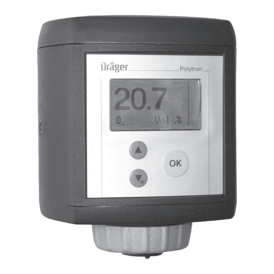
Dräger Polytron 7000 Instructions For Use Manual
Transmitter for electrochemical sensors
Hide thumbs
Also See for Polytron 7000:
- Instructions for use manual (148 pages) ,
- Manual (12 pages) ,
- Installation instructions manual (8 pages)


Need help?
Do you have a question about the Polytron 7000 and is the answer not in the manual?
Questions and answers