
Related Manuals for Dräger Polytron Ex


Summary of Contents for Dräger Polytron Ex
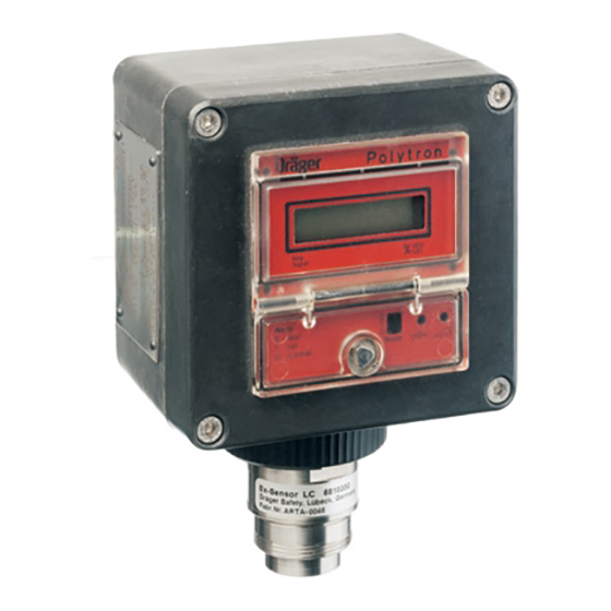
- Page 1 Polytron Transmitter Ex and Ex R Instructions for Use Page 1 of 40 9023744 - 3rd edition - October 2005...
-
Page 2: Table Of Contents
........... . . 12 Connection between Transmitter Polytron Ex R and Sensing Head SE Ex . - Page 3 ............24 Transmitter Polytron Ex and Ex R .
-
Page 4: For Your Safety
For Your Safety For Your Safety Strictly follow the Instructions for Use Any use of the instrument requires full understanding and strict observation of these instructions. The instrument is only to be used for purposes specified here. Maintenance The transmitter must be inspected and serviced regularly by trained service per- sonnel. -
Page 5: Intended Use
— Transmitter with 4 to 20 mA interface enabling 3- or 4-wire technique. — Transmitter Polytron Ex R (R = Remote) with remote sensing head SE Ex for ap- plications where sensing head and transmitter have to be placed at different loca- tions. -
Page 6: Device Concept
— Transmitter Polytron Ex with Ex-sensor PR M — Transmitter Polytron Ex with Ex-sensor LC M Transmitter Polytron Ex R with remote sensing head SE Ex to be used in applications where the point of detection is not easily accessible for the user: —... -
Page 7: Hints For Safe Use
Only an Ex-sensor approved by its own is allowed to be connected to the terminals K11, K12 und K13 of the transmitter Polytron Ex. Installing the Ex-sensor it has to be ensured that a protection class of at least IP 20 acc. to EN 60 529 is maintained. - Page 8 — Sensor replacement and maintenance is possible without switching off the supply voltage. The transmitters Polytron Ex resp. Polytron Ex R with sensing head SE Ex is marked by the device category II 2G and is suitable to be operated in hazardous zones 1 and 2.
-
Page 9: Installing Transmitters Polytron Ex Resp. Ex R
Transmitter Polytron Ex resp. Sensing Head SE Ex: Pay attention to density of gas! — In case of gases, the density of which is lower than that of air, such as hydrogen, methane or ammonia the transmitter resp. -
Page 10: Mounting Of The Transmitter Polytron Ex R
Mount at an accessible place Observe maximum length of 10 m of the pre-conditioned connection cable bet- ween sensing head SE Ex and transmitter Polytron Ex R. Mount with four screws through the housing by means of the mounting brackets. -
Page 11: Installing Electrical Connections
Installing Electrical Connections Installing Electrical Connections Connection between Transmitter and Central Unit Remark: — The cable gland is suitable for cable diameters from 7 to 12 mm and must only be used for fixed installations. — Routing and connecting the electrical installation must only be done by trained personnel, observing appropriate regulations –... -
Page 12: 4-Wire Connection
Installing Electrical Connections 4-Wire Connection 1 Remove dummy plug. 2 Screw second cable gland (see Order List, page 31) into housing and secure with nut. Important: The cable gland is a part of the approved device and only the one listed in the Order List is allowed to be used. -
Page 13: Connection Between Transmitter Polytron Ex R And Sensing Head Se Ex
Installing Electrical Connections Connection between Transmitter Polytron Ex R and Sensing Head SE Ex Make sure to use such Ex-sensors only which are listed in the Order List, page 31. Shorten the cable if required, and attach it in line with the illustration: brown –... -
Page 14: Adjustment Of Constant Current
Installing Electrical Connections Adjustment of Constant Current (ex-factory-setting: 270 mA) Note: The procedure is valid for the transmitter Polytron Ex and Ex R, however the illustra- brown tion only shows the transmitter Polytron Ex. yellow 1 Check position of jumper and correct if required (ex-factory setting). -
Page 15: Start-Up
(see page 8, para. 3). Allow transmitter with Ex-sensor to warm-up in this condition for 10 minutes (sensor warm-up time). Calibrating Transmitter Polytron Ex Use special key to open flap in front of adjusters. 1 Set sliding switch to position »1« = cal. -
Page 16: Following Completion Of Calibration
Supply clean air at a rate of approx. 0.5 L/min. via the calibration adapter. 2 Wait for the display on the transmitter Polytron Ex R to stabilize (max. 3 minutes). Set potentiometer of the transmitter Polytron Ex R such that the display indicates 00.0. -
Page 17: Sensitivity Adjustment
Test gas Once measured value display has stabilized (after max. 3 minutes): 1 Adjust sensitivity on potentiometer of the transmitter Polytron Ex R such that dis- play indicates the calibration gas concentration. When using the sensing head SE Ex LC M: —... -
Page 18: Check The Measured Value Output
Test gas Perform zero calibration as described under “Calibrating Transmitter Polytron Ex” resp. “Calibrating Transmitter Polytron Ex R" (page 15 resp. page 16). 1 Set sliding switch to position »2« = test. The measurement signal of the 4 to 20 mA loop oscillates between 2.5 and 5 mA with approx. -
Page 19: Following Completion Of Test
Start-Up Following Completion of Test: 1 Set sliding switch to position »0« = normal. Use special key to close flap in front of adjusters. Page 19 of 40 9023744 - 3rd edition - October 2005... -
Page 20: Operational Use
Operational Use Operational Use 1 The display indicates the measured gas concentration, 2 when the sliding switch is set to »0« = normal and »1« = cal. — A reference number for the constantly amplified sensor signal is indicated when the switch is set to »2«... -
Page 21: Maintenance
Maintenance Maintenance EN 50073 and national regulations applicable must be observed. Every day Visual inspection to check that it is operational. When using for the first time Check the zero adjustment and sensitivity calibration, see page 15 to page 17. Check that display on the transmitter matches the display on the central unit. -
Page 22: Ex-Sensor Replacement
— If the sensing head is not to be replaced by a sensing head with the same sensor current or sensor voltage (see page 25), the procedure to be employed is descri- bed in the section entitled “Connection between transmitter Polytron Ex R and sensing head SE Ex”. -
Page 23: Fault - Cause - Remedy
Fault – Cause – Remedy Fault – Cause – Remedy Fault Cause Remedy No Display Cable faulty Check cable to central controller. Transmitter resp. sensing head can no Ex-sensor faulty or poisoned Replace Ex-sensor, page 22. longer be calibrated Measurement current fluctuates with Sliding switch set to "1"... -
Page 24: Technical Data
Technical Data Technical Data Transmitter Polytron Ex and Ex R Measuring range 0 to 99 %LEL (LEL: Lower Explosive Limit) Resolution of the digital display 1 % LEL, and 0.1 % LEL in calibration mode Measurement current 4 mA to 20 mA... -
Page 25: Ex-Sensors
Technical Data Safety relevant parameters: Power supply circuit max. 32 V DC (terminals K1, K2, K3 and K4): Sensor output current circuit (terminals K11, K12 and K13): Nominal voltage max. 7.6 V DC Current max. 2350 mA Power max. 3.23 W Max. -
Page 26: Sensing Heads Se Ex
Technical Data Sensing Heads SE Ex Sensing head SE Ex PR M Part number 68 09 758 Operational parameters Constant current, sensor current: 270 mA Voltage at test points 891 mV Device description acc. to Directive 94/9/EC Dräger Safety, D-23560 Lübeck, Germany Type SE Ex PR M ET II 2G EEx de IIC T4/T5/T6 DMT 97 ATEX E 006X... -
Page 27: Measuring Other Gases And Vapours
Column 4: In the case of the Polytron Ex calibrated to the substance shown (in column 1), the display in the 0 to 70 % LEL range varies from the actual concentration of the substance by not more than the value indicated here. -
Page 28: Transmitter Ex / Ex R
Technical Data Transmitter Ex / Ex R 106 mm Page 28 of 40 9023744 - 3rd edition - October 2005... -
Page 29: Sensing Head Se Ex
Technical Data Sensing Head SE Ex 68 mm Page 29 of 40 9023744 - 3rd edition - October 2005... -
Page 30: Design And Mode Of Operation
The transmitter Polytron Ex consists of a housing, an Ex-sensor and the corres- ponding electronics. The transmitter Polytron Ex R consists of a housing with electronics and a sensing head including an Ex-sensor, installed at a maximum distance of 10 m. -
Page 31: Order List
(measuring range 0 to 99 %LEL) Ex-sensor LC M 68 10 350 (measuring range 0 to 9.9 %LEL) Transmitter Polytron Ex R 83 17 509 with 10 m sensor cable Sensing head SE Ex PR M ET 68 09 758... -
Page 32: Ec Type-Examination Certificate Bvs 03 Atex E 160
EC Type-Examination Certificate BVS 03 ATEX E 160 X EC Type-Examination Certificate BVS 03 ATEX E 160 X Page 32 of 40 9023744 - 3rd edition - October 2005... - Page 33 EC Type-Examination Certificate BVS 03 ATEX E 160 X Page 33 of 40 9023744 - 3rd edition - October 2005...
- Page 34 Page 34 of 40 9023744 - 3rd edition - October 2005...
- Page 35 EC Type-Examination Certificate BVS 03 ATEX E 160 X Page 35 of 40 9023744 - 3rd edition - October 2005...
-
Page 36: Declaration Of Conformity
Declaration of Conformity Declaration of Conformity Page 36 of 40 9023744 - 3rd edition - October 2005... -
Page 37: Index
Calibrating Transmitter Polytron Ex ........ - Page 38 Transmitter Polytron Ex with Ex-sensor LC M ....... . 6...
- Page 39 Index Transmitter Polytron Ex R with sensing head SE Ex LC M ....6 Transmitter Polytron Ex R with sensing head SE Ex PR M ET ....6 Transmitter with measurement function for explosion protection according to 94/9/EC .
Need help?
Do you have a question about the Polytron Ex and is the answer not in the manual?
Questions and answers