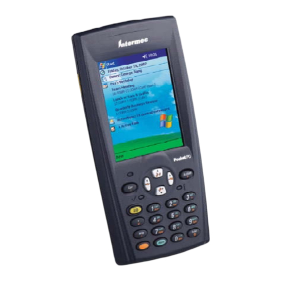
Intermec 700 Series User Manual
Color mobile computer
Hide thumbs
Also See for 700 Series:
- User manual (480 pages) ,
- Quick start manual (36 pages) ,
- Instructions manual (6 pages)
Table of Contents
Advertisement
Quick Links
Advertisement
Table of Contents

Subscribe to Our Youtube Channel
Related Manuals for Intermec 700 Series


Summary of Contents for Intermec 700 Series
- Page 1 User’s Manual 700 Series Color Mobile Computer...
- Page 2 User’s Manual 700 Series Color Mobile Computer...
- Page 3 The information contained herein is proprietary and is provided solely for the purpose of allowing customers to operate and service Intermec manufactured equipment and is not to be released, reproduced, or used for any other purpose without written permission of Intermec.
-
Page 4: Table Of Contents
Introduction About the 700 Series Color Mobile Computer .......... - Page 5 ............Enter Information on Your 700 Series Computer .
- Page 6 ............Getting Books on Your 700 Series Computer .
- Page 7 ............SNMP Configuration on the 700 Series Computer .
- Page 8 ......... . 700 Series Color Mobile Computer User’s Manual...
- Page 9 IS9CConfig::SetStandard2of5 ....... viii 700 Series Color Mobile Computer User’s Manual...
- Page 10 ............700 Series Color Mobile Computer User’s Manual...
- Page 11 ..........700 Series Color Mobile Computer User’s Manual...
-
Page 12: Codabar
......... 700 Series Color Mobile Computer User’s Manual... -
Page 13: Automatic Shutoff
........... . . 700 Series Color Mobile Computer User’s Manual... - Page 14 ............... . 700 Series Color Mobile Computer User’s Manual...
- Page 15 Contents 700 Series Color Mobile Computer User’s Manual...
-
Page 16: Before You Begin
Intermec support services organization. In the U.S. call 1-800-755-5505, and in Canada call 1-800-668-7043. If you live outside of the U.S. or Canada, you can find your local Intermec support services organization on the Intermec Web site at www.intermec.com. -
Page 17: Warnings, Cautions, And Notes
About This Manual The 700 Series Color Mobile Computer User’ s Manual provides you with information about the features of the 700 Series Color Mobile Computer and how to configure, troubleshoot, and support it. You must be familiar with your host PC, your network, and your other Intermec equipment. -
Page 18: Format Conventions For Input From A Keyboard Or Keypad
S Appendix C — Bar Codes Describes some of the more common bar code symbologies and includes bar code labels that can be scanned to configure your 700 Series Com- puter. Format Conventions for Input From a Keyboard or Keypad This table describes the formatting conventions for input from PC or host computer keyboards and device keypads. -
Page 19: Related Publications
Before You Begin Related Publications To order printed versions of the Intermec manuals, contact your local In- termec representative or distributor. Following are related Intermec manuals, CD-ROMs, and part numbers (P/N). For other versions and languages, consult your Intermec sales representative. -
Page 20: Introduction
Introduction This chapter introduces the 700 Series Color (700C) Mobile Computer, developed by Intermec Technologies Corporation to enhance wireless con- nectivity needs. 700 Series Color Mobile Computer User’s Manual... -
Page 21: About The 700 Series Color Mobile Computer
The 700 Series Computer comes equipped with a nominal 14.4 Watt-hour, 7.2V (two 2000 mAh cells), replaceable Lithium-Ion (LiIon) battery. To view the status of this battery from the 700 Series Computer, tap Start → Settings → the System tab → the Power icon to view the current status of both the main battery and the backup battery. -
Page 22: Low Battery Shutdown
700 Series Computer if Intermec Content is enabled, the Plus region is enabled and installed, and a laser scanner is installed. You can also view the battery status for the 700 Series Computer by accessing the Unit Information control panel applet. Tap the Unit Information icon, then tap the Battery Status tab to view the current status. -
Page 23: System Status Maintained
700 Color Mgmt Tools\Cab Files” will be the default directory. There are folders within the “\Cab Files” directory that contain demos and pro- gram files. See the 700 Series Color Software Tools CD User’ s Manual for more information about these files. -
Page 24: Removeable Card Support
Introduction Removeable Card Support To access either the CompactFlash (CF) or SecureDigital (SD) card slot, locate the access door at the top of the 700 Series Computer, remove its two screws, then remove the door. CompactFlash Cards Support is limited to one CompactFlash (CF) Storage Card in the 700 Se- ries Computer, either for storage or for the 802.11b radio. -
Page 25: What' S New
Chapter — Introduction You can also view the latest software build version on your 700 Series Computer by accessing the Unit Information control panel applet. Select Start → Settings → the System tab → the Unit Information icon → the Versions tab to view the current build version on your 700 Series Computer. - Page 26 Pocket PC 2002 This chapter introduces the Pocket PC 2002 operating system from Microsoft Corporation. 700 Series Color Mobile Computer User’s Manual...
-
Page 27: Introduction
Introduction Congratulations on purchasing a Pocket PC. Due to the size and capabili- ties of this 700 Series Color Mobile Computer, you can keep your most important business and personal information up-to-date and close at hand. Microsoft ActiveSync increases the power of your 700 Series Computer by allowing you to synchronize the information on your desktop or laptop computer with your 700 Series Computer. - Page 28 Windows Media Player for Pocket PC (page 57) Microsoft Reader (page 58) Pocket Internet Explorer (page 62) Note: Components marked with “RAM” are provided on a Companion CD for download into RAM rather than burned into Flash ROM. 700 Series Color Mobile Computer User’s Manual...
-
Page 29: Where To Find Information
Where to Find Information This chapter describes your 700 Series Computer hardware, provides an overview of the programs on your 700 Series Computer, and explains how to connect your 700 Series Computer to a desktop computer, a network, or the Internet. For instructions on setting up your 700 Series Computer and installing ActiveSync, see the Quick Start Card. -
Page 30: Basic Skills
Today Screen When you turn on your 700 Series Computer for the first time each day (or after four hours of inactivity), you will see the Today screen. You can also display it by tapping the Start flag (shown left) and then Today. On the Today screen, you can see at a glance important information for the day. - Page 31 Notification of one or more e-mail messages received. If more notification icons need to be displayed than there is room to display them, the Notification icon (shown left) will display. Tap the icon to view all notification icons. 700 Series Color Mobile Computer User’s Manual...
-
Page 32: Programs
Drag the stylus off the label so that the command is not carried out. The following is a partial list of programs that are on your 700 Series Computer. Look on the Pocket PC Companion CD for additional pro- grams that you can install onto your 700 Series Computer. -
Page 33: Navigation Bar And Command Bar
Panel button. To create a new item in the current program, tap New. To see the name of a button, tap and hold the stylus on the button. Drag the stylus off the button so that the command is not carried out. 700 Series Color Mobile Computer User’s Manual... -
Page 34: Pop-Up Menus
Notifications Your 700 Series Computer reminds you in a variety of ways when you have something to do. For example, if you have set up an appointment in Calendar, a task with a due date in Tasks, or an alarm in Clock, you will be notified in any of the following ways: S A message box appears on the screen. -
Page 35: Enter Information On Your 700 Series Computer
S Write directly on the screen. S Draw pictures on the screen. S Speak into your 700 Series Computer microphone to record a message. S Use Microsoft ActiveSync to synchronize or copy information from your desktop computer to your 700 Series Computer. For more infor- mation on ActiveSync, see ActiveSync Help on your desktop computer. -
Page 36: Typing With The Soft Keyboard
— Pocket PC 2002 When you use the input panel, your 700 Series Computer anticipates the word you are typing or writing and displays it above the input panel. When you tap the displayed word, it is inserted into your text at the insertion point. -
Page 37: Using Letter Recognizer
You can cut, copy, and paste text by tapping and holding the selected words and then tapping an editing command on the pop-up menu, or by tapping the command on the Edit menu. 700 Series Color Mobile Computer User’s Manual... -
Page 38: Writing On The Screen
You can cut, copy, and paste written text in the same way you work with typed text: tap and hold the selected words and then tap an editing com- mand on the pop-up menu, or tap the command on the Edit menu. 700 Series Color Mobile Computer User’s Manual... -
Page 39: Converting Writing To Text
If you want to convert only certain words, select them before tapping Rec- ognize on the Tools menu (or tap and hold the selected words and then tap Recognize on the pop-up menu). If a word is not recognized, it is left as writing. 700 Series Color Mobile Computer User’s Manual... - Page 40 S Write the letters of a word closely and leave big gaps between words so that the 700 Series Computer can easily tell where words begin and end. S Hyphenated words, foreign words that use special characters such as ac- cents, and some punctuation cannot be converted.
-
Page 41: Drawing On The Screen
Edit menu. To resize a drawing, make sure the Pen button is not selected, and drag a selection handle. 700 Series Color Mobile Computer User’s Manual... -
Page 42: Recording A Message
1 Hold your computer’ s microphone near your mouth or source of sound. 2 Press and hold the Record hardware button on your 700 Series Com- puter until you hear a beep. 3 While holding down the Record button, make your recording. -
Page 43: Using My Text
Note: You can add text after inserting a My Text message before sending To edit a My Text message, in the Tools menu, tap Edit My Text Mes- → sages. Select the message you wish to edit and make desired changes. 700 Series Color Mobile Computer User’s Manual... -
Page 44: Finding And Organizing Information
Note: To quickly find information that is taking up storage space on your 700 Series Computer, select Larger than 64 KB in Type. You can also use the File Explorer to find files on your 700 Series Comput- er and to organize these files into folders. Tap Start → Programs →... -
Page 45: Customizing Your 700 Series Computer
You can install any program created for your 700 Series Computer, as long as your 700 Series Computer has enough memory. The most popular place to find software for your 700 Series Computer is on the Pocket PC Web site (http://www.microsoft.com/mobile/pocketpc). - Page 46 S If the file is not an installer, you will see an error message stating that the program is valid but it is designed for a different type of comput- er. You will need to move this file to your 700 Series Computer. If you cannot find any installation instructions for the program in the...
- Page 47 My Documents by default, and then My Device to see a list of all folders on the 700 Series Computer). Tap and hold the program and tap Cut on the pop-up menu. Open the Start Menu fold- er located in the Windows folder, tap and hold a blank area of the win- dow, and tap Paste on the pop-up menu.
-
Page 48: Microsoft Activesync
Tasks on your 700 Series Computer. You will notice that information you have stored in Microsoft Outlook on your desktop computer has been copied to your 700 Series Computer, and you did not have to type a word. Disconnect your 700 Series Computer from your computer and you are ready to go! 700 Series Color Mobile Computer User’s Manual... - Page 49 Once you have set up ActiveSync and completed the first synchronization process, you can initiate synchronization from your 700 Series Computer. To switch to ActiveSync on your 700 Series Computer, tap Start → ActiveSync. Note that if you have a wireless LAN card, you can synchronize remotely from your 700 Series Computer.
-
Page 50: Microsoft Pocket Outlook
Computer. You can also synchronize this information directly with a Microsoft Exchange server. Each time you synchronize, ActiveSync compares the changes you made on your 700 Series Computer and desk- top computer or server and updates both computers with the latest in- formation. -
Page 51: Creating An Appointment
Thoughts and Ideas” on page 40. 7 When finished, tap OK to return to the calendar. Note: If you select Remind me in an appointment, your 700 Series Com- puter will remind you according to the options set in Start → Settings →... -
Page 52: Using The Summary Screen
The meeting notice is created automatically and placed in the Outbox folder. For more information on sending and receiving meeting requests, see Cal- endar Help and Inbox Help on the 700 Series Computer. 700 Series Color Mobile Computer User’s Manual... -
Page 53: Contacts: Tracking Friends And Colleagues
Contacts maintains a list of your friends and colleagues so that you can easily find the information you are looking for, whether you are at home or on the road. Using the 700 Series Computer infrared (IR) port, you can quickly share Contacts information with other 700 Series Computer users. -
Page 54: Finding A Contact
View → By Company. The number of contacts that work for that company will be displayed to the right of the company name. S Tap Start → Find, enter the contact name, select Contacts for the type, and then tap Go. 700 Series Color Mobile Computer User’s Manual... -
Page 55: Using The Summary Screen
Chapter — Pocket PC 2002 Using the Summary Screen When you tap a contact in the contact list, a summary screen is displayed. To change the contact information, tap Edit. 700 Series Color Mobile Computer User’s Manual... -
Page 56: Tasks: Keeping A To Do List
Pocket PC 2002 Tasks: Keeping a To Do List Use Tasks to keep track of what you have to do. Note: To change the way information is displayed in the list, tap Tools → Options. 700 Series Color Mobile Computer User’s Manual... -
Page 57: Creating A Task
6 When finished, tap OK to return to the task list. Note: To quickly create a task with only a subject, tap Entry Bar on the Tools menu. Then, tap Tap here to add a new task and enter your task information. 700 Series Color Mobile Computer User’s Manual... -
Page 58: Using The Summary Screen
Chapter 2 — Pocket PC 2002 Using the Summary Screen When you tap a task in the task list, a summary screen is displayed. To change the task, tap Edit. 700 Series Color Mobile Computer User’s Manual... -
Page 59: Notes: Capturing Thoughts And Ideas
If a note is open when you create the record- ing, it will be included in the note as an icon. If the note list is displayed, it will be created as a stand-alone recording. 700 Series Color Mobile Computer User’s Manual... -
Page 60: Creating A Note
2 Create your note by writing, drawing, typing, and recording. For more information about using the input panel, writing and drawing on the screen, and creating recordings, see “Basic Skills” on page 11. 700 Series Color Mobile Computer User’s Manual... -
Page 61: Inbox: Sending And Receiving E-Mail Messages
Messages that you receive directly from an e-mail server are linked to your e-mail server rather than your desktop computer. When you delete a mes- sage on your 700 Series Computer, it is also deleted from the e-mail server the next time you connect based on the settings selected in ActiveSync. -
Page 62: Using The Message List
Chapter 2 — Pocket PC 2002 Using the Message List Messages you receive are displayed in the message list. By default, the most recently received messages are displayed first in the list. 700 Series Color Mobile Computer User’s Manual... - Page 63 For more information, see ActiveSync Help. S Change options for direct e-mail server connections in Inbox on your 700 Series Computer. Tap Tools → Options → the Service tab, then tap the service you want to change. Tap and hold the service and select Delete to remove a service.
-
Page 64: Composing Messages
If you are sending an SMS message and want to know if it was received, tap Edit → Options → Request SMS text message delivery notification before sending the message. 700 Series Color Mobile Computer User’s Manual... -
Page 65: Managing E-Mail Messages And Folders
The folders you create and the e-mail messages you move are mirrored on the server. Therefore, messages are available to you anytime you con- nect to your mail server, whether it is from your 700 Series Computer or desktop computer. This synchronization of folders occurs whenever you connect to your mail server, create new folders, or rename/delete folders when connected. -
Page 66: Companion Programs
The companion programs consist of Microsoft Pocket Word, Microsoft Pocket Excel, Windows Media Player for Pocket PC, and Microsoft Reader. To switch to a companion program on your 700 Series Computer, tap Start → Programs, then tap the program name. - Page 67 — Pocket PC 2002 Pocket Word contains a list of the files stored on your 700 Series Comput- er. Tap a file in the list to open it. To delete, make copies of, and send files, tap and hold a file in the list. Then, select the appropriate action on the pop-up menu.
-
Page 68: Typing Mode
Word document, using your stylus instead of the mouse to drag through the text you want to select. You can search a document to find text by tapping Edit → Find/Replace. 700 Series Color Mobile Computer User’s Manual... -
Page 69: Writing Mode
“Drawing Mode” on the next page. Written words are converted to graphics (metafiles) when a Pocket Word document is converted to a Word document on your desktop computer. 700 Series Color Mobile Computer User’s Manual... -
Page 70: Drawing Mode
In recording mode, embed a recording into your document. Recordings are saved as .WAV files. For more information on recording, see “Basic Skills” on page 11. For more information on using Pocket Word, tap Start → Help. 700 Series Color Mobile Computer User’s Manual... -
Page 71: Pocket Excel
Pocket Excel (.PXL) and Excel (.XLS). Pocket Excel contains a list of the files stored on your 700 Series Comput- er. Tap a file in the list to open it. To delete, make copies of, and send files, tap and hold a file in the list. -
Page 72: Tips For Working In Pocket Excel
MSN Messenger Note: MSN Messenger is only available on the Premium Edition of Pocket PC 2002. MSN Messenger on your 700 Series Computer is an instant messaging program that lets you: S See who is online. S Send and receive instant messages. -
Page 73: Setting Up
3 To sign in, tap the sign-in screen and enter your e-mail address and pass- word. Note: If you already use MSN Messenger on your desktop computer, your contacts will show up on your 700 Series Computer without being added again. Working with Contacts The MSN Messenger window shows all of your messenger contacts at a glance, divided into Online and Not Online categories. -
Page 74: Chatting With Contacts
Note: To switch back to the main window without closing a chat, tap the Contacts button. To revert back to your chat window, tap Chats and select the person whom you were chatting with. 700 Series Color Mobile Computer User’s Manual... - Page 75 Pocket PC 2002 To know if the contact you are chatting with is responding, look for the message under the text entry area. For more information on using MSN Messenger, tap Start → Help. 700 Series Color Mobile Computer User’s Manual...
-
Page 76: Windows Media Player For Pocket Pc
Use Microsoft Windows Media Player for Pocket PC to play digital audio and video files that are stored on your 700 Series Computer or on a net- work. To switch to Windows Media Player for Pocket PC, tap Start →... -
Page 77: Microsoft Reader
Pocket PC 2002 Microsoft Reader Use Microsoft Reader to read eBooks on your 700 Series Computer. Download books to your desktop computer from your favorite eBook Web site. Then, use ActiveSync to copy the book files to your activated 700 Se- ries Computer. -
Page 78: Using The Library
Using the Library The Library is your Reader home page; it displays a list of all books stored on your 700 Series Computer or storage card. To open the Library: 1 On the Reader command bar, tap Library. 2 On a book page, tap the book title, then tap Library on the pop-up menu. -
Page 79: Reading A Book
In addition to the text, each book page includes a page number and book title. You can also page through a book by using the Up/Down control on your 700 Series Computer. 700 Series Color Mobile Computer User’s Manual... -
Page 80: Using Reader Features
Removing a Book When you finish reading a book, you can delete it to conserve space on your 700 Series Computer. If a copy of the book is stored on your desktop computer, you can download it again at any time. -
Page 81: Pocket Internet Explorer
Unless you mark the favorite link as a mobile favorite, only the link will be downloaded to your 700 Series Computer, and you will need to connect to your ISP or network to view the content. For more information on synchronization, see ActiveSync Help on the desktop computer. - Page 82 Properties. In the Download tab, specify the number of links deep you want to download. To conserve 700 Series Computer memory, go only one level deep. 6 Synchronize your 700 Series Computer and desktop computer. Mobile favorites that are stored in the Mobile Favorites folder in Internet Ex- plorer are downloaded to your 700 Series Computer.
-
Page 83: Using Avantgo Channels
1 In ActiveSync options on the desktop computer, turn on synchroniza- tion for the AvantGo information type. 2 In Pocket Internet Explorer on your 700 Series Computer, tap the Fa- vorites button to display your list of favorites. 3 Tap the AvantGo Channels link. -
Page 84: Using Pocket Internet Explorer
Using Pocket Internet Explorer You can use Pocket Internet Explorer to browse mobile favorites and chan- nels that have been downloaded to your 700 Series Computer without connecting to the Internet. You can also connect to the Internet through an ISP or a network connection and browse the Web. -
Page 85: Viewing Mobile Favorites And Channels
You will see the page that was downloaded the last time you synchronized with your desktop computer. If the page is not on your 700 Series Com- puter, the favorite will be dimmed. You will need to synchronize with your desktop computer again to download the page to your 700 Series Comput- er, or connect to the Internet to view the page. -
Page 86: Getting Connected
700 Series Computers as well as your desktop computer, a network, or the Internet. You have the following connection options: S Use the infrared (IR) port on your 700 Series Computer to send and receive files between two 700 Series Computers. If this is the method you want to use, see “Transferring Items Using Infrared”... -
Page 87: Connecting To An Internet Service Provider
S Password S TCP/IP settings 2 If your 700 Series Computer does not have a built-in modem, install a modem card, or use or use a NULL modem cable and appropriate adapters to connect an external modem to your 700 Series Computer through the serial port. -
Page 88: Creating An Ethernet Connection To An Isp
“MSN Messenger” on page 53. Creating an Ethernet Connection to an ISP 1 You do not need to create a new connection on your 700 Series Com- puter. Instead, you must purchase a dock to enable on-board Ethernet or purchase a CompactFlash Ethernet card that is compatible with your 700 Series Computer. -
Page 89: Connecting To Work
S Password S Domain name S TCP/IP settings 2 If your 700 Series Computer does not have a built-in modem, install a modem card. 3 Tap Start → Settings → the Connections tab → Connections. Under The Internet settings, select Internet Settings and tap Modify. -
Page 90: Creating An Ethernet Connection To Work
Creating an Ethernet Connection to Work 1 You do not need to create a new connection on your 700 Series Com- puter. Instead, you must purchase a dock to enable on-board Ethernet or purchase a CompactFlash Ethernet card that is compatible with your 700 Series Computer. -
Page 91: Ending A Connection
5 Connect the Ethernet card or dock to the network by using a network cable. For information, see your owner’ s manual. 6 To synchronize your 700 Series Computer, tap Start → ActiveSync. In the Tools menu, tap Options. → the PC tab, select Include PC when synchronizing remotely and connect to, and select your computer’... -
Page 92: Setting Up An E-Mail Service
Pocket PC 2002 Setting Up an E-mail Service S In Inbox on your 700 Series Computer, tap Services → New Service. Follow the directions in the New Service wizard. For an explanation of a screen, tap Start → Help. When finished, to con- nect to your e-mail server, tap Services →... - Page 93 Chapter — Pocket PC 2002 700 Series Color Mobile Computer User’s Manual...
-
Page 94: Installing Applications
Installing Applications There are multiple ways to get an application to your 700 Series Color Mobile Computer; just as there are multiple ways to package the applica- tion for delivery. 700 Series Color Mobile Computer User’s Manual... -
Page 95: Packaging An Application
Consider either of the following when choosing a location into which to store your application: S In the basic 700 Series Computer, there are no built-in storage options other than the Object Store. The Object Store is RAM that looks like a disk. -
Page 96: Using Microsoft Activesync
Installing Applications Using Microsoft ActiveSync Note: These instructions assume that the 700 Color Management Tools portion of the 700 Series Color Software Tools CD was installed onto your desktop. The Microsoft ActiveSync tool is located on the 700C Companion CD, which contains Microsoft products, such as Outlook and ActiveSync. -
Page 97: Using The Ftp Server
700 Series Computer, do a right-click for a pop- up menu, then select Paste. 6 When all of the files are pasted, perform a warm-boot on the 700 Series Computer. When the computer reboots, wait for the LED on the top left of your keypad to stop blinking. -
Page 98: Copying To A Securedigital Storage Card
7 Remove the CompactFlash drive from your desktop computer and rein- stall it into the 700 Series Computer. 8 Warm-boot the 700 Series Computer to add these files to the Compact- Flash storage card. If the AUTOUSER.DAT file is found and the “RUN=” statement is cor-... -
Page 99: Application Migration
Do the following for the cold-boot procedure: 1 From your desktop, double-click the Intermec CE Imager desktop icon to access the Intermec CEImager application. If this icon is not on your desktop, then double-click the CEIMAGER.EXE executable from the “C:\Intermec\Intermec 700 Color Mgmt Tools\Tools\CEImager” folder. - Page 100 API to make sure the registry is written to the appropriate card; or you can use the Utilities control panel applet, as follows: a From the 700 Series Computer, tap Start → Settings → the System tab → the Utilities icon → the Registry Save tab.
-
Page 101: Cabinet File Installation
S The arrow and tab keys are swapped from the way they were on the 700 Series Monochrome Computers. Keyboard remapping is available on the 700 Series Color Computer if these keys need to be changed. See page 79 for more details. -
Page 102: Network Support
Network Support The 700 Series Color Mobile Computer can integrate up to three radios in a single unit, and will automatically install the appropriate software for ra- dio use when the unit is powered on. The Intermec CORE application defaults to the most recently used module. If a module has not yet been used or set, CORE will default to the first module as listed alphabetically. -
Page 103: Core
CORE is built into the operating system of every 700 Series Computer. On the 700 Series Computer, tap Start → Programs → the Intermec CORE icon to access this application. -
Page 104: Network Adapters
WWAN (Wireless WAN) - page 110. Wireless Printing (PAN) - page 120. Note that the tip of the antenna attached to your 700 Series Computer is color-coded to identify its radio type. Refer to the following to determine your radio type: Green 802.11b diversity... -
Page 105: Ethernet Communications
— Network Support Ethernet Communications Follow the steps below to start Ethernet communications on the 700 Series Computer. If your system does not contain an 802.11b radio, then Ethernet networking using DHCP will be selected as the default. When “Built-in Ethernet” is selected from the NDISTRY pop-up menu, then the antenna shown to the left will appear in the System Tray. -
Page 106: 802.11B Communications
— Network Support 802.11b Communications The 700 Series Computer can integrate the 802.11b radio module along with either the GSM/GPRS or the CDMA/1xRTT radio and the Wireless Printing option. The 802.11b radio module accommodates any Wireless LAN (WLAN) requirements, such as using WLAN access points for cross- docking or load-planning applications. - Page 107 S Leave Use Profile Name for SSID checked for the SSID to use this as- signed profile name. If this is cleared (check mark removed), the SSID will default to using the factory-assigned “INTERMEC” network name. Go to the next page to continue.
- Page 108 1-15, through which to handle connections (default is 3). S Enable Power Management: Check this box to conserve battery power (default), or clear this box to disable this feature. 700 Series Color Mobile Computer User’s Manual...
- Page 109 The following securities are available from the Security Method drop-down list. Note that the last three methods are available if you have pur- chased the security package. Contact your Intermec Representative for more in- formation. S 802.11 WEP Encryption (next page) S 802.1x TLS (page 92)
- Page 110 Method drop-down list. Select a data transmission key from the Data TX Key drop-down list near the bottom of this screen, then enter the encryp- tion key for that data transmission in the appropriate Key # field. 700 Series Color Mobile Computer User’s Manual...
- Page 111 Enter the user ID associated with this certificate. S Server Cert CN (Certificate Common Name): Enter the common name of your authentication server. S CA List (Certificate Authority): Enter the file location, or path, of the server certificates. 700 Series Color Mobile Computer User’s Manual...
- Page 112 Enter the common name of your authentication server. S CA List: Enter the file location, or path, of the server certificates. LEAP (Cisco Wireless EAP (Extensible Authentication Protocol)): Enter your unique user name and password to use this protocol. 700 Series Color Mobile Computer User’s Manual...
- Page 113 If “802.1x TLS,” “802.1x TTLS,” or “LEAP” were enabled via the Se- curity tab, then this button will appear. Tap this button to configure the available certificates. See “Certificates” on the next page for more infor- mation. 700 Series Color Mobile Computer User’s Manual...
- Page 114 Tap this to view information about the certificate, such as to whom this certificate was issued, who issued the certificate, and the span of time the certificate is valid. S Remove: Select a file from the list, then tap this button to delete that file. 700 Series Color Mobile Computer User’s Manual...
-
Page 115: Import/Export
OK to export the profile, tap ok to close the con- firmation screen, then tap OK again to exit the Profile Wizard. 700 Series Color Mobile Computer User’s Manual... -
Page 116: Scan List
Select this option to use the profile defined in the Profiles page, then tap OK to exit the Profile Wizard. When connections are lost, attempts will be made to connect to the specified profile. 700 Series Color Mobile Computer User’s Manual... -
Page 117: Network Selection Apis
SYI1: device in the system by performing DeviceIO- Control() calls to the driver. S For loading an NDIS driver associated with an adapter, the IOCTL is IOCTL_LOAD_NDIS_MINIPORT. S For unloading NDIS drivers associated with an adapter the IOCTL is IOCTL_UNLOAD_NDIS_MINIPORT. 700 Series Color Mobile Computer User’s Manual... - Page 118 NULL, OPEN_EXISTING, 0, NULL); if (hLoaderDev != INVALID_HANDLE_VALUE) { if (!DeviceIoControl( hLoaderDev, IOCTL_UNLOAD_NDIS_MINIPORT, NULL, -1, NULL, 0, &bytesReturned, NULL)){ MessageBox(NULL, TEXT(“SYSIO IoControl Failed”),TEXT(“Network loader”),MB_ICONHAND); if (hLoaderDev!=INVALID_HANDLE_VALUE) CloseHandle(hLoaderDev); hLoaderDev = INVALID_HANDLE_VALUE; // bad handle }else { CloseHandle(hLoaderDev); 700 Series Color Mobile Computer User’s Manual...
- Page 119 Chapter — Network Support The API provided by Intermec Technologies exposes a limited set of rou- tines that allows a programmer to access and affect the 802.11b network interface card from within their application. The routines provided will also read/write values to the CE registry that pertain to the 802.11b radio driver.
-
Page 120: Function Summary
Chapter 4 — Network Support Function Summary Below are functions available for the 700 Series Color Computer when enabled with the 802.11b radio module. RadioConnect() Connects to the available radio. Use this function if you plan on using a lot of API calls that talk directly to the radio. - Page 121 30 mW. NDIS_POWER_LEVEL_15 15 mW. NDIS_POWER_LEVEL_5 5 mW. NDIS_POWER_LEVEL_1 1 mW. NDIS_POWER_LEVEL_UNKNOWN Unknown Value or Error. Returns: ERROR_SUCCESS when successful, ERR_QUERY_FAILED when the query failed, or ERR_CONNECT_FAILED if a connection with the radio failed. 700 Series Color Mobile Computer User’s Manual...
- Page 122 Sets the current RSSI (Received Signal Strength Indication). Syntax: UINT GetRSSI( ULONG & ); Parameters: & References a ULONG value. Returns: ERROR_SUCCESS when successful, ERR_QUERY_FAILED when the query failed, or ERR_CONNECT_FAILED if a connection with the radio failed. 700 Series Color Mobile Computer User’s Manual...
- Page 123 Parameters: Passes in a ULONG set to one of the values as defined in GetAuthenticationMode(). Returns: ERROR_SUCCESS when successful, ERR_QUERY_FAILED when the query failed, or ERR_CONNECT_FAILED if a connection with the radio failed. 700 Series Color Mobile Computer User’s Manual...
- Page 124 UINT SetSSID( TCHAR * ); Parameters: Pointer to a character array that contains the desired SSID. Returns: ERROR_SUCCESS when successful, ERR_QUERY_FAILED when the query failed, or ERR_CONNECT_FAILED if a connection with the radio failed. 700 Series Color Mobile Computer User’s Manual...
- Page 125 Parameters: & References a USHORT value. Returns: None. ConfigureProfile() If using the Intermec 802.11b Profile Management system, you can pro- gram the API to configure the radio to a specific profile by passing the pro- file name. Syntax: UINT ConfigureProfile( TCHAR * );...
-
Page 126: 802.11B Radio Core Module
Select Configure → Configure 802.11 CF from the bottom menu bar to access the Profile Wizard application. Information about this application starts on page 87. Select Modules → Intermec 802.11 CF Help for more information on the contents of this CORE module. General Below are descriptions and meanings for each piece of information pro- vided via the General tab, reading from top to bottom starting on the left. - Page 127 This provides the IP address which can be set as either DHCP (Dynam- ic Host Configuration Protocol) or statically. S Power: This indicates the power status of this 700 Series Computer: “Always On” is the default. S History: This bar graph displays an active history of this radio module’ s quality of connections.
- Page 128 97 for more information. S Watchdog Status: This monitors the activity of the Scan List: “Running” or “Stopped.” S Supplicant: This monitors the 802.1x security activity on the client: “Running” or “Stopped.” 700 Series Color Mobile Computer User’s Manual...
-
Page 129: Wwan Radio Options
CDMA/1xRTT radio along with the 802.11b radio and the Wireless Printing option. The WWAN radio option accommodates any Wireless WAN requirements, such as taking the 700 Series Computer off the prem- ises in a delivery vehicle to cover a much larger area. -
Page 130: Wan Radio Core Module
WAN Radio CORE Module The WAN radio CORE module displays helpful information about either the GSM/GPRS radio or the CDMA/1xRTT radio option built into your 700 Series Computer. The following illustrations are for a GSM/GPRS GEM350X radio. General Below are descriptions and meanings for each piece of information pro- vided via the General tab, reading from top to bottom starting on the left. - Page 131 This indicates whether serial communications passed (“Serial com OK”) or failed (“Serial com FAIL”) in its last transaction. A status of “Serial com FAIL” typically indicates that the 700 Series Computer is unable to establish communication with the radio module installed within.
- Page 132 S Serial Status: This indicates whether serial communications passed (“PASS”) or failed (“FAIL”) in its last transaction. A status of “FAIL” typically indicates that the 700 Series Computer is unable to establish communication with the radio module installed within. S Manufacturer: This lists the name of the manufacturer that developed this radio mod- ule, such as “Xircom, an Intel Corporation,”...
- Page 133 This identifies the frequency bands used by this radio module. S IMSI # (GSM/GPRS): This shows the IMSI (International Mobile Subscriber Identity) number assigned to the SIM card installed in this 700 Series Computer. S Radio Temp (CDMA/1xRTT): This identifies the temperature of the radio module, or lists “Unavail- able degrees”...
-
Page 134: At Command Interface
Network Support Phone Application With the WAN radio module installed in your 700 Series Computer, you can send and receive telephone calls. Use the speaker on the back of the computer as your earpiece and use the connector on the bottom of the computer for your mouthpiece. - Page 135 Use the MC45 AT command interface from Siemens AG to program the GPRS/GSM MC45 radio module. The “MC45 Siemens Cellular Engine AT Command Set” is available either from Intermec Technologies or from Siemens AG. Contact either your Intermec representative or the Siemens AG support personnel at the following URL for more information.
- Page 136 COM4. Do the following to initiate this con- nection and test these commands to your radio: 1 From the 700 Series Computer, select Start → Settings → the Connections tab → the Connections icon. 2 Tap Modify beneath the Internet Settings drop-down list.
- Page 137 Tap Advanced to continue. 5 On the Port Settings tab, check Enter dialing commands manually, then tap ok, Next, then Finish to return to the Internet Settings screen with your new connection. 700 Series Color Mobile Computer User’s Manual...
- Page 138 Note that each “AT” command must start with either the “at” or “at+” characters. S To see what you typed onscreen, type “ate1” to initiate the AT Echo command, then press Enter. 700 Series Color Mobile Computer User’s Manual...
-
Page 139: Wireless Printing
Bluealps CORE Module The Bluealps CORE module displays helpful information about this Wire- less Printing option within your 700 Series Computer. Below are descrip- tions and meanings for each piece of information provided via the General tab, reading from top to bottom starting on the left. - Page 140 Limited discovery “No” Not discoverable S Connectable: This defines whether the 700 Series Computer is able to accept other devices with Bluetooth compatible modules connecting to it. “Yes” if the connection is doable, “No” if not. S Bondable: This defines the security element of the 700 Series Computer, which is the bondable setting.
-
Page 141: Autoip/Dhcp
To extend the number of attempts that a DHCP client makes to get a DHCP address, use the DhcpRetryDialogue and DhcpMaxRetry registry settings. Change the AutoInterval registry key value to make the client retry more often to obtain a DHCP address. 700 Series Color Mobile Computer User’s Manual... -
Page 142: Snmp Configuration
In one case, there is a set of problems having to do with packets not going where they are supposed to, due to device misconfiguration that prevents proper protocol operation where one needs to view the entire set of data. 700 Series Color Mobile Computer User’s Manual... -
Page 143: Retrieval Of Management Information
This puts the burden back on the protocol to send and receive data quickly and efficiently. Work continues in subcommittees to improve SNMP and resolve the issues that are developing with new applications and new network architectures. 700 Series Color Mobile Computer User’s Manual... -
Page 144: Snmp Configuration On The 700 Series Computer
The 700 Series Computer is such an SNMP-enabled device. Use SNMP to control and configure the 700 Series Computer anywhere on an SNMP-enabled network. The 700 Series Computer supports four proprietary Management Infor-... -
Page 145: Object Identifiers
IP address of this entry (same as Subnet Mask). Configuring with SNMP The community string allows an SNMP manager to manage the 700 Series Computer with a specified privilege level. The default read-only communi- ty string is “public” and “private” is the default read/write community string. -
Page 146: Printer Support
Printer Support The 700 Series Color Mobile Computer works with the following printers from Intermec Technologies. Contact an Intermec Representative for in- formation about these printers. S 6820 A full-page, 80-column printer. S 6808 A 4-inch belt-mount printer. S 781T A 2-inch belt-mount printer with a Bluetooth compatible module from Socket Communications. -
Page 147: Printing Ascii
Win32 APIs are required to print di- rectly to the port. Directly to a Generic Serial Port To print directly to a generic serial port printer (non-Intermec printers): S Use CreateFile() to open ports - COM1: can be opened on most de- vices. -
Page 148: Npcp Printer Driver
NPCP Driver Installation and Removal Use LPT9: for the NPCP printer device and COM1 for the last parameter. COM1 is the connection available via the 700 Series Computer. Applications use the RegisterDevice() function to install the driver. DeregisterDevice() uninstalls the device driver and frees memory space when the driver is not required. -
Page 149: Opening The Npcp Driver
The print data written to the driver must contain the proper printer commands for formatting. If the function returns FALSE, the NPCP error may be retrieved using IOCTL_NPCP_ERROR. See the description on the next page. 700 Series Color Mobile Computer User’s Manual... -
Page 150: Npcp Driver I/O Controls
If an error oc- curs during the polling process, the operation will return FALSE and the application can get the extended error code by using IOCTL_NPCP_ERROR. No parameters are required. 700 Series Color Mobile Computer User’s Manual... -
Page 151: Npcp Printer Communications
IOCTL, then use IOCTL_NPCP_ERROR to get the er- ror and determine the correct recovery procedure. Sample Code See sample code in the “\700 Color Dev Tools\Installable Drivers\Port Drivers\Npcp\NPCPPrint\” directory for more details on printing, printer communications and error code handling. 700 Series Color Mobile Computer User’s Manual... -
Page 152: Npcp Error Codes
#define HEADFAULT (BYTE)228 // printer head short or driver short error #define PFFAULT (BYTE)229 // paper feed motor fault. #define FRAME_NOT_ACKED 0x8000 // frame was not received by printer and need to be resent. 700 Series Color Mobile Computer User’s Manual... -
Page 153: O' Neil Printer Driver
You may use DeregisterDevice() to uninstall the driver. Install() HANDLE hDevice; TCHAR port[6]; port[0] = TCHAR(‘C’); port[1] = TCHAR(‘O’); port[2] = TCHAR(‘M’); port[3] = TCHAR(‘1’); port[4] = TCHAR(‘:’); port[5] = TCHAR(0); hDevice = RegisterDevice ( (TEXT(”DTR”), 1, TEXT(”\\WINDOWS\\ONEIL.DLL”), (DWORD)port); 700 Series Color Mobile Computer User’s Manual... -
Page 154: Opening The Dtr Driver
1 Use CreateFile(); to open the printer driver. 2 Use WriteFile() to write your data to the printer. Check for errors and that all data were written. 3 Use CloseHandle() to close the driver. 700 Series Color Mobile Computer User’s Manual... - Page 155 Chapter — Printer Support 700 Series Color Mobile Computer User’s Manual...
-
Page 156: Scanner Support
Scanner Support The 700 Series Color Mobile Computer is available with imaging or laser scanning technologies, including the following: S APS linear imager: Reads 1D symbologies and PDF 417 bar codes. Linear imaging using Vista Scanning technology reads low-contrast bar codes, laminated bar codes, and bar codes displayed on CRT or TRT displays. -
Page 157: Scanner Control And Data Transfer
700 Series Computer has completed initialization, which occurs during a warm- or cold-boot or after a firmware upgrade. When initialization is complete, the green LED on the 700 Series Com- puter stops flashing. Changes made to configuration settings remain after a warm boot. -
Page 158: Multiple Adc Com Object Support
S IImage Interface (starting on page 221) Multiple ADC COM Object Support A 700 Series Computer may have multiple reader engines to decode differ- ent types of ADC data. For example, a bar code reader engine decodes raw bar code data and passes it to a bar code reader COM object. An RFID reader engine decodes raw RFID tag data and passes it to an RFID tag reader COM object. -
Page 159: How To Create And Use The Adc Com Interfaces
That is, data is read as fast as the user can scan it, independent of the connection processing load. No data will be scanned until the first Read() function is posted. 700 Series Color Mobile Computer User’s Manual... -
Page 160: Grid Data Filtering
Grid Data Filtering The virtual wedge retrieves scanned Automatic Data Collection (ADC) data and sends it to the keypad driver so that the 700 Series Computer can receive and interpret the data as keypad input. The data can be filtered so that only data conforming to a certain text pattern or symbology will be sent to an application. -
Page 161: Filter Expression Values
[:space:] - White space characters [:upper:] - Uppercase letters [:xdigit:] - Hexadecimal digits {num} Matches exactly num repetitions. a{3} matches only aaa {min,} Matches at least num repetitions. a{3,} matches aaaa but not aa 700 Series Color Mobile Computer User’s Manual... - Page 162 \index, where \index is between 1-9 and refers to the index-th group in the string, counting from left to right. \0 refers to the whole expres- sion. 700 Series Color Mobile Computer User’s Manual...
-
Page 163: Editing Expression Values
This formats a scanned Social Security number and forms it into an XML element tagged “SSN”. S Filter ([0-9]{3})([0-9]{2})([0-9]{4})= > <SSN > \1-\2-\3</SSN > S Effect A bar code, such as 123456789, is passed and reformatted to <SSN > 123-45-6789</SSN > 700 Series Color Mobile Computer User’s Manual... -
Page 164: Adc Connection
“Gordon, Dexter”. ADC Connection A 700 Series Computer can have both Bar Code and RFID reader engines with each engine supporting multiple connections. Each connection allows an application to access data or manage a configuration. An application could have multiple connections. -
Page 165: 2D Imager Overview
Omni-directional scanning is a feature that does not require configuration. 1D and stacked symbologies as well as 2D matrix symbologies can be scanned with the 700 Series Computer in any orientation. Thus, time is not needed to orient the 700 horizontal as with laser scanners. -
Page 166: Image Acquisition Features
X,Y offsets relative to the center the bar code, the X,Y dimension of image to be captured, and the aspect ratio of the bar code. Note the units are in terms of the narrow element width of the bar code. 700 Series Color Mobile Computer User’s Manual... - Page 167 See the following example signature capture label and dimensions. These image acquisition features are provided through the IImage Interface defined on page 221. Y-axis – X Bar code height Intelligent bar code units – Y 700 Series Color Mobile Computer User’s Manual...
-
Page 168: Create And Delete Adc Com Object Functions
A pointer to the interface pointer identified by iid. If the object does not support this interface, ppvObject is set to NULL. Return Values HRESULT that indicates success or failure. Remarks None. See Also S ITCDeviceClose 700 Series Color Mobile Computer User’s Manual... -
Page 169: Itcdeviceclose
On Windows, this interface decrements the reference count. So alterna- tively, IUnknown::Release() could be used and must be used if reference counting is performed with IUnknown::AddRef(). On DOS, this function closes all resources associated with the channel. See Also None. 700 Series Color Mobile Computer User’s Manual... -
Page 170: Iadc Functions
ITCUUID.LIB contains the IID_IADC Interface GUID value used to obtain the interface. S IADC::CancelReadRequest (page 152) S IADC::Initialize (page 153) S IADC::QueryAttribute (page 154) S IADC::QueryData (page 155) S IADC::Read (page 156) S IADC::SetAttribute (page 157) 700 Series Color Mobile Computer User’s Manual... -
Page 171: Iadc::cancelreadrequest
Total number of discarded bytes. Return Values HRESULT that indicates success or failure. Remarks The return value indicates whether a read was pending. See Also S IADC::Initialize S IADC::QueryAttribute S IADC::QueryData S IADC::Read S IADC::SetAttribute 700 Series Color Mobile Computer User’s Manual... -
Page 172: Iadc::initialize
Data buffering starts after the first call to IADC::Read (). Return Values HRESULT that indicates success or failure. Remarks None. See Also S IADC::CancelReadRequest S IADC::QueryAttribute S IADC::QueryData S IADC::Read S IADC::SetAttribute 700 Series Color Mobile Computer User’s Manual... -
Page 173: Iadc::queryattribute
Pointer to the DWORD location to put the number of bytes stored in rgbBuffer. Return Values HRESULT that indicates success or failure. Remarks None. See Also S IADC::CancelReadRequest S IADC::Initialize S IADC::QueryData S IADC::Read S IADC::SetAttribute 700 Series Color Mobile Computer User’s Manual... -
Page 174: Iadc::querydata
Size (in bytes) of the next buffered message. Return Values A standard status code that indicates success or failure. Remarks None. See Also S IADC::CancelReadRequest S IADC::Initialize S IADC::QueryAttribute S IADC::Read S IADC::SetAttribute 700 Series Color Mobile Computer User’s Manual... -
Page 175: Iadc::read
If data is not available, returns quickly. S INFINITE Waits until data is available. Return Values HRESULT that indicates success or failure. Remarks None. See Also S IADC::CancelReadRequest S IADC::Initialize S IADC::QueryAttribute S IADC::QueryData S IADC::SetAttribute 700 Series Color Mobile Computer User’s Manual... -
Page 176: Iadc::setattribute
ITC_DHATTR_READFILTER Regular expression that performs data filtering and data editing. See “Grid Data Filtering” on page 141 for more information. Return Values A standard status code that indicates success or failure. Remarks None. 700 Series Color Mobile Computer User’s Manual... - Page 177 Chapter — Scanner Support See Also S IADC::CancelReadRequest S IADC::Initialize S IADC::QueryAttribute S IADC::QueryData S IADC::Read 700 Series Color Mobile Computer User’s Manual...
-
Page 178: Ibarcodereadercontrol Functions
S IBarCodeReaderControl::CancelReadRequest (page 160) S IBarCodeReaderControl::ControlLED (page 161) S IBarCodeReaderControl::Initialize (page 162) S IBarCodeReaderControl::IssueBeep (page 163) S IBarCodeReaderControl::QueryAttribute (page 164) S IBarCodeReaderControl::Read (page 165) S IBarCodeReaderControl::SetAttribute (page 167) S IBarCodeReaderControl::TriggerScanner (page 171) 700 Series Color Mobile Computer User’s Manual... -
Page 179: Ibarcodereadercontrol::cancelreadrequest
Total number of discarded bytes. Return Values HRESULT that indicates success or failure. Remarks None. See Also S IBarCodeReaderControl::ControlLED S IBarCodeReaderControl::Initialize S IBarCodeReaderControl::IssueBeep S IBarCodeReaderControl::QueryAttribute S IBarCodeReaderControl::Read S IBarCodeReaderControl::SetAttribute S IBarCodeReaderControl::TriggerScanner 700 Series Color Mobile Computer User’s Manual... -
Page 180: Ibarcodereadercontrol::controlled
This function does not coordinate LED control with the scanner. If the scanner LED control is enabled, function results will be unpredictable. See Also S IBarCodeReaderControl::CancelReadRequest S IBarCodeReaderControl::Initialize S IBarCodeReaderControl::IssueBeep S IBarCodeReaderControl::QueryAttribute S IBarCodeReaderControl::Read S IBarCodeReaderControl::SetAttribute S IBarCodeReaderControl::TriggerScanner 700 Series Color Mobile Computer User’s Manual... -
Page 181: Ibarcodereadercontrol::initialize
Data Buffering starts after the first call to IADC::Read (). Return Values HRESULT that indicates success or failure. Remarks None. See Also S IBarCodeReaderControl::CancelReadRequest S IBarCodeReaderControl::ControlLED S IBarCodeReaderControl::IssueBeep S IBarCodeReaderControl::QueryAttribute S IBarCodeReaderControl::Read S IBarCodeReaderControl::SetAttribute S IBarCodeReaderControl::TriggerScanner 700 Series Color Mobile Computer User’s Manual... -
Page 182: Ibarcodereadercontrol::issuebeep
[in] Identifies the total number of beeps in rgBeepRequests. Return Values E_NOTIMPL as this function is not implemented. Remarks None. See Also S IBarCodeReaderControl::CancelReadRequest S IBarCodeReaderControl::ControlLED S IBarCodeReaderControl::Initialize S IBarCodeReaderControl::QueryAttribute S IBarCodeReaderControl::Read S IBarCodeReaderControl::SetAttribute S IBarCodeReaderControl::TriggerScanner 700 Series Color Mobile Computer User’s Manual... -
Page 183: Ibarcodereadercontrol::queryattribute
The following attributes are not supported on the imager: S ITC_RDRATTR_TONE_ENABLE S ITC_RDRATTR_VOLUME_LEVEL S ITC_RDRATTR_TONE_FREQUENCY S ITC_RDRATTR_GOOD_READ_BEEPS_NUMBER S ITC_RDRATTR_GOOD_READ_BEEP_DURATION See Also S IBarCodeReaderControl::CancelReadRequest S IBarCodeReaderControl::ControlLED S IBarCodeReaderControl::Initialize S IBarCodeReaderControl::IssueBeep S IBarCodeReaderControl::Read S IBarCodeReaderControl::SetAttribute S IBarCodeReaderControl::TriggerScanner 700 Series Color Mobile Computer User’s Manual... -
Page 184: Ibarcodereadercontrol::read
Symbology of the returned data. S eDataType Identifies data types as ASCII, UNICODE, etc. S stTimeStamp Timestamp of the received data. S BARCODE_DATA_TYPE_UNKNOWN Data in unknown. S BARCODE_DATA_TYPE_ASCII Data is ASCII. S BARCODE_DATA_TYPE_UNICODE Data is UNICODE. 700 Series Color Mobile Computer User’s Manual... - Page 185 S INFINITE Waits until data is available. Return Values HRESULT that indicates success or failure. Remarks None. See Also S IBarCodeReaderControl::CancelReadRequest S IBarCodeReaderControl::ControlLED S IBarCodeReaderControl::Initialize S IBarCodeReaderControl::IssueBeep S IBarCodeReaderControl::QueryAttribute S IBarCodeReaderControl::SetAttribute S IBarCodeReaderControl::TriggerScanner 700 Series Color Mobile Computer User’s Manual...
-
Page 186: Ibarcodereadercontrol::setattribute
TCHAR szFilter[ITC_MAXFILTER_CHARS]; } ITC_READFILTER; where: S nFilterChars Number of characters in pszDataMask. S szFilter Data mask specification. See “Grid Data Filtering.” S ITC_MAXFILTER_CHARS Maximum number of characters in a filter specification. Includes NULL termination. 700 Series Color Mobile Computer User’s Manual... - Page 187 Valid range for S9C: typedef enum tagBeepVolume ITC_BEEP_VOLUME_LOW = 0, ITC_BEEP_VOLUME_MEDIUM = 2, ITC_BEEP_VOLUME_HIGH = 1 //Default }ITC_BEEP_VOLUME Note: Due to the hardware design on this 700 Series Com- puter, the volume level can be either OFF (ITC_BEEP_VOLUME_LOW) or ON (ITC_BEEP_VOLUME_MEDIUM/HIGH). ITC_RDRATTR_TONE_FREQUENCY DWORD A value that identifies the tone frequency in Hz.
- Page 188 When the scanner is enabled, it scans when the scan button is pressed or the trigger is pulled. When the scanner is disabled, it does not respond when the scan button is pressed or the trigger is pulled. 700 Series Color Mobile Computer User’s Manual...
- Page 189 The following attributes are not supported on the imager: S ITC_RDRATTR_TONE_ENABLE S ITC_RDRATTR_VOLUME_LEVEL S ITC_RDRATTR_TONE_FREQUENCY S ITC_RDRATTR_GOOD_READ_BEEPS_NUMBER S ITC_RDRATTR_GOOD_READ_BEEP_DURATION See Also S IBarCodeReaderControl::CancelReadRequest S IBarCodeReaderControl::ControlLED S IBarCodeReaderControl::Initialize S IBarCodeReaderControl::IssueBeep S IBarCodeReaderControl::QueryAttribute S IBarCodeReaderControl::Read S IBarCodeReaderControl::TriggerScanner 700 Series Color Mobile Computer User’s Manual...
-
Page 190: Ibarcodereadercontrol::triggerscanner
That is, in one shot mode, the laser turns off when a label is scanned; in auto-trigger mode, the laser remains on. See Also S IBarCodeReaderControl::CancelReadRequest S IBarCodeReaderControl::ControlLED S IBarCodeReaderControl::Initialize S IBarCodeReaderControl::IssueBeep S IBarCodeReaderControl::QueryAttribute S IBarCodeReaderControl::Read S IBarCodeReaderControl::SetAttribute 700 Series Color Mobile Computer User’s Manual... -
Page 191: Is9Cconfig Functions
— Scanner Support IS9CConfig Functions This interface provides methods to set and retrieve the 700 Series Com- puter bar code configuration. All supported symbologies are initialized to their defaults when the S9C firmware is loaded. GET/SET functions use enumerations as their parameters. In most enu-... -
Page 192: Is9Cconfig::getcodabar
Pointer to the DWORD location to receive a number indicating number of bytes in rbgLengthBuff[]: 1 byte for ITC_BARCODE_LENGTH or 3 bytes for ITC_BARCODE_FIXED_LENGTH. Return Values HRESULT that indicates success or failure. Remarks None. See Also None. 700 Series Color Mobile Computer User’s Manual... -
Page 193: Is9Cconfig::setcodabar
[in] Number of bytes in rbgLengthBuff[]. For S9C, this value is 1 when eLengthId = ITC_BARCODE_LENGTH or 3 when eLengthId = ITC_BARCODE_FIXED_LENGTH Return Values HRESULT that indicates success or failure. Remarks None. See Also None. 700 Series Color Mobile Computer User’s Manual... -
Page 194: Codabar Default Settings
ITC_CODABAR_CLSI_ACTIVE = 1, ITC_CODABAR_CLSI_NO_CHANGE = 255 } ITC_CODABAR_CLSI; typedef enum tagCodabarCheckDigit ITC_CODABAR_CHECK_NOTUSED, // Default ITC_CODABAR_CHECK_XMIT, ITC_CODABAR_CHECK_NOTXMIT, ITC_CODABAR_CHECK_NO_CHANGE = 255 } ITC_CODABAR_CHECK_DIGIT; typedef enum tagBarcodeLengthId ITC_BARCODE_LENGTH = 0, ITC_BARCODE_FIXED_LENGTH, ITC_BARCODE_LENGTH_NO_CHANGE = 255 } ITC_BARCODE_LENGTH_ID; 700 Series Color Mobile Computer User’s Manual... -
Page 195: Is9Cconfig::getcode39
Pointer to the ITC_CODE39_CHECK_DIGIT location to receive the check digit. pwLength [out] Pointer to the DWORD location to receive the bar code length. Return Values HRESULT that indicates success or failure. Remarks None. See Also None. 700 Series Color Mobile Computer User’s Manual... -
Page 196: Is9Cconfig::setcode39
Valid Range Decoding Active ITC_CODE39_DECODING Format Standard 43 Character ITC_CODE39_FORMAT Start/Stop Not Transmitted ITC_CODE39_START_STOP Accepted Start/stop Characters * only ITC_CODE39_SS_CHARS Check Digit Not Used ITC_CODE39_CHECK_DIGIT Bar Code Length Any Bar Code Length 0x00`0xFE ITC_BC_LENGTH_NO_CHANGE 700 Series Color Mobile Computer User’s Manual... -
Page 197: Code 39 Enumerations
ITC_CODE39_SS_NO_CHANGE = 255 } ITC_CODE39_START_STOP; typedef enum tagCode39StartStopChars ITC_CODE39_SS_CHARS_DOLLARSIGN, ITC_CODE39_SS_CHARS_ASTERISK, // Default ITC_CODE39_SS_CHARS_BOTH, ITC_CODE39_SS_CHARS_NO_CHANGE = 255 } ITC_CODE39_SS_CHARS; typedef enum tagCode39CheckDigit ITC_CODE39_CHECK_NOTUSED, // Default ITC_CODE39_CHECK_MOD43_XMIT, ITC_CODE39_CHECK_MOD43_NOTXMIT, ITC_CODE39_CHECK_FRENCH_CIP_XMIT, ITC_CODE39_CHECK_FRENCH_CIP_NOTXMIT, ITC_CODE39_CHECK_ITALIAN_CPI_XMIT, ITC_CODE39_CHECK_ITALIAN_CPI_NOTXMIT, ITC_CODE39_CHECK_NO_CHANGE = 255 } ITC_CODE39_CHECK_DIGIT; 700 Series Color Mobile Computer User’s Manual... -
Page 198: Is9Cconfig::getcode93
Return Values HRESULT that indicates success or failure. Remarks None. See Also None. Code 93 Default Settings Parameter Default Valid Range Decoding Not Active ITC_CODE93_DECODING Bar Code Length Any Bar Code Length 0x00`0xFE ITC_BC_LENGTH_NO_CHANGE 700 Series Color Mobile Computer User’s Manual... -
Page 199: Code 93 Enumerations
Pointer to the BYTE location to receive the FNC1 separator character. pdwLength [out] Pointer to the DWORD location to receive a value for bar code length. Return Values HRESULT that indicates success or failure. Remarks None. See Also None. 700 Series Color Mobile Computer User’s Manual... -
Page 200: Is9Cconfig::setcode128
ITC_EAN128_IDENTIFIER CIP 128 French Pharmaceutical Not Active ITC_CODE128_CIP128 Codes FNC1 Separator Character (EAN GS function Char 0x00`0xFE ITC_CODE128_FNC1_NO_CHANGE 128 norms) ASCII 29 or 0x1D Bar Code Length Any Bar Code Length 0x00`0xFE ITC_BC_LENGTH_NO_CHANGE 700 Series Color Mobile Computer User’s Manual... -
Page 201: Code 128 Enumerations
]XY<data> Include ]C1 Custom ID Transmitted Z]C1<data> Z<data> Remove ]C1 Custom ID Transmitted Z<data> Z<data> where “X” is the symbology identifier, “Y” is the modifier character, and “Z” is the 1-byte symbology identifier. 700 Series Color Mobile Computer User’s Manual... -
Page 202: Is9Cconfig::geti2Of5
Pointer to the DWORD location to receive a number indicating number of bytes in rbgLengthBuff[]: 1 byte for ITC_BARCODE_LENGTH or 3 bytes for ITC_BARCODE_FIXED_LENGTH. Return Values HRESULT that indicates success or failure. Remarks None. See Also None. 700 Series Color Mobile Computer User’s Manual... -
Page 203: Is9Cconfig::seti2Of5
Remarks None. See Also None. Interleaved 2 of 5 Default Settings Parameter Default Valid Range Decoding Not Active ITC_INTERLEAVED2OF5_DECODING Check Digit Not Used ITC_INTERLEAVED2OF5_CHECK_DIGIT Bar Code Length Minimum Length = 6 0x00`0xFE ITC_BC_LENGTH_NO_CHANGE 700 Series Color Mobile Computer User’s Manual... -
Page 204: Interleaved 2 Of 5 Enumerations
Matrix 2 of 5 symbology. pdwLength [out] Pointer to the DWORD location to receive a value for the bar code length. Return Values HRESULT that indicates success or failure. Remarks None. See Also None. 700 Series Color Mobile Computer User’s Manual... -
Page 205: Is9Cconfig::setmatrix2Of5
ITC_MATRIX2OF5_NOTACTIVE = 0, // Default ITC_MATRIX2OF5_ACTIVE = 1, ITC_MATRIX2OF5_NO_CHANGE = 255 } ITC_MATRIX2OF5_DECODING; #define ITC_BC_LENGTH_NO_CHANGE 255. This definition can be used when the bar code length does not require any change. 700 Series Color Mobile Computer User’s Manual... -
Page 206: Is9Cconfig::getmsi
Remarks None. See Also None. MSI Default Settings Parameter Default Valid Range Decoding Not Active ITC_MSI_DECODING Check Digit MOD 10 checked and transmitted ITC_MSI_CHECK_DIGIT Bar Code Length Minimum Length = 6 0x00`0xFE ITC_BC_LENGTH_NO_CHANGE 700 Series Color Mobile Computer User’s Manual... -
Page 207: Msi Enumerations
Pointer to the ITC_PDF417_FILE_NAME location to receive the file name. pePdfSegmentCount [out] Pointer to the ITC_PDF417_SEGMENT_COUNT location to receive the segment count. pePdfTimeStamp [out] Pointer to the ITC_PDF417_TIME_STAMP location to receive the time stamp. 700 Series Color Mobile Computer User’s Manual... -
Page 208: Is9Cconfig::setpdf417
[in] Identifies the time stamp. ePdfSender [in] Identifies the sender. ePdfAddressee [in] Identifies the addressee. ePdfFileSize [in] Identifies the file size. ePdfChecksum [in] Identifies the checksum. Return Values HRESULT that indicates success or failure. 700 Series Color Mobile Computer User’s Manual... -
Page 209: Pdf 417 Default Settings
ITC_PDF417_CTRL_HEADER_XMIT = 1, ITC_PDF417_CTRL_HEADER_NO_CHANGE = 255 } ITC_PDF417_CTRL_HEADER; typedef enum tagPdf417FileName ITC_PDF417_FILE_NAME_NOTXMIT = 0, // Default ITC_PDF417_FILE_NAME_XMIT = 1, ITC_PDF417_FILE_NAME_NO_CHANGE = 255 } ITC_PDF417_FILE_NAME; typedef enum tagPdf417SegmentCount ITC_PDF417_SEGMENT_COUNT_NOTXMIT = 0, // Default ITC_PDF417_SEGMENT_COUNT_XMIT = 1, 700 Series Color Mobile Computer User’s Manual... - Page 210 } ITC_PDF417_ADDRESSEE; typedef enum tagPdf417FileSize ITC_PDF417_FILE_SIZE_NOTXMIT = 0, // Default ITC_PDF417_FILE_SIZE_XMIT = 1, ITC_PDF417_FILE_SIZE_NO_CHANGE = 255 } ITC_PDF417_FILE_SIZE; typedef enum tagPdf417Checksum ITC_PDF417_CHECKSUM_NOTXMIT = 0, // Default ITC_PDF417_CHECKSUM_XMIT = 1, ITC_PDF417_CHECKSUM_NO_CHANGE = 255 } ITC_PDF417_CHECKSUM; 700 Series Color Mobile Computer User’s Manual...
-
Page 211: Is9Cconfig::getplessey
[in] Identifies the decoding for Plessey symbology. eCheck [in] Identifies the check digit. dwLength [in] Identifies the bar code length. Return Values HRESULT that indicates success or failure. Remarks None. See Also None. 700 Series Color Mobile Computer User’s Manual... -
Page 212: Plessey Default Settings
ITC_PLESSEY_CHECK_NOTXMIT = 0, // Default ITC_PLESSEY_CHECK_XMIT = 1, ITC_PLESSEY_CHECK_NO_CHANGE = 255 } ITC_PLESSEY_CHECK_DIGIT; #define ITC_BC_LENGTH_NO_CHANGE 255. This definition can be used when the bar code length does not require any change. 700 Series Color Mobile Computer User’s Manual... -
Page 213: Is9Cconfig::getstandard2Of5
Pointer to the DWORD location to receive a number indicating number of bytes in rbgLengthBuff[]: 1 byte for ITC_BARCODE_LENGTH or 3 bytes for ITC_BARCODE_FIXED_LENGTH. Return Values HRESULT that indicates success or failure. Remarks None. See Also None. 700 Series Color Mobile Computer User’s Manual... -
Page 214: Is9Cconfig::setstandard2Of5
[in] Number of bytes in rbgLengthBuff[]. For S9C, this value is 1 when eLengthId = ITC_BARCODE_LENGTH or 3 when eLengthId = ITC_BARCODE_FIXED_LENGTH. Return Values HRESULT that indicates success or failure. Remarks None. See Also None. 700 Series Color Mobile Computer User’s Manual... -
Page 215: Standard 2 Of 5 Default Settings
ITC_STANDARD2OF5_FORMAT_IDENTICON, // Default ITC_STANDARD2OF5_FORMAT_COMPUTER_IDENTICS, ITC_STANDARD2OF5_FORMAT_NO_CHANGE = 255 } ITC_STANDARD2OF5_FORMAT; typedef enum tagStandard2of5CheckDigit ITC_STANDARD2OF5_CHECK_NOTUSED, // Default ITC_STANDARD2OF5_CHECK_XMIT, ITC_STANDARD2OF5_CHECK_NOTXMIT, ITC_STANDARD2OF5_CHECK_NO_CHANGE = 255 } ITC_STANDARD2OF5_CHECK_DIGIT; typedef enum tagBarcodeLengthId ITC_BARCODE_LENGTH = 0, ITC_BARCODE_FIXED_LENGTH, ITC_BARCODE_LENGTH_NO_CHANGE = 255 } ITC_BARCODE_LENGTH_ID; 700 Series Color Mobile Computer User’s Manual... -
Page 216: Is9Cconfig::gettelepen
[in] Identifies the decoding for Telepen symbology. eFormat [in] Identifies the format. Return Values HRESULT that indicates success or failure. Remarks None. See Also None. Telepen Default Settings Parameter Default Valid Range Decoding Not Active ITC_TELEPEN_DECODING Format ASCII ITC_TELEPEN_FORMAT 700 Series Color Mobile Computer User’s Manual... -
Page 217: Telepen Enumerations
ITC_UPCEAN_ADDON_DIGITS location to receive the add-on digits. upcAddOn2 [out] Pointer to the ITC_UPCEAN_ADDON_TWO location to receive the add-on 2 digits. upcAddOn5 [out] Pointer to the ITC_UPCEAN_ADDON_FIVE location to receive the add-on 5 digits. 700 Series Color Mobile Computer User’s Manual... - Page 218 Pointer to the ITC_UPCE_REENCODE location to receive the UPC-E reencoding. ean8Reencode [out] Pointer to the ITC_EAN8_REENCODE location to receive the EAN-8 reencoding. Return Values HRESULT that indicates success or failure. Remarks None. See Also None. 700 Series Color Mobile Computer User’s Manual...
-
Page 219: Is9Cconfig::setupcean
[in] Identifies the UPC-E number system. upcAReencode [in] Identifies the UPC-A reencoding. upcEReencode [in] Identifies the UPC-E reencoding. ean8Reencode [in] Identifies the EAN-8 reencoding. Return Values HRESULT that indicates success or failure. Remarks None. See Also None. 700 Series Color Mobile Computer User’s Manual... -
Page 220: Upc/Ean Default Settings
ITC_UPCA_NO_CHANGE = 255 } ITC_UPCA_SELECT; typedef enum tagUpcESelect ITC_UPCE_DEACTIVATE, ITC_UPCE_ACTIVATE, // Default ITC_UPCE_NO_CHANGE = 255 } ITC_UPCE_SELECT; typedef enum tagEan8Select ITC_EAN8_DEACTIVATE, ITC_EAN8_ACTIVATE, // Default ITC_EAN8_NO_CHANGE = 255 } ITC_EAN8_SELECT; typedef enum tagEan13Select ITC_EAN13_DEACTIVATE, 700 Series Color Mobile Computer User’s Manual... - Page 221 ITC_UPCA_NUM_SYS_NOTXMIT = 0, ITC_UPCA_NUM_SYS_XMIT = 1, // Default ITC_UPCA_NUM_SYS_NO_CHANGE = 255 } ITC_UPCA_NUMBER_SYSTEM; typedef enum tagUpcENumberSystem ITC_UPCE_NUM_SYS_NOTXMIT = 0, ITC_UPCE_NUM_SYS_XMIT = 1, // Default ITC_UPCE_NUM_SYS_NO_CHANGE = 255 } ITC_UPCE_NUMBER_SYSTEM; typedef enum tagUpcAReencode 700 Series Color Mobile Computer User’s Manual...
- Page 222 Scanner Support ITC_UPCA_XMIT_AS_EAN13, // Default ITC_UPCA_XMIT_AS_UPCA, ITC_UPCA_XMIT_NO_CHANGE = 255 } ITC_UPCA_REENCODE; typedef enum tagUpcEReencode ITC_UPCE_XMIT_AS_UPCE, // Default ITC_UPCE_XMIT_AS_UPCA, ITC_UPCE_XMIT_NO_CHANGE = 255 } ITC_UPCE_REENCODE; typedef enum tagEan8Reencode ITC_EAN8_XMIT_AS_EAN8, //Default ITC_EAN8_XMIT_AS_EAN13, ITC_EAN8_XMIT_NO_CHANGE = 255 } ITC_EAN8_REENCODE; 700 Series Color Mobile Computer User’s Manual...
-
Page 223: Is9Cconfig2 Functions
IS9CConfig2 Functions This interface is derived from the IS9CConfig interface and provides addi- tional methods that can be used to set and retrieve the 700 Series Comput- er’ s bar code configuration. All supported symbologies are initialized to their defaults when the S9C firmware is loaded. -
Page 224: Is9Cconfig2::Getcode11
Code 11. eCheck [in] An enumeration that identifies the check digit option. eVer [in] An enumeration that identifies check verification option. Return Values HRESULT that indicates success or failure. Remarks None. See Also None. 700 Series Color Mobile Computer User’s Manual... -
Page 225: Code 11 Default Settings
} ITC_CODE11_DECODING; typedef enum tagCode11CheckVerification ITC_CODE11_CHK_VERIFY_ONEDIGIT = 1, ITC_CODE11_CHK_VERIFY_TWODIGIT = 2, // Default ITC_CODE11_CHK_VERIFY_NO_CHANGE = 255 } ITC_CODE11_CHECK_VERIFICATION; typedef enum tagCode11CheckDigit ITC_CODE11_CHECK_NOTXMIT = 0, // Default ITC_CODE11_CHECK_XMIT = 1, ITC_CODE11_CHECK_NO_CHANGE = 255 } ITC_CODE11_CHECK_DIGIT; 700 Series Color Mobile Computer User’s Manual... -
Page 226: Is9Cconfig2::Getcustomsymids
Return Values HRESULT that indicates success or failure. Remarks None. See Also S Custom Identifier Assignments (page 209) S Custom Identifier Example (page 210) S Custom Identifier Default Settings (page 210) 700 Series Color Mobile Computer User’s Manual... -
Page 227: Is9Cconfig2::Setcustomsymids
[in] Identifies the number of symbology identifiers to update in the pStructSymIdPair buffer. Return Values HRESULT that indicates success or failure. Remarks None. See Also None. 700 Series Color Mobile Computer User’s Manual... -
Page 228: Custom Identifier Assignments
Identifies the last element. Use to preallocate the buffer on GetCustomSymIds }ITC_CUSTOM_ID; typedef struct tagCustSymbIdPair ITC_CUSTOM_ID eSymbology; Identifies the symbology of interest BYTE byteId; ASCII value (1 byte within the range0x00 – 0xf) }ITC_CUST_SYM_ID_PAIR; 700 Series Color Mobile Computer User’s Manual... -
Page 229: Custom Identifier Default Settings
= ITC_CUSTOMID_UPCE; oStructSymIdPair[0].byteId = 0x41; // ASCII char A oStructSymIdPair[1].eSymbology = ITC_CUSTOMID_UPCA; oStructSymIdPair[1].byteId = 0x42; // ASCII char B HRESULT hr = pIS9CConfig2->SetCustomSymIds(&oStructSymIdPair[0], 2]; DWORD dwNum = 0; HRESULT hr = pIS9CConfig2->GetCustomSymIds(&oStructSymIdPair[0], ITC_CUSTOMID_LAST_ELEMENT, &dwNum); 700 Series Color Mobile Computer User’s Manual... -
Page 230: Is9Cconfig2::Getglobalamble
Must be at least ITC_GLOBAL_AMBLE_MAX_CHARS bytes. pdwBufferSize [out] A pointer to DWORD location to store the actual number of returned bytes in rgbBuffer. Return Values HRESULT that indicates success or failure. Remarks None. See Also None. 700 Series Color Mobile Computer User’s Manual... -
Page 231: Is9Cconfig2::Setglobalamble
HRESULT that indicates success or failure. Remarks None. See Also None. Postamble and Preamble Defaults Parameter Default Valid Range Preamble Null 0 to 20 ASCII characters Postamble Null 0 to 20 ASCII characters 700 Series Color Mobile Computer User’s Manual... -
Page 232: Is9Cconfig2::Getpdf417Ext
[in] An enumeration that identifies decoding option for the Micro PDF 417. eCode128 [in] An enumeration that identifies the Code 128 emulation option for the Micro PDF 417. Return Values HRESULT that indicates success or failure. Remarks None. See Also None. 700 Series Color Mobile Computer User’s Manual... -
Page 233: Pdf 417 Extended: Micro Pdf 417 Default Settings
This updates the symbology ID transmission option shown next page. Syntax HRESULT SetSymIdXmit( ITC_SYMBOLOGY_ID_XMIT eSymIdXmit ); Parameters eSymIdXmit [in] Identifies the symbology identifier transmission option to update. Return Values HRESULT that indicates success or failure. Remarks None. See Also None. 700 Series Color Mobile Computer User’s Manual... -
Page 234: Symbology Id Transmission Option
Example of the transmitted label: [preamble] [Custom ID] <data> [postamble] Activate AIM symbology identifier transmission for all ITC_ID_XMIT_AIM = 2 symbologies. Example of the transmitted label: [preamble] [AIM symbology ID] <data> [postamble] }ITC_SYMBOLOGY_ID_XMIT; 700 Series Color Mobile Computer User’s Manual... -
Page 235: Is9Cconfig3 Functions
This enables or disables the QRCode symbology. Parameter Description 0x55 Disable this symbology. 0x55 Enable this symbology. Data Matrix Symbology This enables or disables the Data Matrix symbology. Parameter Description 0x54 Disable this symbology. 0x54 Enable this symbology. 700 Series Color Mobile Computer User’s Manual... -
Page 236: Iscp::getconfig
[in, out, size_is] Results of query in array of bytes. dwReplyBuffMaxSize [in] Maximum size of rgdReplyBuff. pdwReplyBuffSize [in, out] Number of bytes placed in rbfReplyBuff. Return Values None. Remarks None. See Also None. 700 Series Color Mobile Computer User’s Manual... -
Page 237: Iscp::setconfig
[in, out, size_is] Results of request in array of bytes. dwReplyBuffMaxSize [in] Maximum size of rgbReplyBuff. pdwReplyBuffSize [in, out] Number of bytes placed in rgbReplyBuff. Return Values None. Remarks None. See Also None. 700 Series Color Mobile Computer User’s Manual... -
Page 238: Aim Symbology Id Defaults
0-F may be assigned by the decoder manufacturer to identify those symbologies and options implemented in the reader. Modulo 10 symbol check character validated and transmitted. Modulo 10 symbol check character validated but not transmitted. 700 Series Color Mobile Computer User’s Manual... - Page 239 Combined data packet comprising 13 digits from EAN-13, UPC-A, or UPC-E symbol and 2 or 5 digits from add-on symbol. EAN-8 data packet IMPORTANT: The “symbology_id” character letter must be uppercase for the above definitions. 700 Series Color Mobile Computer User’s Manual...
-
Page 240: Iimage Interface
Ratio of the bar code height (linear bar codes) or row height (2D bar codes) to the narrow element width. S iOffsetX Offset in X direction, relative to barcode center. Positive values are right of the bar code, negative values to the left. 700 Series Color Mobile Computer User’s Manual... - Page 241 640x480 uses a 307200-byte buffer. The array size of this buffer is arbitrary so do not use this structure directly to reserve memory. The actual dimension of the buffer is identified by biMaxImageBytes. 700 Series Color Mobile Computer User’s Manual...
- Page 242 Code Unit is equivalent to the narrow element width of the bar code. The dimensions of the resulting image can be calculated with this formula: Resulting Width = Specified Width * Specified Resolution Resulting Height = Specified Height * Specified Resolution See Also None. 700 Series Color Mobile Computer User’s Manual...
-
Page 243: Iimage::readsigcapfile
Thus, all the parameters describing the image size and posi- tion are in units called “Intelligent Bar Code Units”. An Intelligent Bar Code Unit is equivalent to the narrow element width of the bar code. 700 Series Color Mobile Computer User’s Manual... -
Page 244: Iimage::readimage
S ITC_TIMEOUT_E Timeout. S ITC_INV_PARAMETER_E One of the parameters is invalid. S S_DEVICE_NOT_OPENED_E The device had not been opened. Remarks The image is returned in pImgBuffer in the caller specified format. See Also None. 700 Series Color Mobile Computer User’s Manual... -
Page 245: Iimage::cancelreadimage
Return Values Status code indicating success or failure as follows: S S_OK Imager started. S S_DEVICE_NOT_OPENED_E The device had not been opened. Remarks This function starts the image continuously capturing images. See Also None. 700 Series Color Mobile Computer User’s Manual... -
Page 246: Iimage::stop
Unit does not contain an imager. S S_DEVICE_CONTENTION_E Device has already been opened. Remarks This function exclusively allocates the imager device so that the other IIm- age methods can be safely called. See Also None. 700 Series Color Mobile Computer User’s Manual... -
Page 247: Iimage::close
S S_DEVICE_NOT_OPENED_E The device had not been opened. Remarks This function releases the imager device so that other applications can open it. An IImage::Release() will also close the imager device. See Also None. 700 Series Color Mobile Computer User’s Manual... -
Page 248: Data Collection Configuration
Scanner Support Data Collection Configuration Scanner settings for the 700 Series Computer can be configured via the Data Collection control panel applet. From the 700 Series Computer, tap Start → Settings → the System tab → the Data Collection icon. See Ap- pendix A, “Control Panel Applets”... -
Page 249: Tethered Scanner
The Intermec Tethered Scanner feature accepts data from the COM1 port wedges it to the keyboard interface, and allows some ADC. This feature can be enabled or disabled from the Today Screen on the 700 Series Com- puter. Enabling and Disabling On the 700 Series Computer, tap Start →... -
Page 250: Changing Comm Settings
S Parity: None, Odd, Even, Mark, Space S Stop Bits: 1 or 2 S Flow Control: None or Hardware Tethered Scanner The default settings for the Tethered Scanner are shown in the following illustration: 700 Series Color Mobile Computer User’s Manual... -
Page 251: Sabre 1551E Or 1553 Tethered Scanner
Scanner Cabling A null modem cable is required for the Welch Allyn 1470 Imager to com- municate with the 700 Series Computer when using the 700 Series Serial Cable (P/N: 226-999-001). The Sabre 1551E / 1553 Cable connects directly to the Model 700 Comm Port. -
Page 252: Limitations And Capabilities
Data Collection Control Panel Applet Virtual Wedge page. See Appendix A, “Control Panel Applets,” for more information. S May transmit the data through the keyboard interface (via the Virtual Wedge). 700 Series Color Mobile Computer User’s Manual... - Page 253 &dwLength, // Number bytes returned. NULL, // Time stamp of the received data. NULL. INFINITE // Number of milliseconds to wait. when done using this COM interface, delete it: ITCDeviceClose( (IUnknown **) pIADC); 700 Series Color Mobile Computer User’s Manual...
-
Page 254: 7 Programming
Programming The following programming information pertains to the 700 Series Color Mobile Computer: S Creating CAB Files (page 236) S FTP Server (page 251) S Full Screen (page 262) S Kernel I/O control functions (page 264) S Reboot Functions (page 280) S Remapping the Keypad (page 281) 700 Series Color Mobile Computer User’s Manual... -
Page 255: Creating Cab Files
Must be “$Windows NT$” as Windows CE is not available on Win- dows 95. S Provider: “INF_creator” The company name of the application, such as “Microsoft.” S CESignature: “$Windows CE$” EXAMPLE: [Version] Signature = “$Windows NT$” Provider = “Microsoft” CESignature = “$Windows CE$” 700 Series Color Mobile Computer User’s Manual... - Page 256 String consisting of letters, digits, or other printable characters. Enclose value in double quotation marks ““”” if the corresponding string key is used in an item that requires double quotation marks. No string_keys is okay. EXAMPLE: [Strings] reg_path = Software\Microsoft\My Test App 700 Series Color Mobile Computer User’s Manual...
- Page 257 BuildMin. S BuildMax: build_number Numeric value returned by OSVERSIONINFO.dwBuildNumber. The .CAB file is valid for the currently connected device if the version of this device is less than or equal to BuildMax. 700 Series Color Mobile Computer User’s Manual...
- Page 258 ; pltfrm1, pltfrm2 unsupported for MIPs .CAB file. Note: To create the two CPU-specific .CAB files for the SETUP.INF file in the previous example, run the CAB Wizard with the “/cpu sh3 mips” parameter. 700 Series Color Mobile Computer User’s Manual...
- Page 259 [SourceDisksNames] ; Required section 1 = ,“Common files”,,C:\app\common ; Using an absolute path [SourceDisksNames.SH3] 2 = ,“SH3 files”,,sh3 ; Using a relative path [SourceDisksNames.MIPS] 2 = ,“MIPS files”,,mips ; Using a relative path 700 Series Color Mobile Computer User’s Manual...
- Page 260 ; Required section begin.wav = 1 end.wav = 1 sample.hlp = 1 [SourceDisksFiles.SH3] sample.exe = 2 ; Uses the SourceDisksNames.SH3 identification of 2. [SourceDisksFiles.MIPS] sample.exe = 2 ; Uses the SourceDisksNames.MIPS identification of 2. 700 Series Color Mobile Computer User’s Manual...
- Page 261 Contains the path to the target directory selected during installation. It is declared in the [CEStrings] section %AppName% Contains the application name defined in the [CEStrings] section. Example [DestinationDirs] Files.Common = 0,%CE1%\My Subdir ; \Program Files\My Subdir Files.Shared = 0,%CE2% ; \Windows 700 Series Color Mobile Computer User’s Manual...
- Page 262 0x20000000 Do not copy files if the target file is newer. CE_COPYFLG_NODATECHECK 0x40000000 Ignore date while overwriting the target file. CE_COPYFLG_SHARED 0x80000000 Create a reference when a shared DLL is counted. Example [DefaultInstall.SH3] CopyFiles = Files.Common, Files.SH3 [DefaultInstall.MIPS] CopyFiles = Files.Common, Files.MIPS 700 Series Color Mobile Computer User’s Manual...
- Page 263 0x00010001 REG_DWORD data type. The noncompatible format in the Win32 Setup .INF documentation is supported. Example AddReg = RegSettings.All [RegSettings.All] HKLM,%reg_path%,,0x00000000,alpha ; <default> = “alpha” HKLM,%reg_path%,test,0x00010001,3 ; Test = 3 HKLM,%reg_path%\new,another,0x00010001,6 ; New\another = 6 700 Series Color Mobile Computer User’s Manual...
-
Page 264: Sample .Inf File
Files.Database, Files.WinCE AddReg = RegSettings.All ;CEShortcuts = Shortcuts.All [SourceDisksNames] ; Required section 1 = ,“App files” ,,c:\appsoft\... 2 = ,”Font files” ,,c:\WinNT\Fonts 3 = ,”CE Tools” ,,c:\windows ce tools\wce212\6110ie\mfc\lib\x86 [SourceDisksFiles] ; Required section rpm.exe = 1,C:\Appsoft\program\wce212\WCEX86Rel6110 wcestart.ini = 1 700 Series Color Mobile Computer User’s Manual... - Page 265 AppName = Rp32 InstallDir = \storage_card\%AppName% [Strings] ; Optional section ;[Shortcuts.All] ;Sample App,0,sample.exe ; Uses the path in DestinationDirs. ;Sample App,0,sample.exe,%InstallDir% ; The path is explicitly specified. [Files.App] rpm.exe,,,0 rpm.ini,rpmce212.ini,,0 mfcce212.dll,,,0 olece212.dll,,,0 olece211.dll,,,0 rdm45wce.dll,,,0 picfmt.dll,,,0 700 Series Color Mobile Computer User’s Manual...
- Page 266 [Files.TelecomNcsCE] ncsce.exe,,,0 nrinet.dll,,,0 [Files.Windows] readme.txt,,,0 [Files.Import] readme.txt,,,0 [Files.Export] readme.txt,,,0 [Files.Work] readme.txt,,,0 [Files.WinCE] wcestart.ini,,,0 [RegSettings.All] HKLM,”SOFTWARE\Microsoft\Shell\AutoHide”,,0x00010001,1 ; Autohide the taskbar HKLM,”SOFTWARE\Microsoft\Shell\OnTop”,,0x00010001,0 ; Shell is not on top HKLM,”SOFTWARE\Microsoft\Clock”,SHOW_CLOCK,0x00010001,0 ; Clock is not on taskbar 700 Series Color Mobile Computer User’s Manual...
-
Page 267: Using Installation Functions In Setup.dll
DLL_PROCESS_ATTACH: break; case DLL_THREAD_ATTACH: break; case DLL_THREAD_DETACH: break; case DLL_PROCESS_DETACH: if (bInstallSuccessful) { HANDLE h; h = CreateFile(L”\\Windows\\__resetmeplease__.txt”, GENERIC_READ|GENERIC_WRITE, 0, NULL, CREATE_ALWAYS, FILE_ATTRIBUTE_HIDDEN, NULL); if (h != INVALID_HANDLE_VALUE) CloseHandle(h); break; return TRUE; 700 Series Color Mobile Computer User’s Manual... -
Page 268: Creating Cab Files With Cab Wizard
CE files available on the Windows CE Toolkit) must be installed in the same directory on the desktop computer. Call CABWIZ.EXE using its full path for the CAB Wizard application to run correctly. 700 Series Color Mobile Computer User’s Manual... -
Page 269: Troubleshooting The Cab Wizard
S Do not create a .CAB file with the MAKECAB.EXE file included with Windows CE. You must use CABWIZ.EXE, which uses MAKE- CAB.EXE to generate the .CAB files for Windows CE. S Do not set the read-only attribute for .CAB files. 700 Series Color Mobile Computer User’s Manual... -
Page 270: Ftp Server
S -Cname Sets the device name. Used by Intermec management software. S -Fvalue Disables the default Intermec account. A value of “0” disables the ac- count. Default is “1”. Note: Disabling the default account without providing a working access control list on the server will result in a device that will not accept any FTP connections. -
Page 271: Configurable Parameters Via The Registry Editor
Configurable Parameters Via the Registry Editor The following parameters receive default values during the installation of the Intermec FTP Server components. A few of the parameters are visible in the registry by default, but most must be created in order to modify the default behavior of the FTP server. -
Page 272: Devicename
REG_SZ Valid Range None. Default None. DeviceURL This parameter forces the Intermec FTP Server to transmit the specified URL in the IDNA. This can be used by Intermec management software for asset management. HKLM\Software\Intermec\IFTP Value Type REG_SZ Valid Range None. -
Page 273: Idnatarget
— Programming IDNATarget This parameter forces the Intermec FTP Server to transmit the IDNA to a specific destination instead of a general UDP broadcast. This parameter is useful on networks that do not allow UDP broadcasts to be routed be- tween subnets. -
Page 274: Pauseatstartup
Default Root This parameter forces the Intermec FTP Server to set the root of the FTP mount point to the specified value. Note that this must map to an existing directory or you will not be able to log into the FTP Server. -
Page 275: Transferring Files Over Tcp/Ip Networks
Does nothing. S PASS Specifies a password. S PWD Prints the current working directory. S QUIT Terminates session. S RETR Retrieves a file. S RMD Removes a directory. S RNFR Specifies rename-from file name. 700 Series Color Mobile Computer User’s Manual... - Page 276 If the flag exists in its position shown above, it is set. Also, in addition to the values defined above, there is also defined: Compressed file attribute. Encrypted file attribute. INROM file attribute. XIP file attribute (execute in ROM, not shadowed in RAM). 700 Series Color Mobile Computer User’s Manual...
- Page 277 Starts a program running. If the program to run has spaces in path or filename, wrapping the name with single quotes is required. Usage: QUOTE SITE RUN [program] Example QUOTE SITE RUN ‘\Storage Card\app.exe’ 700 Series Color Mobile Computer User’s Manual...
- Page 278 The FTP Server will encrypt this file to keep the information safe from unauthorized users. This file is encrypted when the FTP Server is started so a file that is placed onto the 700 Series Computer after the FTP Server starts will require a restart of the FTP Server to take effect.
-
Page 279: Stopping The Ftp Server From Your Application
Once the access control list is encrypted on the 700 Series Computer, the FTP Server will hide this file from users. Once an access control list has been installed on the 700 Series Computer, a new one will not be accepted by the FTP Server until the previous one is removed. - Page 280 If the StartupIFTP registry key is not defined, the FTP Server is loaded by default, to provide “out-of-the-box” capability for customers who want to begin loading files to the 700 Series Computer without any prior configuration. Note: If a network driver is unloaded using the NDISTRAY popup menu, and the FTP Server is running, the FTP Server is stopped.
-
Page 281: Full Screen
Although many customers want a Pocket PC device, some customers would prefer that their users not have access to all of the Pocket PC featu- res. Intermec cannot customize the operating system in any way but a cus- tom application can: S Delete items from the Start menu, and Programs folder. - Page 282 Chapter 7 — Programming Should you want your 700 Series Computer to display a full screen, keep in mind that your computer is Pocket-PC certified by Microsoft Corpora- tion. Check out resources on programming for the Pocket PC, using the following links.
-
Page 283: Kernel I/O Controls
If SPI_GETPLATFORMTYPE is specified in lpInBuf, then the “PocketPC\0” Unicode string is returned. If SPI_GETOEMINFO is specified in lpInBuf, then the “Intermec 700\0” Unicode string is returned. nOutBufSize The size of lpOutBuf in bytes. Must be large enough to hold the string returned. -
Page 284: Ioctl_Hal_Itc_Read_Parm
Six bytes are returned in the buffer pointed to by the lpOutBuffer pa- rameter. S ITC_NVPARM_MANF_DATE This IOCTL returns the device date of manufacture in the BCD YYYY/MM/DD format. Four bytes are returned in the buffer pointed to by the lpOutBuffer parameter. 700 Series Color Mobile Computer User’s Manual... - Page 285 Returns a five-byte string, including null terminator, that contains an ASCII value which represents the version of the Bootstrap Loader firmware in the system. The format of the string is x.xx with a termi- nating null character. 700 Series Color Mobile Computer User’s Manual...
- Page 286 A BOOLEAN DWORD is returned in the buffer pointed to by lpOutBuffer that indi- cates if Intermec Content is enabled in the XIP regions. TRUE indicates that it is enabled. FALSE indicates that it is not enabled.
- Page 287 This IOCTL reads the state of the Bluetooth radio installed flag. A BOOLEAN DWORD is returned in the buffer pointed to by lpOutBuf- fer. TRUE indicates that the Bluetooth radio is installed. FALSE indi- cates that no Bluetooth radio is installed. 700 Series Color Mobile Computer User’s Manual...
- Page 288 A BOOLEAN DWORD is returned in the buffer pointed to by lpOutBuffer. TRUE indicates that the SIM card protection soft- ware is installed. FALSE indicates that no SIM card protection software is installed. 700 Series Color Mobile Computer User’s Manual...
-
Page 289: Ioctl_Hal_Itc_Write_Sysparm
“modem” or “serial” positions. lpOutBuf must point to a buffer that contains a byte value of either DOCK_MODEM or DOCK_SERIAL as defined in OEMIOCTL.H; the value specifies the position the switch is to be set. 700 Series Color Mobile Computer User’s Manual... - Page 290 This IOCTL sets the threshold for the frontlight ambient sensor. This can be a value from 0 (always off ) to 255. lpOutBuf must point to a buffer that contains a byte value of the desired setting. 700 Series Color Mobile Computer User’s Manual...
-
Page 291: Ioctl_Hal_Get_Deviceid
The number of bytes returned by the function. Return Values Returns TRUE if function succeeds. Returns FALSE if the function fails. GetLastError() may be used to get the extended error value. 700 Series Color Mobile Computer User’s Manual... -
Page 292: Ioctl_Hal_Get_Oal_Verinfo
The size of VERSIONINFO in bytes. lpBytesReturned Returns sizeof(PVERSIONINFO). Return Values Returns TRUE if function succeeds. Returns FALSE if the function fails. GetLastError() may be used to get the extended error value. 700 Series Color Mobile Computer User’s Manual... -
Page 293: Ioctl_Hal_Get_Bootloader_Verinfo
The size of VERSIONINFO in bytes. lpBytesReturned The number of bytes returned to lpOutBuf. Return Values Returns TRUE if function succeeds. Returns FALSE if the function fails. GetLastError() may be used to get the extended error value. 700 Series Color Mobile Computer User’s Manual... -
Page 294: Ioctl_Hal_Warmboot
BOOL KernelIoControl( IOCTL_HAL_COLDBOOT,LPVOID lpInBuf,DWORD nInBufSize,LPVOID lpOutBuf,DWORD nOutBufSize,LPDWORD lpBytesReturned ); Parameters lpInBuf Should be set to NULL. lpInBufSize Should be set to zero. lpOutBuf Should be NULL. nOutBufSize Should be zero. Return Values None. 700 Series Color Mobile Computer User’s Manual... -
Page 295: Ioctl_Hal_Get_Reset_Info
The size of HAL_RESET_INFO in bytes. lpBytesReturned The number of bytes returned by the function. Return Values Returns TRUE if function succeeds. Returns FALSE if the function fails. GetLastError() may be used to get the extended error value. 700 Series Color Mobile Computer User’s Manual... -
Page 296: Ioctl_Hal_Get_Boot_Device
The size of lpOutBuf in bytes (4). lpBytesReturned The number of bytes returned by the function. Return Values Returns TRUE if function succeeds. Returns FALSE if the function fails. GetLastError() may be used to get the extended error value. 700 Series Color Mobile Computer User’s Manual... -
Page 297: Ioctl_Hal_Reboot
BOOL KernelIoControl( IOCTL_HAL_REBOOT,LPVOID lpInBuf,DWORD nInBufSize,LPVOID lpOutBuf,DWORD nOutBufSize,LPDWORD lpBytesReturned ); Parameters lpInBuf Should be set to NULL. lpInBufSize Should be set to zero. lpOutBuf Should be NULL. nOutBufSize Should be zero. Return Values None. 700 Series Color Mobile Computer User’s Manual... -
Page 298: Ioctl_Processor_Information
Should be set to sizeof(PROCESSOR_INFO) in bytes. lpBytesReturned Returns sizeof(PROCESSOR_INFO); Return Values Returns TRUE if function succeeds. Returns FALSE if the function fails. GetLastError() may be used to get the extended error value. 700 Series Color Mobile Computer User’s Manual... -
Page 299: Ioctl_Get_Cpu_Id
GetLastError() may be used to get the extended error value. Reboot Functions There are several methods, via Kernel I/O Control functions, that an ap- plication program can use to force the 700 Series Computer to reboot. IOCTL_HAL_REBOOT IOCTL_HAL_REBOOT performs a warm-boot. See page 278. - Page 300 Remapping the Keypad Note; Use caution when remapping the keypad. Improper remapping may render the keypad unusable. Data within the 700 Series Computer could also be lost, should any problems occur. Applications have the ability to remap keys on the 700 Color Keypad. This will allow applications to enable keys that would otherwise not be availa- ble, such as the [F1] function key.
- Page 301 Note: Do not remap scan codes 0x01, 0x41, 0x42, 0x43, 0x44. Remap- ping these scan codes could render your 700 Series Computer unusable until a cold-boot is performed. If you wish to disable a certain key, remap its scan code to 0x00.
- Page 302 If you need help performing one of these advanced topics please contact Intermec Technical Support. Scan Codes At the lowest driver level, the 740 Keypad identifies keys as scan codes.
- Page 303 [HKEY_LOCAL_MACHINE\HARDWARE\DEVICEMAP\KEYBD] ”ResumeMask”=dword:7 ”Vkey”=hex: 00,00,0B,05,02,03,C1,07,04,03,BE,00,34,00,00,00,\ 25,00,00,00,08,00,03,02,00,00,1B,00,28,00,31,00,\ 37,00,01,02,00,00,26,00,27,00,32,00,38,00,30,00,\ 35,00,00,00,01,03,33,00,39,00,0D,00,36,00,00,00,\ 00,00,00,00,00,00,00,00,00,00,00,00,00,00,00,00,\ 00,00,00,00,00,00,00,00,00,00,00,00,00,00,00,00,\ 00,00,00,00,00,00,00,00,00,00,00,00,00,00,00,00,\ 00,00,00,00,00,00,00,00,00,00,00,00,00,00,00,00,\ 00,00,07,05,01,05,03,05,02,05 ”VkeyGold”=hex: 00,00,0B,05,02,03,C1,07,04,03,BE,00,34,00,00,00,\ 09,01,00,00,BF,00,03,02,00,00,BD,00,75,00,72,00,\ 21,00,01,02,00,00,76,00,09,00,73,00,38,01,5B,00,\ 35,00,00,00,BB,01,09,05,22,00,32,01,36,00,00,00,\ 00,00,00,00,00,00,00,00,00,00,00,00,00,00,00,00,\ 00,00,00,00,00,00,00,00,00,00,00,00,00,00,00,00,\ 00,00,00,00,00,00,00,00,00,00,00,00,00,00,00,00,\ 00,00,00,00,00,00,00,00,00,00,00,00,00,00,00,00,\ 00,00,07,05,01,05,03,05,02,05 ”VkeyAlpha”=hex: 00,00,0B,05,02,03,C1,07,04,03,BE,00,47,00,00,00,\ 25,00,00,00,08,00,03,02,00,00,1B,00,28,00,02,02,\ 50,00,01,02,00,00,26,00,27,00,41,00,54,00,20,00,\ 4A,00,00,00,01,03,44,00,57,00,0D,00,4D,00,00,00,\ 00,00,00,00,00,00,00,00,00,00,00,00,00,00,00,00,\ 00,00,00,00,00,00,00,00,00,00,00,00,00,00,00,00,\ 00,00,00,00,00,00,00,00,00,00,00,00,00,00,00,00,\ 00,00,00,00,00,00,00,00,00,00,00,00,00,00,00,00,\ 00,00,07,05,01,05,03,05,02,05 700 Series Color Mobile Computer User’s Manual...
- Page 304 Likewise, other control panel applets that are specifically related to the 802.11b radio module will appear when a 802.11b radio module is installed in a 700 Series Computer. Control panel applets that are specific for Wireless Printing, CDMA/1xRTT, and GSM/GPRS radio modules will only appear when each respective hardware configuration is done on the 700 Series Computer.
-
Page 305: Configuration Parameters
A configuration parameter changes the way the 700 Series Color (700C) Mobile Computer operates, such as configuring a parameter to have the 700 Series Computer emit a very loud beep in a noisy environment. Use any of the following methods to execute configuration parameters: S Change Data Collection and SNMP parameters via control panel ap- plets later in this appendix. - Page 306 Syntax lists the two-character code for the parameter, if the parameter is configurable by scanning a bar code or by sending parameters through a network. Both Syntax and Options list acceptable values for the para- meter. Default settings are noted in italic. 700 Series Color Mobile Computer User’s Manual...
- Page 307 Developer’ s Kit (SDK) for information about data collection func- tions. Note: Icons are shown to the left. To access the settings from the 700 Series Computer, tap Start → Settings → the System tab → the Data Collection icon to access its control panel applet.
- Page 308 — Control Panel Applets Symbologies You can change bar code symbology parameter settings in your 700 Series Computer via the Data Collection control panel applet. The following parameters are for bar code symbologies. Additional information about the more common bar code symbologies are in Appendix C, “Bar Code Symbologies.”...
- Page 309 Italian CPI transmitted Italian CPI not transmitted Bar code length Any length (default) Minimum length Minimum length 000-254 Minimum length 1-254 (6) Note: If Bar code length = “1” then Minimum length is entered. 700 Series Color Mobile Computer User’s Manual...
-
Page 310: Standard 2 Of
Fixed bar code length 0-254 (0) Note: If Bar code length = “1” then Minimum length is entered. If Bar code length = “2” then Fixed length 1, Fixed length 2, or Fixed length 3 is entered. 700 Series Color Mobile Computer User’s Manual... -
Page 311: Codabar
Fixed length 0-254 (0) Note: If Bar code length = “1” then Minimum length is entered. If Bar code length = “2” then Fixed length 1, Fixed length 2, or Fixed length 3 is entered. 700 Series Color Mobile Computer User’s Manual... -
Page 312: Upc/Ean
0 UPC E transmitted as UPC E (default) 1 UPC E transmitted as UPC A EAN 8 re-encoding 0 EAN 8 transmitted as EAN 8 (default) 1 EAN 8 transmitted as EAN 13 700 Series Color Mobile Computer User’s Manual... - Page 313 SNMP OID 1.3.6.1.4.1.1963.15.3.3.1.1.19.1 Options Bar code length Any length (default) Minimum length Minimum length 001-254 Minimum length 1-254 (6) Note: If Bar code length = “1” then Minimum length is entered. 700 Series Color Mobile Computer User’s Manual...
- Page 314 ASCII character set. Action Tap the Code 128 parameter, then select an option to change this parame- ter setting. The following illustration is for a 700 Series Computer using a la- ser scanner. SNMP OID 1.3.6.1.4.1.1963.15.3.3.1.1.9.1...
- Page 315 Set the following for the Code 128 parameter. Note that the EAN 128 ]C1 and CIP 128 French Pharmaceutical options are not available when you use an imager with your 700 Series Computer. Action Tap (+) to expand the Code 128 Options parameter, select a setting, then select an option to change this setting.
- Page 316 Tap (+) to expand the Code 128 parameter, then type the ASCII charac- ters to be set for the Code 128 FNC1 character parameter. SNMP OID 1.3.6.1.4.1.1963.15.3.3.1.1.21.1 Options Any ASCII character (default is the GS function character - ID hex) 700 Series Color Mobile Computer User’s Manual...
-
Page 317: Plessey
Not transmitted (default) Transmitted Bar code length Any length (default) Minimum length Minimum length 001-254 Minimum bar code length 1-254 (6) Note: If Bar code length = “1” then Minimum length is entered. 700 Series Color Mobile Computer User’s Manual... - Page 318 MSI is a symbology similar to Plessey code (page 298) that includes a start pattern, data characters, one or two check digits, and a stop pattern. Note that this is not available when you use an imager with your 700 Series Com- puter.
- Page 319 Note that this is not available when you use an imager with your 700 Series Computer. S Select Buffered to store a multi-label PDF 417 message in the Sabre buffer, thus transmitting the entire message when all labels have been read. 700 Series Color Mobile Computer User’s Manual...
- Page 320 0 Not transmitted (default) 1 Transmitted Sender 0 Not transmitted (default) 1 Transmitted Addressee 0 Not transmitted (default) 1 Transmitted File size 0 Not transmitted (default) 1 Transmitted Checksum 0 Not transmitted (default) 1 Transmitted 700 Series Color Mobile Computer User’s Manual...
- Page 321 PDF 417 (page 300). A limited set of symbology sizes is available, to- gether with a fixed level of error correction for each symbology size. Note that this is not available when you use an imager with your 700 Series Com- puter.
-
Page 322: Interleaved 2 Of 5
Note: An Interleaved 2 of 5 bar code label must be at least three characters long for the 700 Series Computer to scan and decode correctly. Action Tap (+) to expand the Interleaved 2 of 5 parameter, select the setting to be changed, then tap an option to change this setting or select an option from the drop-down list. - Page 323 Matrix 2 of 5 Matrix 2 of 5 is a numerical symbology. Note that this is not available when you use an imager with your 700 Series Computer. Action Tap (+) to expand the Matrix 2 of 5 parameter, select the setting to be changed, then tap an option to change this setting or select an option from the drop-down list.
-
Page 324: Telepen
Control Panel Applets Telepen Telepen is an alphanumeric, case-sensitive, full ASCII symbology. Note that this is not available when you use an imager with your 700 Series Computer. Action Tap (+) to expand the Telepen parameter, select the setting to be changed, then tap an option to change this setting. - Page 325 Code 11 Code 11 is a high density, discrete numeric symbology that is extensively used in labeling telecommunications components and equipment. Note that this is not available when you use an imager with your 700 Series Com- puter. Action Tap (+) to expand the Code 11 parameter, select the setting to be changed, then tap an option to change this setting.
- Page 326 Tap (+) to expand the QR Code parameter, select the setting to be changed, then tap an option to change this setting or select an option from the drop-down list. SNMP OID 1.3.6.1.4.1.1963.15.3.3.1.1.35.1 Options Decoding 0 Not active 1 Active (default) 700 Series Color Mobile Computer User’s Manual...
-
Page 327: Data Matrix
2335 alphanumeric characters, 1556 8-bit byte charac- ters or 3116 numeric digits. Note that this is not available when you use a laser scanner with your 700 Series Computer. Action Tap (+) to expand the Data Matrix parameter, select the setting to be changed, then tap an option to change this setting or select an option from the drop-down list. -
Page 328: Symbology Id
A user-defined symbology identifier is a single ASCII character. You can assign a custom identifier character to each bar code symbology. Note that this is not available when you use an imager with your 700 Series Computer. S AIM ISO/IEC Standard (Option 2 - Required to define symbology IDs): The AIM Standard has a three-character structure which indicates the symbology and optional features. - Page 329 If “1” was selected in the Symbology ID parameter, you can set your own ASCII character to identify Code 39 bar code data. Note that this is not available when you use an imager with your 700 Series Computer. Action: Tap (+) to expand the Symbology ID parameter, select the Code 39 user ID parameter, then enter a user ID value to change this parameter setting.
- Page 330 ASCII character to identify Interleaved 2 of 5 bar code data. Note that this is not available when you use an imager with your 700 Series Computer. Action: Tap (+) to expand the Symbology ID parameter, select the Interleaved 2 of 5 user ID parameter, then enter a user ID value to change this parame- ter setting.
- Page 331 ASCII character to identify Standard 2 of 5 bar code data. Note that this is not available when you use an imager with your 700 Series Computer. Action: Tap (+) to expand the Symbology ID parameter, select the Standard 2 of 5 user ID parameter, then enter a user ID value to change this parameter setting.
- Page 332 ASCII character to identify Matrix 2 of 5 bar code data. Note that this is not available when you use an imager with your 700 Series Computer. Action: Tap (+) to expand the Symbology ID parameter, select the Matrix 2 of 5 user ID parameter, then enter a user ID value to change this parameter setting.
- Page 333 If “1” was selected in the Symbology ID parameter, you can set your own ASCII character to identify Code 11 bar code data. Note that this is not available when you use an imager with your 700 Series Computer. Action: Tap (+) to expand the Symbology ID parameter, select the Code 11 user ID parameter, then enter a user ID value to change this parameter setting.
-
Page 334: Prefix
Tap the Prefix parameter, then enter a prefix value to change this parame- ter setting. SNMP OID 1.3.6.1.4.1.1963.15.3.3.4.1.29.1 Options Acceptable values are up to 20 ASCII characters. Embedded null (<NUL >) characters are not allowed. Default is no characters (disabled). 700 Series Color Mobile Computer User’s Manual... -
Page 335: Suffix
Tap the Suffix parameter, then enter a suffix value to change this parame- ter setting. SNMP OID 1.3.6.1.4.1.1963.15.3.3.4.1.30.1 Options Acceptable values are up to 20 ASCII characters. Embedded null (<NUL >) characters are not allowed. Default is no characters (disabled). 700 Series Color Mobile Computer User’s Manual... - Page 336 — Control Panel Applets Beeper/LED To access the settings from the 700 Series Computer, tap Start → Settings → the System tab → the Data Collection icon to access its control panel applet. Use the right and left arrows to scroll to the Beeper/LED tab, then tap this tab to access its parameters.
-
Page 337: Beeper Volume
Sets the volume for the good read beep. Action Tap the Beeper volume parameter, then select an option to change this pa- rameter setting. SNMP OID 1.3.6.1.4.1.1963.15.3.1.4.1.6.1 Laser Scanner Options High (default) Medium Vibrate 700 Series Color Mobile Computer User’s Manual... - Page 338 To turn the beeper off, tap Start → Settings → the Personal tab → Sounds and Notifications → the Volume tab, drag the System volume slider bar to the left “Silent” position, then tap ok to exit this applet. 700 Series Color Mobile Computer User’s Manual...
-
Page 339: Beeper Frequency
Control Panel Applets Beeper Frequency Sets the frequency for the good read beep. Note that this is not available when you use an imager with your 700 Series Computer. Action Tap the Beeper frequency parameter, then enter a frequency value to change this parameter setting. -
Page 340: Good Read Beeps
Good Read Beeps Sets the number of good read beeps. Note that this is not available when you use an imager with your 700 Series Computer. Action Tap the Good read beeps parameter, then select an option to change this parameter setting. -
Page 341: Good Read Beep Duration
Good Read Beep Duration Sets the duration of the good read beep. Note that this is not available when you use an imager with your 700 Series Computer. Action Tap the Good read beep duration parameter, then enter a duration value to change this parameter setting. -
Page 342: Aimer Led Duration
— Control Panel Applets Imager To access the settings from the 700 Series Computer, tap Start → Settings → the System tab → the Data Collection icon to access its control panel applet. Use the right and left arrows to scroll to the Imager tab, then tap this tab to access its parameters. -
Page 343: Image Dimension
This can restrict the image to one bar code when otherwise, there might be more than one bar code in the image to be decoded. Note that this is not available when you use a laser scanner with your 700 Series Com- puter. -
Page 344: Virtual Wedge
Enables or disables the virtual wedge for the internal scanner. The virtual wedge retrieves scanned Automatic Data Collection (ADC) data and sends it to the keypad driver so that the 700 Series Computer can receive and interpret the data as keypad input. -
Page 345: Preamble
Appendix — Control Panel Applets Preamble Sets the preamble that precedes any data you scan with the 700 Series Computer. Common preambles include a data location number or an op- erator number. Action Tap the Preamble parameter, then enter a preamble value to change this parameter setting. -
Page 346: Postamble
AE command with quotes. If you do not use quotes as described here, the 700 Series Computer will interpret the characters as another con- figuration command. -
Page 347: Grid
(defined next) applies all the way to the end of the data string. A non- NULL width means that the field applies to that many characters of da- ta. The grid can be up to 240 characters in length. Default is NULL. 700 Series Color Mobile Computer User’s Manual... -
Page 348: Code
Tap the Code Page parameter, then select an option to change this param- eter setting. SNMP OID 1.3.6.1.4.1.1963.15.3.2.1.1.6.1 Options The only acceptable value for the code page parameter is “1252,” which is the default. 700 Series Color Mobile Computer User’s Manual... - Page 349 To access the settings from the 700 Series Computer, tap Start → Settings → the System tab → the SNMP icon to access its control panel applet. Tap a tab to access its menus. These tabs represent three groups of settings...
-
Page 350: Read Only Community
— Control Panel Applets Security To access the settings from the 700 Series Computer, tap Start → Settings → the System tab → the SNMP icon → the Security tab to access its parameters. The following are parameters that affect encryption and community strings. -
Page 351: Read/Write Community
Control Panel Applets Read/Write Community Sets the read/write community string, which is required for processing of SNMP set requests by this 700 Series Computer. An SNMP packet with this name as the community string will also process SNMP get and next requests. -
Page 352: Read Encryption
SNMP get and get next packets have to be encrypted or the packet will not be authorized. If encryption is en- abled, you can only use software provided by Intermec Technologies. Note: To enable security encryption, you also need to set the Security En- cryption Key (page 335). -
Page 353: Write Encryption
SNMP packets that are received with the read/write community string have to be encrypted or the packet will not be authorized. You need to use software from Intermec Technologies that supports encryption. Note: To enable security encryption, you also need to set the Security En- cryption Key (page 335). -
Page 354: Encryption Key
— Control Panel Applets Encryption Key Identifies the key that this 700 Series Computer uses to encrypt or deci- pher SNMP packets. Encryption is used only by software provided by In- termec Technologies. If encryption is enabled, SNMP management plat- forms will not be able to communicate with the 700 Series Computer. -
Page 355: Authentication
— Control Panel Applets Traps To access the settings from the 700 Series Computer, tap Start → Settings → the System tab → the SNMP icon → the Traps tab to access its parameters. The following are authentication and threshold parameters for traps. Note that these are listed in the order of their appearance within the Traps tab. -
Page 356: Threshold
If the threshold is reached, the trap will not be sent. Action Tap the Threshold parameter, then enter a threshold value to change this parameter setting. SNMP OID 1.3.6.1.4.1.1963.10.5.2.3.0 Options Any positive integer value. Default is 10. 700 Series Color Mobile Computer User’s Manual... -
Page 357: Contact
— Control Panel Applets Identification To access the settings from the 700 Series Computer, tap Start → Settings → the System tab → the SNMP icon → the Identification tab to access its parameters. The following are parameters for contact, location, and name information for support purposes. -
Page 358: Name
— Control Panel Applets Name Sets the assigned name for this 700 Series Computer. Action Tap the Name parameter, then enter the name of your 700 Series Com- puter to change this parameter setting. SNMP OID 1.3.6.1.2.1.1.5.0 Options The identification name may be up to 255 ASCII characters. Default is no characters or blank. -
Page 359: Location
Appendix — Control Panel Applets Location Sets the identification location for this 700 Series Computer, such as “Shipping.” Action Tap the Location parameter, then enter the location of where your 700 Series Computer to change this parameter setting. SNMP OID 1.3.6.1.2.1.1.6.0... - Page 360 700 Series Computer, such as software version builds, available CAB files, and the internal battery status. This control panel applet is only available in the 700 Series Computer if Intermec Content is enabled, the Plus region is enabled and installed, and a laser scanner is installed.
- Page 361 You can view the latest software build version on your 700 Series Computer by accessing the Unit Information control panel applet. To access the settings from the 700 Series Computer, tap Start → Settings → the System tab → the Unit Information icon → the Versions tab to view the latest software build version.
- Page 362 — Control Panel Applets Battery Status You can view the battery status for your 700 Series Computer by accessing the Unit Information control panel applet. Unit Manager applications are available on the 700 Series Color Unit Manager CD-ROM. For more information, consult your Intermec sales representative.
- Page 363 See the Software Tools User’ s Manual for more information about these files. To access the information from the 700 Series Computer, tap Start → Settings → the System tab → the Unit Information icon → the CAB Files tab to view the current CAB file versions.
-
Page 364: Code
Installs the Unit Manager application which provides tools for remotely managing the 700 Series Computer. Unit Manager applications are available on the 700 Series Color Unit Manager CD-ROM. For more in- formation, consult your Intermec sales representative. S Unit Manager Help: Installs the online help for the Unit Manager application. - Page 365 Appendix — Control Panel Applets 700 Series Color Mobile Computer User’s Manual...
- Page 366 Unit Manager Configuration parameters are also configurable using a Unit Manager ap- plication which accesses the 700 Series Computer through a web browser on your desktop PC via the SRDEVMGMT.CAB file. Unit Manager applications are available on the 700 Series Color Unit Manager CD-ROM.
-
Page 367: Code
S Macro PDF (page 300) S Micro PDF 417 (page 302) S Plessey (page 298) S QR Code (page 307) S Standard 2 of 5 (page 291) S Telepen (page 305) S UPC/EAN (page 293) 700 Series Color Mobile Computer User’s Manual... -
Page 368: Code
Options for these parameters are listed on the page provided. These are listed in alphabetical order. S Beeper Frequency (page 320) S Beeper Volume (page 318) S Good Read Beep Duration (page 322) S Good Read Beeps (page 321) 700 Series Color Mobile Computer User’s Manual... - Page 369 These are listed in alpha- betical order. S Encryption Key (page 335) S Read Encryption (page 333) S Read Only Community (page 331) S Read/Write Community (page 332) S Write Encryption (page 334) 700 Series Color Mobile Computer User’s Manual...
- Page 370 Identification tab to access the following parameters. Op- tions for these parameters are listed on the page provided. These are listed in alphabetical order. S Contact (page 338) S Location (page 340) S Name (page 339) 700 Series Color Mobile Computer User’s Manual...
- Page 371 SNMP OID Date: 1.3.6.1.4.1.1963.15.501.2.1.0 Time: 1.3.6.1.4.1.1963.15.501.2.2.0 Options Date Year 0000`999 (1999) Month 1-12 (6) 1-31 (1) Time Hour 0-23 (0) Minute 0-59 (00) Second 0-59 (00) 700 Series Color Mobile Computer User’s Manual...
- Page 372 Click the Display tab, then select an option from the Backlight timeout drop-down list. SNMP OID 1.3.6.1.4.1.1963.15.13.1.0 Syntax DFdata where data is any of the following: 10 seconds 30 seconds 1 minute (default) 2 minutes 3 minutes 4 minutes 5 minutes 700 Series Color Mobile Computer User’s Manual...
- Page 373 Appendix — Unit Manager Key Clicks Enables or disables the keypad clicks. The 700 Series Computer emits a click each time you press a key or decode a row of a two-dimensional symbology. Action Click the Keypad tab, then select an option from the Key clicks drop- down list.
- Page 374 Unit Manager Automatic Shutoff Sets the length of time the 700 Series Computer remains on when there is no activity. When you turn on the 700 Computer, it either resumes exactly where it was when you turned it off or boots and restarts your application.
- Page 375 Click the Speaker tab, then select an option from the Volume drop-down list. SNMP OID 1.3.6.1.4.1.1963.15.3.1.3.0 Syntax BVdata where data is any of the following: Very quiet Quiet Normal (default) Loud Very loud 700 Series Color Mobile Computer User’s Manual...
-
Page 376: Using Reader Commands
Unit Manager Using Reader Commands After the 700 Series Computer is connected to your network, you can send the 700 Series Computer a reader command from an application to per- form a task, such as changing the time and date. Some reader commands temporarily override the configuration settings and some change the con- figuration settings. - Page 377 Appendix — Unit Manager Set Time and Date This command sets the date and time on the 700 Series Computer. The default date and time is June 1, 1999 at 12:00 AM. From the network, send the following: /+ yyyymmddhhmmss...
- Page 378 Bar Codes This appendix contains a brief explanation of some of the bar code symbologies that the 700 Series Color (700C) Mobile Computer decodes and explains some of the general characteristics and uses of these bar code types. It also includes several bar code labels that can be scanned into your 700 Series Computer.
-
Page 379: Bar Code Symbologies
If MOD 10 or MOD 11 check digits are enabled, the digit falls at the end of a bar code data string. Each check digit enabled extends the bar code data string length by one character. 700 Series Color Mobile Computer User’s Manual... - Page 380 Appendix — Bar Codes The 700 Series Computer recognizes eleven of the most widely used bar code symbologies. With bar code symbologies, like languages, there are many different types. A bar code symbology provides the required flexibil- ity for a particular inventory tracking system.
- Page 381 Codabar has 18 different dimensions for bar and space widths. So many different dimen- sions often result in labels printed out of specification and cause Codabar printing equipment to be more expensive. 700 Series Color Mobile Computer User’s Manual...
- Page 382 ASCII characters. Programming for this symbology can be for any length that the application requires. The application program for the 700 Series Computer handles symbology at least one character but no more than 32 characters in length.
- Page 383 (0.010 inch minimum nominal ± 0.001 inch toler- ance) must be maintained. Characters in Code 128 consist of three bars and three spaces so that the total character set includes three different start characters and a stop char- acter. 700 Series Color Mobile Computer User’s Manual...
- Page 384 For more detailed information on Code 128 UCC/EAN Shipping Label bar code and Application Identifier Standard, refer to the UCC/EAN-128 Application Identifier Standard specification. 700 Series Color Mobile Computer User’s Manual...
- Page 385 The S 2 of 5 code is self-checking, meaning a scanner passing through a printing void would detect the proper ratio of wide bars to total bars. When the scanner spots an error, a non-read will occur. 700 Series Color Mobile Computer User’s Manual...
- Page 386 10 Check. For start and stop checks, MSI employs a single bit pair of 1 as a start symbol and a single bit pair of 0 as a stop symbol. MSI reverses the 1-2-4-8 BCD pattern for bit pair weighting to 8-6-2-1. 700 Series Color Mobile Computer User’s Manual...
- Page 387 — Bar Codes Bar Code Labels You can change some settings on your 700 Series Computer by scanning the following Code 39 bar code labels. S You can use the Unit Manager application to set the Automatic Shutoff, Volume, Backlight Timer, or Key Clicks parameters (starting on page 352).
- Page 388 *$+EZ5* *$+EZ5* Backlight Timeout Note: The Backlight Timeout parameter information is on page 353. Backlight Timeout 10 seconds *$+DF10* *$+DF10* Backlight Timeout 30 seconds *$+DF30* *$+DF30* Backlight Timeout 1 minute (default) *$+DF60* *$+DF60* 700 Series Color Mobile Computer User’s Manual...
- Page 389 Backlight Timeout 5 minutes *$+DF300* *$+DF300* Key Clicks Note: The Key Clicks parameter information is on page 354. Disable key clicks *$+KC0* *$+KC0* Enable soft key clicks *$+KC1* *$+KC1* Enable loud key clicks (default) *$+KC2* *$+KC2* 700 Series Color Mobile Computer User’s Manual...
- Page 390 For Virtual Wedge Postamble, the first part of the bar code would be be- low, followed by a string of up to 31 characters (no <NUL>) and an aster- isk. Default is no characters. Parameter information is on page 327. *$+AE *$+AE 700 Series Color Mobile Computer User’s Manual...
- Page 391 Appendix — Bar Codes 700 Series Color Mobile Computer User’s Manual...
- Page 392 Index The Classes and Functions Index covers classes and functions for the 700 Series Color Mobile Computer. The General Index covers all topics. Those in italics are figures, those in bold are tables. The Files Index is to assist you in locating descriptions for device drivers, applica- tions, utilities, batch files, or other files within this publication.
- Page 393 Copyfiles, [DefaultInstall], 240 GetPDF417, IS9CConfig, 188 [CopyFiles], file_list_section GetPDF417Ext, IS9CConfig2, 213 destination_filename, 243 GetPlessey, IS9CConfig, 192 flags, 243 GetPowerMode(), 105 source_filename, 243 GetRSSI(), 103 create/delete ADC COM objects, 149 GetRTSThreshold(), 106 CreateEvent(), 283 GetSSID(), 101 700 Series Color Mobile Computer User’s Manual...
- Page 394 ReadSigCapBuffer, IImage, 221 GetUpcEan, 198 ReadSigCapFile, IImage, 224 SetCodabar, 174 RegFlushKey(), 81, 262, 270 SetCode128, 181 RegisterDevice(), 129 SetCode39, 177 DTR printing, 134 SetCode93, 179 RegOpenKeyEx(), 282 SetI2of5, 184 RegQueryValueEx(), 282 SetMatrix2of5, 186 RegSetValueEx(), 282 700 Series Color Mobile Computer User’s Manual...
- Page 395 VersionMax, [CEDevice], 238 SetTelepen, IS9CConfig, 197 VersionMin, [CEDevice], 238 SHFullScreen(), 262, 263 shortcut_list_section, [CEShortcuts] shortcut_filename, 245 WriteFile() shortcut_type_flag, 245 DTR printing, 134, 135 target_file/path, 245 IrDA printing, 128 target_file_path, 245 NPCP printing, 129, 130 700 Series Color Mobile Computer User’s Manual...
- Page 396 Annotations index, Microsoft Reader, 61 CORE module, 107 Antenna, radio type, 85 network type, 89 APIs profiles, 87 802.11b, 100 basic information, 89 AT command interface, 115 certificates, 95 IrSock, 128 exporting, 96 Appointments, via Calendar, 31 700 Series Color Mobile Computer User’s Manual...
- Page 397 S 2 of 5, 366 searching, 61 UPC, 362 Browing the Internet, Pocket Internet Explorer, 66 Bar code configuration BTctrl program, documentation, 120 audio volume, 368 Build information, 5 automatic shutoff, 369 byFNC1, IS9CConfig::SetCode128, 181 700 Series Color Mobile Computer User’s Manual...
- Page 398 IS9CConfig::GetCodabar, 173 settings, 231 IS9CConfig::SetCodabar, 174 unit information control panel, 344 modifier characters, 219 Command line syntax, AutoCab, 82 Code 11, 363 Common Object Resource Environment. See CORE configuration parameter, 306 user ID, 314 700 Series Color Mobile Computer User’s Manual...
- Page 399 PDF 417, 300 chatting with, 55 user ID, 311 working with, 54 plessey, 298 Pocket Outlook, 34 user ID, 312 Pocket PC icon, 13 prefix, 315 using the summary screen, 36 QR code, 307 700 Series Color Mobile Computer User’s Manual...
- Page 400 Customer Support, xviii IS9CConfig, 172 IS9CConfig2, 204 IS9CConfig3, 216 Data collection initialization, 138 2D imager features, 146 Unit Manager, 348 ADC COM interfaces, 138 Data filtering, virtual wedge grid, 141 build version number, 342 700 Series Color Mobile Computer User’s Manual...
- Page 401 IS9CConfig::SetUpcEan, 200 ean8Select IADC::Read, 156 IBarCodeReaderControl::Read, 165 IS9CConfig::GetUpcEan, 198 dwLength IS9CConfig::SetUpcEan, 200 IS9CConfig::SetCode128, 181 eAttr IS9CConfig::SetCode39, 177 IBarCodeReaderControl::QueryAttribute, 164 IS9CConfig::SetCode93, 179 IBarCodeReaderControl::SetAttribute, 167 IS9CConfig::SetMatrix2of5, 186 eAttribID IS9CConfig::SetMSI, 187 IADC::QueryAttribute, 154 IS9CConfig::SetPlessey, 192 IADC::SetAttribute, 157 700 Series Color Mobile Computer User’s Manual...
- Page 402 IBarCodeReaderControl::CancelReadRequest, 160 Code 93, 180 Folder behavior connected to e-mail server Interleaved 2 of 5, 185 ActiveSync, 46 Matrix 2 of 5, 186 IMAP4, 46 MSI, 188 POP3, 46 PDF 417, 190 SMS, 46 700 Series Color Mobile Computer User’s Manual...
- Page 403 Hotmail account, 53 XCUP, 257 XCWD, 257 XMKD, 257 I 2 of 5. See Interleaved 2 of 5 XPWD, 257 I/O controls, NPCP driver, 131 XRMD, 257 iAspectRatio, pSigCapSpec, IImage::ReadSigCapBuffer, stopping server from application, 260 700 Series Color Mobile Computer User’s Manual...
- Page 404 IADC functions, 151 DeviceURL, 253 IDNATarget, 254 IBarCodeReaderControl functions, 159 ManifestName, 254 IS9CConfig functions, 172 IDNATarget, FTP Server, 254 IS9CConfig2 functions, 204 iid, ITCDeviceOpen, 149 Importing a profile, 802.11 radio module, 97 IImage interface, 221 700 Series Color Mobile Computer User’s Manual...
- Page 405 Internet Explorer. See Pocket Internet Explorer ITC_DEVID_SCANHW_NONE, 267 Internet explorer ITC_DEVID_SE900_LASER, 267 Pocket PC 2002 edition, 8 ITC_DEVID_SE900HS_LASER, 267 software build version, 5 ITC_DEVID_WANRADIO_NONE, 268 Internet Service Provider. See ISP ITC_DEVID_WANRADIO_SIEMENS_MC45, 268 IOCTL_GET_CPU_ID, 280 ITC_DEVID_WANRADIO_SIERRA_SB555, 268 700 Series Color Mobile Computer User’s Manual...
- Page 406 ITC_NVPARM_SIM_PROTECT_HW_INSTALLED, advanced remapping, 283 change notification, 283 ITC_NVPARM_SIM_PROTECT_SW_INSTALLED, driver registry settings, 282 planes, 281 ITC_NVPARM_VERSION_NUMBER, 266 remapping, 281 ITC_NVPARM_VIBRATE_INSTALLED, 269 sample registry keys, 284 ITC_NVPARM_WAN_FREQUENCY, 268 Knowledge Central, xviii ITC_NVPARM_WAN_INSTALLED, 268 ITC_NVPARM_WAN_RADIOTYPE, 268 700 Series Color Mobile Computer User’s Manual...
- Page 407 IOCTL_HAL_GET_OAL_VERINFO, 273 identification location, 340 IOCTL_HAL_GET_RESET_INFO, 276 identification name, 339 IOCTL_HAL_REBOOT, 278 security encryption key, 335 IOCTL_HAL_WARMBOOT, 275 security read encryption, 333 IOCTL_PROCESSOR_INFORMATION, 279 security read-only community string, 331 security read/write community string, 332 700 Series Color Mobile Computer User’s Manual...
- Page 408 NDIS_RADIO_AUTH_MODE_AUTO, GetAuthentica- using the library, 59 tionMode(), 104 Microsoft Word. See Pocket Word NDIS_RADIO_AUTH_MODE_ERROR, GetAuthentic- Migrating applications, 80 ationMode(), 104 Mini-Landline modems, 4 NDIS_RADIO_AUTH_MODE_OPEN, GetAuthentica- Mobile Favorites folder, Pocket Internet Explorer, 62 tionMode(), 104 700 Series Color Mobile Computer User’s Manual...
- Page 409 IS9CConfig2::GetPDF417ext, 213 IS9CConfig2::SetPDF417ext, 213 IOCTL_HAL_GET_DEVICE_INFO, 264 IOCTL_HAL_GET_DEVICEID, 272 IImage::ReadSigCapBuffer, 223 IOCTL_HAL_GET_OAL_VERINFO, 273 IImage::ReadSigCapFile, 224 IOCTL_HAL_GET_RESET_INFO, 276 IS9CConfig::GetPDF417, 188 IOCTL_HAL_ITC_READ_PARM, 265 IS9CConfig::SetPDF417, 189 IOCTL_HAL_ITC_WRITE_SYSPARM, 270 modifier characters, 220 IOCTL_HAL_REBOOT, 278 pdwBufferSize, IS9CConfig2::GetGlobalAmble, 211 700 Series Color Mobile Computer User’s Manual...
- Page 410 Mobile Favorites folder, 62 IS9CConfig::GetTelepen, 197 Pocket PC icon, 13 peLengthId software build, 5 IS9CConfig::GetCodabar, 173 viewing mobile favorites and channels, 66 IS9CConfig::GetI2of5, 183 Pocket Outlook, 31 IS9CConfig::GetStandard2of5, 194 Calendar, 31 peMacroPdf, IS9CConfig::GetPDF417, 188 700 Series Color Mobile Computer User’s Manual...
- Page 411 Record button, recording a message, 23 Prefix, configuration parameter, user ID, 315 Recording a message Printer support, 128 See also Notes IrDA printer driver, 128 Pocket Word, 51 NPCP printer driver, 129 Recording mode, Pocket Word, 51 700 Series Color Mobile Computer User’s Manual...
- Page 412 SDK, unit information control panel, 345 rgbLengthBuff SDMMC Disk, 80 IS9CConfig::GetCodabar, 173 Searching for text, Microsoft Reader, 61 IS9CConfig::GetI2of5, 183 SecureDigital cards IS9CConfig::GetStandard2of5, 194 card support, 5 IS9CConfig::SetCodabar, 174 installing applications, 78, 79 700 Series Color Mobile Computer User’s Manual...
- Page 413 LED duration, 323 suffix, 316 automatic shutoff, 355 telepen, 305 backlight timeout, 353 user ID, 313 beeper transmission option, 215 frequency, 320 trap volume, 318 authentication, 336 codabar, 292 threshold, 337 user ID, 310 700 Series Color Mobile Computer User’s Manual...
- Page 414 SRDEVMGMT.CAB file, 286 PDF 417, 311 Unit Manager CAB file, 347 Plessey, 312 Wireless Printing Development Guide, 120 Standard 2 of 5, 312 wireless printing sample, 345 Telepen, 313 wireless printing SDK, 120 700 Series Color Mobile Computer User’s Manual...
- Page 415 349 IS9CConfig::SetUpcEan, 200 imager, 350 upcEReencode symbologies, 348 IS9CConfig::GetUpcEan, 199 symbology ID, 349 IS9CConfig::SetUpcEan, 200 virtual wedge, 350 upcESelect date/time, 352 IS9CConfig::GetUpcEan, 198 documentation, 347 IS9CConfig::SetUpcEan, 200 key clicks, 354 Updating, bootloader, 77 700 Series Color Mobile Computer User’s Manual...
- Page 416 WAN radio CORE module, 111 NPCP, 130 WAN radio IDs wStructSize, IBarCodeReaderControl::Read, 165 ITC_DEVID_WANRADIO_NONE, 268 WWAN. See Wireless WAN ITC_DEVID_WANRADIO_SIEMENS_MC45, 268 ITC_DEVID_WANRADIO_SIERRA_SB555, 268 WAN rado CORE module Xscale processor ID, IOCTL_GET_CPU_ID, 280 phone application, 115 700 Series Color Mobile Computer User’s Manual...
- Page 417 IS9CConfig functions, 172 IS9CConfig2 functions, 204 SETUP.DLL, 240, 248 ITCADC.MIB, 125 DllMain, 248 ITCDEVMGMT.H, 149 SRDEVMGMT.CAB, 286 ITCDEVMGMT.LIB, 149 ITCSNMP.MIB, 125 ITCTERMINAL.MIB, 125 TAHOMA.TTF, 241 ITCUUID.LIB IADC functions, 151 IS9CConfig functions, 172 WCESTART.INI, 241 700 Series Color Mobile Computer User’s Manual...
- Page 418 Corporate Headquarters 6001 36th Avenue West Everett, Washington 98203 tel 425.348.2600 fax 425.355.9551 www.intermec.com 700 Series Color Mobile Computer User’s Manual - November 2002 *961054031* *961054031* REV B...
Need help?
Do you have a question about the 700 Series and is the answer not in the manual?
Questions and answers