Table of Contents
Advertisement
Advertisement
Table of Contents

Subscribe to Our Youtube Channel
Related Manuals for Planmeca ProMax 3D Plus


Summary of Contents for Planmeca ProMax 3D Plus
- Page 1 Planmeca ProMax ® 3D Plus & 3D Mid user's manual 3D imaging 10032998 10032998...
- Page 2 IEC 60364 - equipment is used according to the operating instructions. Planmeca pursues a policy of continual product development. Although every effort is made to produce up-to-date product documentation this publication should not be regarded as an infallible guide to current specifications. We reserve the right to make changes without prior notice.
-
Page 3: Table Of Contents
6.10.2 Positioning joystick.......................21 6.10.3 Image volume up / down....................21 6.10.4 Open / close temple supports..................21 Planmeca ProMax 3D Plus and 3D Mid programs................... 22 3D Dental............................22 3D Ear Nose Throat........................22 Special programs..........................23 3D Models............................ 23 3D patient exposure..........................24 Preparing X-ray system........................ - Page 4 Product Registration (4300)..................81 Help messages............................83 Error messages............................86 Cleaning and disinfection..........................87 14.1 Patient supports, patient handles and touch screen..............88 14.2 Other surfaces..........................91 Service..............................93 Disposal..............................94 Technical data for Planmeca ProMax product family................95 Planmeca ProMax User's manual...
-
Page 5: Introduction
The 3D face photo can be used for patient education or in order to follow the results of medical treatments. You need a PC with the Planmeca Romexis program in order to save, view and modify the images. Make sure that you are fully acquainted with the appropriate radiation protection measures and these instructions before you use the X-ray unit. -
Page 6: Associated Documentation
Installation Manual • Technical Manual • Planmeca Device Tool Manual These manuals are intended to be used in conjunction with the documentation for the Planmeca Romexis program. The Romexis package contains the following manuals: • User’s Manual • Technical Manual The original language of the manuals is English. -
Page 7: Symbols On Product Labels
To avoid risk of electric shock, this equipment must only be connected to a supply mains with protective earth. Electrostatic sensitive device (Standard IEC 60417) Warning, hot surface (Standard ISO 7010). General warning (Standard ISO 7010). User's manual Planmeca ProMax... -
Page 8: Safety Precautions
CAUTION Do not drop the sensor. Planmeca limited warranty does not cover damage which is due to misuse, for example, dropping the sensor, neglect, or any cause other than ordinary use. If you have any reason to believe that the sensor might be faulty, take a test exposure before taking a patient exposure. - Page 9 NOTE If the X-ray system is not connected to an Uninterruptible Power Supply (UPS), switch the X-ray unit off and disconnect the PCs from the mains during lightning storms. User's manual Planmeca ProMax...
- Page 10 Contact your service technician if you notice a decrease in image quality. NOTE If you take an exposure but the image does not appear in the Planmeca Romexis program, you can import the image manually into Romexis. Refer to the Planmeca Romexis User's Manual for details.
- Page 11 Do not touch the metal parts in the middle of the tube head. They might be hot. NOTE FOR PROFACE SENSOR: Do not touch the glass windows. Fingerprints or other stains on the glass surface destroy image quality. User's manual Planmeca ProMax...
-
Page 12: Switching X-Ray System On
5.1 Switching X-ray unit on The on / off switch is located on the underside of the column top. 5.2 Switching 3D reconstruction PC on The on / off switch is located at the top of the computer. Planmeca ProMax User's manual... -
Page 13: Main Parts
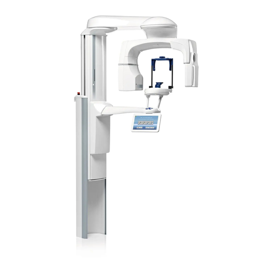
6 Main parts 6 Main parts 6.1 General view of X-ray system 1 X-ray unit 2 3D reconstruction PC 3 Planmeca Romexis program 4 ProTouch desktop application (optional, see section "ProTouch desktop application" on page 18) 5 Ethernet switch User's manual... -
Page 14: General View Of X-Ray Unit
Patient positioning controls (see section "Patient positioning controls" on page 19) Touch screen (see section "Touch screen" on page 14) Telescopic column 10 Stationary column 11 Emergency stop button (see section "Emergency stop button" on page 14) Planmeca ProMax User's manual... -
Page 15: Sensor
6 Main parts 6.3 Sensor 1 3D sensor for Planmeca ProMax 3D Plus and Planmeca ProMax 3D Mid 2 ProFace sensor for Planmeca ProMax 3D Plus and Planmeca ProMax 3D Mid 6.4 Tube head 1 Non-rotating tube head 2 Rotating tube head... -
Page 16: Patient Supports
6.5 Patient supports 6.5.1 Head supports (option A or B) Option A 1 Adjustable head support 2 Temple pads for children 3 Fastening straps 4 Support bars Option B 1 Head band 25 2 Support bars Planmeca ProMax User's manual... -
Page 17: Chin Supports
X-ray system is ready for an exposure. During exposure yellow radiation warning lights illuminate on the exposure switch and on the touch screen. They indicate that the X-ray unit is generating radiation. 1 Exposure switch 2 Exposure button User's manual Planmeca ProMax... -
Page 18: Emergency Stop Button
The actual exposure area depends on the individual anatomy of the patient. NOTE Never allow patients to touch the screen when they are positioned in the X- ray unit. Touching the screen during exposure will stop the imaging process. Planmeca ProMax User's manual... - Page 19 You hear an audible signal when you make a selection. If you wish to adjust the volume of the signal, select Settings > User > 1300 Operational Settings > 1320 Audio Settings > Touch Volume. NOTE Do not use sharp objects to operate the touch screen. User's manual Planmeca ProMax...
- Page 20 Moving backward To go back to a previous screen, select a previous symbol at the bottom of the screen. Scrolling lists To scroll a list down or up, slide your finger on the touch screen. Planmeca ProMax User's manual...
- Page 21 The patient’s name and ID number are shown in the top right corner of the touch screen. The patient and exposure mode have to be selected in Planmeca Romexis. Checking DAP and CTDI values The estimated values for DAP (Dose Area Product) and CTDI (Computed Tomography Dose Index) display in black text on the touch screen before you take an exposure.
-
Page 22: Protouch Desktop Application
The application automatically closes when you accept the help message. You can reopen the application by double-clicking the icon again. The small icon in the bottom left corner of the screen indicates when the application is connected to the X-ray unit. Planmeca ProMax User's manual... -
Page 23: Patient Positioning Controls
X-ray unit. NOTE Pressing any of the positioning controls (button or joystick) switches the patient positioning lights on. The lights automatically switch off after two minutes. To switch them off earlier, press the positioning joystick. User's manual Planmeca ProMax... -
Page 24: X-Ray Unit Up / Down
Clear any obstruction before moving the column again. NOTE When positioning seated patients (for example, in a wheelchair) always first move the X-ray unit down before you position the patient in the unit. Planmeca ProMax User's manual... -
Page 25: Positioning Joystick
6.10.4 Open / close temple supports Press the temple support button to open the temple supports in 2D imaging. Close the temple supports by pressing the temple support button again. User's manual Planmeca ProMax... -
Page 26: Planmeca Promax 3D Plus And 3D Mid Programs
7 Planmeca ProMax 3D Plus and 3D Mid programs 7 Planmeca ProMax 3D Plus and 3D Mid programs 7.1 3D Dental NOTE The values in parentheses represent the child size volumes. Program Planmeca ProMax 3D Plus Planmeca ProMax 3D Mid Tooth Ø40 x H50 mm (Ø34 x H42 mm) -
Page 27: Special Programs
7 Planmeca ProMax 3D Plus and 3D Mid programs Program Planmeca ProMax 3D Plus Planmeca ProMax 3D Mid Temporal bone Ø80 x H80 mm (Ø68 x H68 mm) Ø80 x H80 mm (Ø68 x H68 mm) Vertebrae Ø80 x H80 mm (Ø68 x H68 mm) Ø80 x H80 mm (Ø68 x H68 mm) -
Page 28: Patient Exposure
8.1 Preparing X-ray system 8.1.1 Attaching and removing sensor CAUTION Do not drop the sensor. Planmeca limited warranty does not cover damage which is due to misuse, e.g. dropping the sensor, neglect, or any cause other than ordinary use. If you have any reason to believe that the sensor might be faulty, take a test exposure before taking a patient exposure. - Page 29 3. Push in the C-arm electrical connector button on the other side. This will make the electrical connection between the sensor and C-arm. 8.1.1.2 Detaching sensor from C-arm NOTE Do not remove the sensor during imaging process. User's manual Planmeca ProMax...
- Page 30 8 3D patient exposure 1. Push in the C-arm electrical connector. This will disconnect the electrical connection between the sensor and C-arm. 2. Turn the locking knob 180 degrees. This will release the locking mechanism. Planmeca ProMax User's manual...
-
Page 31: Attaching Patient Supports
The available head supports are shown in section "Head supports (option A or B)" on page 12. 8.1.2.1 Attaching support bars Insert the support bars into the holes in the patient support table and secure them in position by tightening the locking knobs. User's manual Planmeca ProMax... - Page 32 8.1.2.2 Head support A: Attaching adjustable head support If you are using the adjustable head support, slide it onto the support bars. Then turn the adjusting knob to adjust the head support to suit the size of the patient’s head. Planmeca ProMax User's manual...
- Page 33 Do not overstretch the straps. The straps lose their elasticity if you pull them more than 50 mm (2 in.). Straps with a free length (i.e. when they are not stretched) of over 255 mm (10 in.) do not support the patient’s head firmly. User's manual Planmeca ProMax...
- Page 34 8.1.2.4 Attaching chin cup Use these patient supports. NOTE FOR ORTHODONTISTS: Use these patient supports if you wish to see the hyoid bone and neck bones better. Planmeca ProMax User's manual...
-
Page 35: Preparing Planmeca Romexis
8 3D patient exposure 8.1.3 Preparing Planmeca Romexis First select the patient. Then select the 3D exposure. Refer to the Planmeca Romexis User’s Manual for details on Romexis functions. 8.2 Preparing patient Ask the patient to remove any spectacles, hearing aids, dentures, hairpins, and personal jewellery such as earrings, necklaces and piercings as these can produce shadows or reflections in the image. -
Page 36: Selecting Program
Select the 3D program you wish to use. For more information on the available programs, see section "Planmeca ProMax 3D Plus and 3D Mid programs" on page 22. 8.3.2 Selecting patient size Use this button to select the patient size: •... -
Page 37: Selecting Volume Diameter
Use this button to select the diameter of the image volume. NOTE The available options depend on the selected program. For more information on Planmeca 3D Plus and 3D Mid programs, see section "Planmeca ProMax 3D Plus and 3D Mid programs" on page 22. 8.3.4 Selecting volume height Use this button to select the height of the image volume (full, lower or upper height). -
Page 38: Selecting Volume Position
NOTE The available options depend on the selected program and image resolution. 8.4 Patient positioning 8.4.1 Selecting patient entry position Use the buttons on the right of the screen to select the patient entry position. Planmeca ProMax User's manual... -
Page 39: Positioning Patient's Head
You can adjust the head support by turning the adjusting knob at the top. • You can use fastening straps for additional head support if needed. Refer to section "Attaching patient supports" on page 27 for details. 8.5 Selecting exposure values To go to the next screen, select: User's manual Planmeca ProMax... -
Page 40: Selecting Image Resolution
NOTE The available options depend on the selected program and X-ray unit model. NOTE The exposure values will automatically change according to the selected patient size, image resolution and ULD setting. Planmeca ProMax User's manual... -
Page 41: Selecting Ultra Low Dose (Uld)
Factory presets for image resolution Low dose in programs Nose and Sinus Patient size kV value mA value mA value with X-ray units with 90 kV X-ray tube User's manual Planmeca ProMax... - Page 42 X-ray units with 90 kV X-ray tube Child (XS) Small adult (S) Medium-sized adult (M) Large adult (L) Extra large adult (XL) X-ray units with 120 kV X-ray tube (D-059SBR & SXR 130-10-0.5 SC) Planmeca ProMax User's manual...
- Page 43 X-ray units with 90 kV X-ray tube Child (XS) Small adult (S) Medium-sized adult (M) Large adult (L) 12.5 Extra large adult (XL) X-ray units with 120 kV X-ray tube (D-059SBR) User's manual Planmeca ProMax...
- Page 44 2. Use the minus or plus buttons to set the exposure values you wish to use. To improve the image contrast, reduce the kV value. To reduce the radiation dose, reduce the mA value. 3. Select the green check mark button. Planmeca ProMax User's manual...
-
Page 45: Selecting Patient Movement Correction
NOTE The Planmeca CALM algorithm is for use only on live patients and is not recommended for use, for example, in imaging involving an inorganic sample or QA phantom attachment. -
Page 46: Adjusting Volume Position
If this is not the case, adjust the volume position according to the patient’s anatomy. The positioning lights and the illustrations on the touch screen help you to do this. Planmeca ProMax User's manual... -
Page 47: Moving Image Volume Vertically (Z Laser)
The lights automatically switch off after two minutes. To switch them off earlier, press the positioning joystick. 8.8.1 Moving image volume vertically (Z laser) The volume bottom light (Z laser) indicates the position where the lower edge of the image volume is. User's manual Planmeca ProMax... -
Page 48: Moving Image Volume Horizontally (X And Y Lasers)
Check that the image volume is positioned correctly for your patient. If you need to adjust the volume position, proceed as follows. 8.8.2.1 Front light (X laser) If you need to move the image volume to your left or right: Planmeca ProMax User's manual... - Page 49 NOTE Image volumes with large diameters (3D Plus: Ø > 70 mm / 3D Mid: Ø > 80 mm) are slightly offset towards the column. These image volumes cannot be moved to the left or right. User's manual Planmeca ProMax...
- Page 50 The side light (Y laser, i.e. the image volume centre as seen from the side) will move accordingly on your patient’s face. NOTE The largest image volume (3D Plus: Ø160 mm / 3D Mid: Ø200 mm) cannot be moved. Planmeca ProMax User's manual...
-
Page 51: Taking A Scout Image Or 2D Views (Lat, Pa Or Lat-Pa)
If the image consists of several volumes, scout imaging is available for the first image volume (1/2) only. NOTE 2D views are not available for all programs. NOTE Make sure that you have selected the correct patient and exposure mode in the Planmeca Romexis program. User's manual Planmeca ProMax... - Page 52 5. Press and hold down the exposure button for the entire duration of the exposure. During exposure yellow radiation warning lights illuminate on the exposure switch and on the touch screen, and you hear a radiation warning tone. Additionally, a radiation warning symbol is shown on the touch screen. Planmeca ProMax User's manual...
-
Page 53: Taking A 3D Exposure
Tooth and Teeth programs. 8.10 Taking a 3D exposure NOTE Make sure that you have selected the correct patient and exposure mode in the Planmeca Romexis program. 1. Make sure that the Volume tab is selected. User's manual Planmeca ProMax... - Page 54 Additionally, a radiation warning symbol displays on the touch screen. The C-arm moves around the patient’s head. • Planmeca ProMax 3D Mid X-ray units: If you take two vertical image volumes, the lower volume is imaged first and the upper volume last. The C-arm is automatically moved upwards between the volumes.
- Page 55 You hear a fast ticking sound when the photo is taken. • Planmeca ProMax 3D Mid X-ray units: If you take two vertical image volumes and a 3D face photo, the photo is taken between the X-ray images. You hear a fast ticking sound when the photo is taken and a warning tone when the C- arm moves up.
-
Page 56: Face Photo
To get a realistic image of the patient's face, do not use the chin cup or the fastening straps when taking 3D face photos. Select the patient and the 3D exposure as described in section "Preparing Planmeca Romexis" on page 31. Planmeca ProMax User's manual... -
Page 57: Patient Positioning
5. Position the patient’s head in the head support. You can adjust the head support by turning the adjusting knob at the top. User's manual Planmeca ProMax... -
Page 58: Selecting Exposure Settings
9.3 Selecting exposure settings 1. To go to the next screen, select: • This symbol • The forward button 2. Use this button to select the type of photo you wish to take. You can toggle between two options: Planmeca ProMax User's manual... - Page 59 4. Check that the side light (Y laser) is positioned 1 - 3 cm (0.4 - 1.2 in.) behind the patient’s eye corner. • If you need to adjust the side light, move the positioning joystick towards you (laser to the front) or away from you (laser to the back). User's manual Planmeca ProMax...
-
Page 60: Taking A 3D Face Photo
3. Press and hold down the exposure button for the entire duration of the exposure. You hear a fast ticking sound when the photo is taken. Planmeca ProMax User's manual... - Page 61 9 3D face photo 4. The photo is shown on the computer screen. 5. Release the patient from the head support by turning the adjusting knob at the top. 6. Guide the patient away from the X-ray unit. User's manual Planmeca ProMax...
-
Page 62: Model Exposure
If the plaster cast consists of two materials, the X-ray unit has to be calibrated for the teeth material. 10.1.1 Preparing calibration material 1. Insert impression material (1) into the calibration cup (2) provided (part number 10031325), until the calibration cup is full. Planmeca ProMax User's manual... - Page 63 4. Remove all excess material from the top of the calibration cup. 5. Gently pull the calibration pin out and ensure that the surfaces of the hole formed by the calibration pin are even (no air bubbles in inside walls). User's manual Planmeca ProMax...
-
Page 64: Selecting Settings
1. On the X-ray unit, select the program. • For impression material select 3D Models > Impression • For plaster material select 3D Models > Plaster Cast 2. To go to the next screen, select: • This symbol • The forward button Planmeca ProMax User's manual... - Page 65 You can use either image resolution (Fast or High resolution) for the calibration process. 4. Place the calibration cup on the polystyrene disc so that the volume centre lights cross in the middle of the cup. User's manual Planmeca ProMax...
- Page 66 10 3D model exposure 5. In the Planmeca Romexis program, select the patient. 6. Select 3D Imaging > Model Capture. 7. Select the option Add Material in the window that displays. Planmeca ProMax User's manual...
-
Page 67: Taking A Calibration Exposure
3. Press and hold down the exposure button for the entire duration of the exposure. During exposure yellow radiation warning lights illuminate on the exposure switch and on the touch screen, and you hear a radiation warning tone. Additionally, a radiation warning symbol is shown on the touch screen. User's manual Planmeca ProMax... -
Page 68: Taking An Exposure Of An Impression Or Plaster Cast
10 3D model exposure 4. In the Planmeca Romexis program, enter a name for this material and select OK. NOTE The calibration exposure values are automatically included at the beginning of the name. 10.2 Taking an exposure of an impression or plaster cast NOTE The X-ray unit has to be calibrated for each new material that is used. - Page 69 3. To go to the next screen, select: • This symbol • The forward button The positioning lights (volume center lights and volume bottom light) come on. The volume center lights cross in the middle of the image volume. User's manual Planmeca ProMax...
- Page 70 5. Select the exposure values that you used in the calibration process for this material. Refer to section "Adjusting exposure values for current exposure" on page 37 if you need to adjust the preset exposure values. Planmeca ProMax User's manual...
- Page 71 Move the C-arm up about 13 mm (0.5 in.) by pressing the image volume up button. 1 Volume centre lights 2 Impression on polystyrene disc 7. If not done yet, in the Planmeca Romexis program, select the patient. User's manual Planmeca ProMax...
-
Page 72: Taking An Exposure
Green lights flash on the touch screen and exposure button when the X- ray system is getting ready for an exposure. The green lights stop flashing and stay on continuously when the X-ray system is ready for an exposure. 2. Move to a protected area. Planmeca ProMax User's manual... - Page 73 Additionally, a radiation warning symbol is shown on the touch screen. 4. The image is shown on the computer screen. NOTE The Romexis function Model Capture creates surface models (instead of voxel data images). User's manual Planmeca ProMax...
-
Page 74: Settings
Settings that can be entered by the user: • User • Program • About Settings that can be entered by service personnel only (password required): • Technical To return to the main screen, select the settings symbol at the top left corner. Planmeca ProMax User's manual... -
Page 75: User Settings
1. Select User > 1200 Time and Date > 1210 Set System Time and Time / Date Display Format > Time Display Format. 2. Select the display format you wish to use. 3. Select the green check mark button. User's manual Planmeca ProMax... - Page 76 2. Use the plus and minus buttons to change the time. 3. Select the green check mark button. NOTE The time is set to the local time at the factory. Change the time setting to show the correct time before you start using the X-ray unit. Planmeca ProMax User's manual...
-
Page 77: Operational Settings (1300)
1. Select User > 1300 Operational Settings > 1310 Use Mode. 2. Select the mode you wish to use. In demo mode you can practice or demonstrate the functions of the X- ray unit without radiation and PC connection. 3. Select the green check mark button. User's manual Planmeca ProMax... - Page 78 Turn this option OFF if you do not wish to use the open (full view) patient entry position. This might be necessary if there is no space for the C-arm to move back. • Midsagittal and Frankfort Lights in Tomo Planmeca ProMax User's manual...
- Page 79 Note that the setting affects all indicator lights that are connected to your X-ray system (indicator light on the hand-held exposure switch, wall exposure switch(es) and remote exposure lamp). 3. Select the green check mark button. User's manual Planmeca ProMax...
-
Page 80: Network Settings (1400)
4. Move to a protected area. 5. Press and hold down the exposure button for the duration of the exposure. The C-arm will not move when you take a test exposure. 6. Select the green check mark button. Planmeca ProMax User's manual... -
Page 81: Clinic Management (1600)
• To view network settings for Clinic Management: Select User > 1600 Clinic Management to view the network settings for the Planmeca Romexis Clinic Management module. NOTE Only a service technician or local administrator may change the settings. 11.2 Program settings 11.2.1 Programs (2100) - Page 82 (i.e. overrule your own settings) by selecting Program > 2500 Reset to Factory Defaults. NOTE You can adjust the preset exposure values temporarily as described in section "Adjusting exposure values for current exposure" on page 37. Planmeca ProMax User's manual...
-
Page 83: Program Features (2200)
• Vertical Extension (For Planmeca ProMax 3D Plus only) • 4D Jaw Motion (4D Jaw Motion program for Planmeca ProMax 3D Mid X-ray units with ProFace sensor) • ProTouch Desktop (Virtual control panel that allows you to take exposures) -
Page 84: Reset To Factory Defaults (2500)
The preset exposure values for 3D patient exposures are shown in section "Adjusting exposure values for current exposure" on page 37 and for 3D model exposures in section "Selecting settings" on page 60. 2. Select the green check mark button. Planmeca ProMax User's manual... -
Page 85: About Tab
QR code reader installed on your mobile device (e.g. smartphone), hold the device steady over the QR code. You will be directed to Planmeca's product registration page. 2. Go to Planmeca's product registration page at www.planmeca.com/ register. User's manual Planmeca ProMax... - Page 86 3. Select the green check mark button. 4. Follow the instructions on the registration page. Note that when you enter the X-ray unit serial number, you have to include any letters shown at the beginning of the number. Planmeca ProMax User's manual...
-
Page 87: Help Messages
Check the scan and layer detected. settings. H142 Height movement Height movement is not possible Clear any obstruction before because one (or more) of the moving the column again. positioning control buttons or the positioning joystick is stuck. User's manual Planmeca ProMax... - Page 88 H175 PC program selection is in conflict Select another exposure with the selected X-ray unit program. mode in Planmeca Romexis. H180 DEC is not available. H181 The imaging process was cancelled in Planmeca Romexis.
- Page 89 Restart reconstruction PC or Reconstruction PC. contact technical support if problem persists. H199 The 3D reconstruction PC does not Upgrade the 3D support the CALM algorithm reconstruction PC or deactivate the CALM licence. Contact your service technician for help. User's manual Planmeca ProMax...
-
Page 90: Error Messages
The X-ray unit will not accept any commands from the user until the error message is cleared from the touch screen. Guide the patient away from the X-ray unit. Then clear the message by touching the green check mark. Planmeca ProMax User's manual... -
Page 91: Cleaning And Disinfection
NOTE Switch the X-ray unit off before cleaning and disinfection. NOTE Use a Planmeca approved cleaning agent and surface disinfectant. The products are categorised here as cleaning agents and / or disinfectants according to the information provided by the manufacturers. -
Page 92: Patient Supports, Patient Handles And Touch Screen
14 Cleaning and disinfection 14.1 Patient supports, patient handles and touch screen Wipe these parts after each patient using a Planmeca approved surface disinfectant. Use a Planmeca approved cleaning agent for cleaning stains and dirt if needed. 3D patient supports Panoramic patient supports... - Page 93 14 Cleaning and disinfection Cephalometric patient supports Patient handles and touch screen User's manual Planmeca ProMax...
- Page 94 14 Cleaning and disinfection NOTE FOR HEAD BAND 25: Wipe the head band after each patient using a mild cleaning agent and a clean soft cloth. Do not use disinfectants. Planmeca ProMax User's manual...
-
Page 95: Other Surfaces
14 Cleaning and disinfection 14.2 Other surfaces Wipe the other surfaces regularly using a Planmeca approved surface disinfectant. Use a Planmeca approved cleaning agent for cleaning stains and dirt if needed. User's manual Planmeca ProMax... - Page 96 14 Cleaning and disinfection NOTE FOR PROFACE SENSOR: Clean the laser windows regularly using compressed air. NOTE The parts in the figure below can be autoclaved at 134°C (273°F). The parts can be autoclaved up to 100 times. Planmeca ProMax User's manual...
-
Page 97: Service
15 Service 15 Service The X-ray unit must be checked by a qualified Planmeca service technician once a year or after every 10 000 exposures (if this is sooner). This will guarantee patient and user safety and ensure consistent image quality. -
Page 98: Disposal
16 Disposal 16 Disposal In order to reduce the environmental load over the product’s entire lifecycle, Planmeca products are designed to be as safe as possible to dispose of. Planmeca products fulfil the requirements of Directives 2011/65/EU (RoHS) and 2012/19/EU (WEEE). -
Page 99: Technical Data For Planmeca Promax Product Family
17 Technical data for Planmeca ProMax product family 17 Technical data for Planmeca ProMax product family Classification Medical Device Directive 93/42/EEC (Class IIb) RoHS 2011/65/EU IEC 60601-1 Class I, type B CISPR 11 Class B IP Classification IP20 Applied parts (according to IEC 60601-1: 2012) - Page 100 17 Technical data for Planmeca ProMax product family Ceph 1 - 16 mA ±10% 3D s / 3D Classic / 3D Plus / 3D Mid with X-ray tube D-054SB or 3D Max with X-ray tube D-067SB 3D: 1 - 14 mA ±10% Pan / SmartPan: 1 - 16 mA ±10%...
- Page 101 17 Technical data for Planmeca ProMax product family 3D / SmartPan • 3D s / 3D Classic: 528 mm (20.7 in.) • 3D Plus or 3D Mid with X-ray tube D-054SB / 3D Max with X-ray tube D-067SB: 600 mm (23.6 in.)
- Page 102 17 Technical data for Planmeca ProMax product family 3D Max 139 kg (306 lb) Scanning ceph 26 kg (57 lb) Planmeca ProCeph 20 kg (44 lb) Environmental requirements Transport: Temperature -20°C - +60°C (-4°F - +140°F) Relative humidity 10 - 90% RH (non-condensing)
- Page 103 17 Technical data for Planmeca ProMax product family Operating conditions for X-ray units with ProFace sensor Optimum colour temperature Approx. 6500 Kelvin Frequency for fluorescent lamps 100 Hz Even and uniform lighting No natural light Original manufacturer Planmeca Oy, Asentajankatu 6, FIN-00880, Helsinki, Finland Phone: +358 20 7795 500, Fax: +358 20 7795 555, www.planmeca.com...
- Page 106 Planmeca Oy | Asentajankatu 6 | 00880 Helsinki | Finland tel. +358 20 7795 500 | fax +358 20 7795 555 | sales@planmeca.com | www.planmeca.com...
Need help?
Do you have a question about the ProMax 3D Plus and is the answer not in the manual?
Questions and answers