Planmeca Promax 3D s User Manual
Hide thumbs
Also See for Promax 3D s:
- User manual (102 pages) ,
- Technical manual (378 pages) ,
- User manual (102 pages)
Table of Contents
Advertisement
Advertisement
Table of Contents

Subscribe to Our Youtube Channel
Related Manuals for Planmeca Promax 3D s


Summary of Contents for Planmeca Promax 3D s
- Page 1 Planmeca ProMax & Planmeca ProMax 3D s / 3D user's manual 2D imaging...
-
Page 3: Table Of Contents
13.1 Double TMJ exposure (lateral, PA or lateral-PA) ............69 13.2 Multi-angle TMJ exposure (PA or lateral) ..............75 SINUS EXPOSURE ..................80 14.1 Patient positioning ......................81 14.2 Taking an exposure ..................... 83 Planmeca ProMax & Planmeca ProMax 3D s / 3D 1 User’s Manual (2D) - Page 4 IEC 60364 - equipment is used according to the operating instructions Planmeca pursues a policy of continual product development. Although every effort is made to produce up-to-date product documentation this publication should not be regarded as an infallible guide to current specifications. We reserve the right to make changes without prior notice.
-
Page 5: Introduction
The radiation dose can be reduced by decreasing the suggested mA value. The display values shown in this manual are only examples and should not be interpreted as recommended values unless otherwise stated. Planmeca ProMax & Planmeca ProMax 3D s / 3D 1 User’s Manual (2D) -
Page 6: Associated Documentation
• User’s Manual, Original English publication: 10014593 • Installation Manual, Original English publication: 10014600 NOTE The latest versions of the User’s Manuals are available on Planmeca’s website. 2 Planmeca ProMax & Planmeca ProMax 3D s / 3D User’s Manual (2D) -
Page 7: Symbols On Product Labels
Type B applied part (Standard IEC 60601-1) Separate collection for electrical and electronic equipment (Directive 2002/96/EC WEEE) Alternating current (Standard IEC 60417) Electrostatic sensitive device (Standard IEC 60417) Planmeca ProMax & Planmeca ProMax 3D s / 3D 3 User’s Manual (2D) -
Page 8: Safety Precautions
NOTE When it is likely that evaluation of soft tissues will be required part patient’s radiological assessment, conventional CT or MR medical imaging should be used rather than CBCT. 4 Planmeca ProMax & Planmeca ProMax 3D s / 3D User’s Manual (2D) - Page 9 Planmeca Romexis program. The last ten images can be manually imported into Romexis. NOTE Never place or hang any objects on any part of the X- ray unit. Planmeca ProMax & Planmeca ProMax 3D s / 3D 5 User’s Manual (2D)
-
Page 10: Switching X-Ray Unit On
The X-ray unit is then ready for use. On / off switch NOTE To prolong the lifetime of the X-ray unit, always switch the unit off when it is not in active use. 6 Planmeca ProMax & Planmeca ProMax 3D s / 3D User’s Manual (2D) -
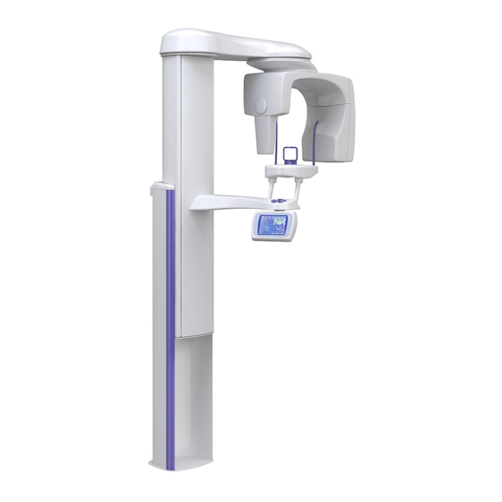
Page 11: Main Parts
MAIN PARTS MAIN PARTS General view of 2D X-ray system Ethernet 1 X-ray unit 2 Planmeca Romexis program Planmeca ProMax & Planmeca ProMax 3D s / 3D 7 User’s Manual (2D) -
Page 12: General View Of 3D X-Ray System
MAIN PARTS General view of 3D X-ray system Ethernet 1 X-ray unit 2 3D reconstruction PC 3 Planmeca Romexis program 8 Planmeca ProMax & Planmeca ProMax 3D s / 3D User’s Manual (2D) -
Page 13: General View Of X-Ray Unit
MAIN PARTS General view of X-ray unit C-arm Cephalostat (optional) Sensor Patient support Patient support table Patient handles Patient positioning controls Control panel Telescopic column Stationary column Planmeca ProMax & Planmeca ProMax 3D s / 3D 9 User’s Manual (2D) -
Page 14: Sensors
Sensors Dimax sensor 3D sensor for 3D sensor for Planmeca ProMax 3D s Planmeca ProMax 3D ProFace sensor for Planmeca ProMax 3D s and Planmeca ProMax 3D 10 Planmeca ProMax & Planmeca ProMax 3D s / 3D User’s Manual (2D) -
Page 15: Patient Supports
MAIN PARTS Patient supports Bite piece Temple supports Chin rest Chin cup Chin support Adapter Planmeca ProMax & Planmeca ProMax 3D s / 3D 11 User’s Manual (2D) -
Page 16: Exposure Switch
C-arm will stop moving and a help message will appear on the control panel display. Guide the patient away from the X-ray unit. Then clear the help message by touching OK. 12 Planmeca ProMax & Planmeca ProMax 3D s / 3D User’s Manual (2D) -
Page 17: Emergency Stop Button
A help message will appear on the control panel display. Guide the patient away from the X-ray unit. Then release the emergency stop button. The X-ray unit will automatically restart. Planmeca ProMax & Planmeca ProMax 3D s / 3D 13 User’s Manual (2D) -
Page 18: Programs
SCARA 2 or Dimax (optional) SCARA 3 SCARA 3 Planmeca ProCeph ProCeph Dynamic Exposure Panoramic DEC SCARA 2 or Dimax Control (DEC) SCARA 3 Cephalometric DEC (optional) 14 Planmeca ProMax & Planmeca ProMax 3D s / 3D User’s Manual (2D) - Page 19 (+ Face Scan) 3D Horizontal Pair (+ Face Scan) Face Scan 3D Model 3D Impression scan SCARA 3 3D or (optional) 3D ProFace 3D Plaster cast scan Planmeca ProMax & Planmeca ProMax 3D s / 3D 15 User’s Manual (2D)
-
Page 20: Panoramic Programs
1 cm NOTE This program is optimized for interproximal imaging and a shadow of the opposite side teeth may therefore be visible in the radiograph. 16 Planmeca ProMax & Planmeca ProMax 3D s / 3D User’s Manual (2D) -
Page 21: Temporomandibular Joint (Tmj) Programs
Lateral TMJ exposures of closed (1/2) and open (2/2) temporomandibular joints. SCARA 3 units SCARA 3 units: The imaging position and angle can be adjusted. The default imaging angle is 17°. 1 cm Planmeca ProMax & Planmeca ProMax 3D s / 3D 17 User’s Manual (2D) - Page 22 SCARA 2 units SCARA 2 units: The imaging geometry is different. It is not possible to adjust the imaging position or angle. 1 cm 18 Planmeca ProMax & Planmeca ProMax 3D s / 3D User’s Manual (2D)
- Page 23 The imaging angle for image no. 2 is adjustable (three imaging angles: 17° ±7° by default). The selected imaging angle is in image no. 2. 1 cm Planmeca ProMax & Planmeca ProMax 3D s / 3D 19 User’s Manual (2D)
-
Page 24: Sinus Programs
X-ray X-ray beam. 1 cm Lateral non-rotational (L / R) Lateral non-rotational exposure of the left or right sinus area. X-ray (L) 1 cm 20 Planmeca ProMax & Planmeca ProMax 3D s / 3D User’s Manual (2D) -
Page 25: Tomography / Transtomography Programs
NOTE Vertical artefacts caused by high contrast objects may be visible in transtomography when a layer thickness of 1mm is used. Select a thicker layer to avoid this. Planmeca ProMax & Planmeca ProMax 3D s / 3D 21 User’s Manual (2D) - Page 26 The angle of the first exposure is the selected angle +7° counterclockwise, and the angle of the third exposure is the selected angle +7° clockwise. 3xCRS_AutoAng .eps The selected target position is image no. 2. 22 Planmeca ProMax & Planmeca ProMax 3D s / 3D User’s Manual (2D)
- Page 27 The selected target position is image no. 2. SINUS PA Sinus & Nasal (Transtomography) 1 wide postero-anterior image from the sinus area / midsagittal plane (nasal cavity). Left SINUS Right NASAL Planmeca ProMax & Planmeca ProMax 3D s / 3D 23 User’s Manual (2D)
- Page 28 The angle of the first exposure is the selected angle +7° counterclockwise, and the angle of the third exposure is the selected angle +7° clockwise. The selected target position is image no. 2. 24 Planmeca ProMax & Planmeca ProMax 3D s / 3D User’s Manual (2D)
- Page 29 Left Right Lateral Sinus & Nasal (Transtomography) 1 wide longitudinal image from the sinus area / midsagittal plane (nasal cavity). SINUS Left SINUS Right NASAL Left Right Planmeca ProMax & Planmeca ProMax 3D s / 3D 25 User’s Manual (2D)
- Page 30 The angle of the first CRS exposure is the selected angle +7° counterclockwise, and the angle of the third CRS exposure is the selected angle +7° clockwise. The selected target position is image no. 2. 26 Planmeca ProMax & Planmeca ProMax 3D s / 3D User’s Manual (2D)
-
Page 31: Control Panel
NOTE The exposure time indicated on the display before an exposure is taken is an estimated value. The real value is shown after the exposure. Variation in exposure time is caused by mA automation. Planmeca ProMax & Planmeca ProMax 3D s / 3D 27 User’s Manual (2D) -
Page 32: General Settings
The preset exposure values are average values and they are only meant to guide the user. To change the preset exposure values, touch the kV / mA field on the main display. 28 Planmeca ProMax & Planmeca ProMax 3D s / 3D User’s Manual (2D) - Page 33 NOTE If needed, the Go Entry 1 function can be disabled as described in section “Behavioural preferences (i230)” on page 45. This might be necessary if there is no space for the C-arm to move back. Planmeca ProMax & Planmeca ProMax 3D s / 3D 29 User’s Manual (2D)
-
Page 34: Selecting Panoramic Program
Refer to section 7.1 “Panoramic programs” on page 16 for a more detailed description of the program types. When you have selected the program the main display will be shown again. 30 Planmeca ProMax & Planmeca ProMax 3D s / 3D User’s Manual (2D) - Page 35 NOTE Selecting jaw shape and size manually will override the automatic setting. Jaw size: Narrow Average Wide Jaw shape: V-shaped Normal Square Confirm the selection and return to the main display by touching OK. Planmeca ProMax & Planmeca ProMax 3D s / 3D 31 User’s Manual (2D)
- Page 36 NOTE DEC and horizontal segmenting cannot be used simultaneously. NOTE If Autofocus is switched on (AF ON), DEC will be automatically switched off for the first exposure (scout image). 32 Planmeca ProMax & Planmeca ProMax 3D s / 3D User’s Manual (2D)
- Page 37 The setting can be adjusted between 20% (lower exposure values -> brighter image) and 200% (higher exposure values -> darker image). recommended setting is 100% (default setting). Planmeca ProMax & Planmeca ProMax 3D s / 3D 33 User’s Manual (2D)
- Page 38 The exposure will be taken in two stages and the C-arm will move twice. 34 Planmeca ProMax & Planmeca ProMax 3D s / 3D User’s Manual (2D)
-
Page 39: Selecting Temporomandibular Joint (Tmj) Program
Refer to section 7.2 “Temporomandibular joint (TMJ) programs” on page 17 for a more detailed description of the program types. When you have selected the program the main display will be shown again. Planmeca ProMax & Planmeca ProMax 3D s / 3D 35 User’s Manual (2D) - Page 40 NOTE You can set the X-ray unit so that the imaging position will be automatically moved forwards for the open jaw exposure, refer to section “Default program settings (i270)” on page 49. 36 Planmeca ProMax & Planmeca ProMax 3D s / 3D User’s Manual (2D)
- Page 41 Touching the arrow of a deselected side again will change the color back to white. Confirm the selection and return to the main display by touching OK. Planmeca ProMax & Planmeca ProMax 3D s / 3D 37 User’s Manual (2D)
-
Page 42: Selecting Sinus Program
Refer to section 7.3 “Sinus programs” on page 20 for a more detailed description of the program types. When you have selected the program the main display will be shown again. 38 Planmeca ProMax & Planmeca ProMax 3D s / 3D User’s Manual (2D) -
Page 43: Selecting Tomography / Transtomography Program
On the next displays, select the program you wish to use. Refer to section 7.4 “Tomography / transtomography programs” on page 21 for a more detailed description of the program types. Planmeca ProMax & Planmeca ProMax 3D s / 3D 39 User’s Manual (2D) - Page 44 (full collimation) exposure by touching the Size field. If you select Lower or Upper only the selected jaw will be exposed, and selecting Full will produce a full size exposure of both jaws. 40 Planmeca ProMax & Planmeca ProMax 3D s / 3D User’s Manual (2D)
- Page 45 NOTE The position of the target area is based on average jaw measurements. The position must be adjusted after the patient has been positioned in the unit, see section 15.2 “Adjusting position of target area” on page 88. Planmeca ProMax & Planmeca ProMax 3D s / 3D 41 User’s Manual (2D)
-
Page 46: Information Displays
To get to the list of the Information displays, first touch the i field. The display shown below appears. You can return to the main display by touching the Exit field. 42 Planmeca ProMax & Planmeca ProMax 3D s / 3D User’s Manual (2D) -
Page 47: User Preference Settings (I200)
(i210). If you want to change the date, select Set date. The option Date & time display format allows you to select the format you wish to use for displaying date and time. Planmeca ProMax & Planmeca ProMax 3D s / 3D 43 User’s Manual (2D) - Page 48 The selected options will be marked with a blue dot. Confirm your selections by touching Done or exit the display without saving changes by touching the Cancel field. 44 Planmeca ProMax & Planmeca ProMax 3D s / 3D User’s Manual (2D)
- Page 49 Save the new setting by touching the Done field or exit the display without saving changes by touching the Cancel field. Behavioural preferences (i230) Select Behavioural preferences (i230) on the User preference settings (i200) display. Planmeca ProMax & Planmeca ProMax 3D s / 3D 45 User’s Manual (2D)
- Page 50 To deselect a function, touch the field again. The green check mark will disappear. Confirm your selection(s) by touching Done. Touching the Cancel field will bring you back to the User preference settings (i200) display. 46 Planmeca ProMax & Planmeca ProMax 3D s / 3D User’s Manual (2D)
- Page 51 Return to the original size by touching Overview. Accept the preview image by touching OK. NOTE: This setting applies only to 2D exposures with Dimax sensor. Planmeca ProMax & Planmeca ProMax 3D s / 3D 47 User’s Manual (2D)
- Page 52 The selected language will be marked with a blue dot. Confirm your selection by touching Done. Touching the Cancel field will bring you back to the User preference settings (i200) display. 48 Planmeca ProMax & Planmeca ProMax 3D s / 3D User’s Manual (2D)
- Page 53 - ISO-FDI: TMJ-Right, 18 - 11, 48 - 41, 0, 21 - 28, 31 - 38, TMJ-Left The selected option will be marked with a dot. Touch Done to confirm your selection. Planmeca ProMax & Planmeca ProMax 3D s / 3D 49 User’s Manual (2D)
-
Page 54: Feature Program Control (I300)
Information displays. On this display new features can be added to the X-ray unit. To add new features, first select the option Enable / disable features (i310). A list of features will appear. 50 Planmeca ProMax & Planmeca ProMax 3D s / 3D User’s Manual (2D) - Page 55 X-ray unit and for the specified program feature. To disable the selected feature repeat the procedure. NOTE After enabling / disabling a new feature the X-ray unit must be restarted. Planmeca ProMax & Planmeca ProMax 3D s / 3D 51 User’s Manual (2D)
-
Page 56: Special Functions (I400)
“dummy run” function for training and demonstration purposes. For example, you might want to demonstrate the C-arm movements before taking exposures of children or nervous patients. 52 Planmeca ProMax & Planmeca ProMax 3D s / 3D User’s Manual (2D) - Page 57 X-ray unit, more detailed description). Error code and number of times the error has occurred Software version More detailed description Planmeca ProMax & Planmeca ProMax 3D s / 3D 53 User’s Manual (2D)
- Page 58 Touch the Start field. The word Ready appears at the bottom of the display and you can now press the exposure button to start the seasoning process. 54 Planmeca ProMax & Planmeca ProMax 3D s / 3D User’s Manual (2D)
- Page 59 Beam check (i470) Refer to the Technical Manual for more information on beam check. Network settings (i480) Refer to the Technical Manual for more information on network settings. Planmeca ProMax & Planmeca ProMax 3D s / 3D 55 User’s Manual (2D)
-
Page 60: Patient Positioning Controls
Open / close temple supports Press the temple support button to open the temple supports in 2D exposures. The temple supports can be closed by pressing the temple support button again. 56 Planmeca ProMax & Planmeca ProMax 3D s / 3D User’s Manual (2D) - Page 61 Positioning joystick The positioning joystick is used to adjust the position of the target area in tomographic or 3D exposures. The joystick can be moved in any direction. Planmeca ProMax & Planmeca ProMax 3D s / 3D 57 User’s Manual (2D)
-
Page 62: Preparations For Exposure
- use a 3D sensor to take 3D exposures and a Dimax sensor to take panoramic exposures. This option has selected information display i230 (Behavioural preferences -> Use Dimax sensor for panoramic). 58 Planmeca ProMax & Planmeca ProMax 3D s / 3D User’s Manual (2D) -
Page 63: Attaching And Removing Sensor
Push the sensor onto the connector on the C-arm. Sensor Turn the locking knob over the fastening mechanism. This Locking knob will secure the sensor in position. Planmeca ProMax & Planmeca ProMax 3D s / 3D 59 User’s Manual (2D) - Page 64 C-arm. C-arm electrical connector Sensor Locking The locking knob can now be turned 180 degrees. This knob will release the locking mechanism. Carefully pull the sensor out. 60 Planmeca ProMax & Planmeca ProMax 3D s / 3D User’s Manual (2D)
-
Page 65: Preparing Patient
NOTE High contrast objects, such as gold teeth or amalgam, may cause artefacts in the image. Place a protective lead apron over the patient’s back if required. Planmeca ProMax & Planmeca ProMax 3D s / 3D 61 User’s Manual (2D) -
Page 66: Panoramic Exposure
You can take a segment exposure by selecting only certain vertical or horizontal segments of the jaw, refer to section 8.3.2 “Selecting segmentation in panoramic programs” on page 32. 62 Planmeca ProMax & Planmeca ProMax 3D s / 3D User’s Manual (2D) -
Page 67: Patient Positioning
The incisal edges of the maxillary and mandibular teeth must be in the groove in the bite piece. Planmeca ProMax & Planmeca ProMax 3D s / 3D 63 User’s Manual (2D) - Page 68 Thumb wheel or by pressing any of the positioning controls (button or joystick). Positioning controls 64 Planmeca ProMax & Planmeca ProMax 3D s / 3D User’s Manual (2D)
- Page 69 Apices of upper central incisors Second Position the apices of the patient’s upper central incisors incisor Canine within the image layer of the unit. Layer light Planmeca ProMax & Planmeca ProMax 3D s / 3D 65 User’s Manual (2D)
-
Page 70: Taking An Exposure
The Romexis program will now show the Waiting for Exposure message on the computer screen. Green ready indicator light 66 Planmeca ProMax & Planmeca ProMax 3D s / 3D User’s Manual (2D) -
Page 71: Taking An Exposure With Autofocus (Scara 3 Units Only)
Take the first exposure as described in section 12.2 “Taking an exposure” on page 66. The first exposure is a short, low-dose exposure during which the optimal position for the image layer will be calculated. Planmeca ProMax & Planmeca ProMax 3D s / 3D 67 User’s Manual (2D) - Page 72 NOTE If the imaging process is cancelled from the Romexis program, Autofocus has to be switched off (AF OFF) and back on (AF ON) again before the next Autofocus exposure can be taken. 68 Planmeca ProMax & Planmeca ProMax 3D s / 3D User’s Manual (2D)
-
Page 73: Temporomandibular Joint (Tmj) Exposure
NOTE Always try to minimize the radiation dose to the patient. Exposure values for TMJ programs “Double lateral” and “Double lat-PA” PATIENT kV VALUE mA VALUE Child Adolescent Small adult Average-sized adult Large adult Planmeca ProMax & Planmeca ProMax 3D s / 3D 69 User’s Manual (2D) - Page 74 The patient's nose must rest on top of the support and their mouth must be closed, and their teeth must be together. 70 Planmeca ProMax & Planmeca ProMax 3D s / 3D User’s Manual (2D)
- Page 75 The Frankfort plane light, which is located on the side of the column, can be moved up or down. This is done by rotating the thumb wheel below the light slot. Frankfort plane light Planmeca ProMax & Planmeca ProMax 3D s / 3D 71 User’s Manual (2D)
- Page 76 NOTE Make sure that you have selected the right patient and the panoramic exposure mode in the Planmeca Romexis program before you take an exposure. Refer to the Romexis User’s Manual. 72 Planmeca ProMax & Planmeca ProMax 3D s / 3D User’s Manual (2D)
- Page 77 NOTE Maintain audio and visual contact with the patient and unit during exposure. If the C-arm stops moving during exposure, or moves in an erratic way, release the exposure button immediately. Planmeca ProMax & Planmeca ProMax 3D s / 3D 73 User’s Manual (2D)
- Page 78 Note that you must accept the image in the Planmeca Romexis program - only accepted images will be stored in the database. Refer to the Romexis User’s Manual. 74 Planmeca ProMax & Planmeca ProMax 3D s / 3D User’s Manual (2D)
-
Page 79: Multi-Angle Tmj Exposure (Pa Or Lateral)
Adolescent Small adult Average-sized adult Large adult Exposure values for multi-angle lateral TMJ programs PATIENT kV VALUE mA VALUE Child Adolescent Small adult Average-sized adult Large adult Planmeca ProMax & Planmeca ProMax 3D s / 3D 75 User’s Manual (2D) - Page 80 Positioning controls (button or joystick). controls 76 Planmeca ProMax & Planmeca ProMax 3D s / 3D User’s Manual (2D)
- Page 81 The Frankfort plane light, which is located on the side of plane the column, can be moved up or down. This is done by light rotating the thumb wheel that is below the light slot. Thumb wheel Planmeca ProMax & Planmeca ProMax 3D s / 3D 77 User’s Manual (2D)
- Page 82 NOTE Make sure that you have selected the right patient and the panoramic exposure mode in the Planmeca Romexis program before you take an exposure. Refer to the Romexis User’s Manual. 78 Planmeca ProMax & Planmeca ProMax 3D s / 3D User’s Manual (2D)
- Page 83 Note that you must accept the image in the Planmeca Romexis program - only accepted images will be stored in the database. Refer to the Romexis User’s Manual. Planmeca ProMax & Planmeca ProMax 3D s / 3D 79 User’s Manual (2D)
-
Page 84: Sinus Exposure
Average-sized adult Large adult Exposure values for sinus programs “Lateral non-rotational” and “Midsagittal non-rotational” PATIENT kV VALUE mA VALUE Child Adolescent Small adult Average-sized adult Large adult 80 Planmeca ProMax & Planmeca ProMax 3D s / 3D User’s Manual (2D) -
Page 85: Patient Positioning
Thumb wheel controls (button or joystick). Positioning controls Planmeca ProMax & Planmeca ProMax 3D s / 3D 81 User’s Manual (2D) - Page 86 NOTE Make sure that you have selected the right patient and the panoramic exposure mode in the Planmeca Romexis program before you take an exposure. Refer to the Romexis User’s Manual. 82 Planmeca ProMax & Planmeca ProMax 3D s / 3D User’s Manual (2D)
-
Page 87: Taking An Exposure
Note that you must accept the image in the Planmeca Romexis program - only accepted images will be stored in the database. Refer to the Romexis User’s Manual. Planmeca ProMax & Planmeca ProMax 3D s / 3D 83 User’s Manual (2D) -
Page 88: Tomographic Exposure
You can use lower exposure values when taking exposures at normal resolution. NOTE Always try to minimize the radiation dose to the patient. NOTE Refer corresponding cross-sectional/ longitudinal exposure values for combined exposure programs. 84 Planmeca ProMax & Planmeca ProMax 3D s / 3D User’s Manual (2D) - Page 89 Average-sized adult Large adult Exposure values for longitudinal transtomography programs 1-3 (Cuspid, 4-8 (Premolar/ Lat Sinus Midsagittal plane) Molar) PATIENT Child Adolescent Small adult Average-sized adult Large adult Planmeca ProMax & Planmeca ProMax 3D s / 3D 85 User’s Manual (2D)
-
Page 90: Patient Positioning
86 Planmeca ProMax & Planmeca ProMax 3D s / 3D User’s Manual (2D) - Page 91 Mandible exposure (position 4-8, premolar / molar) To take longitudinal or cross-sectional exposures of the mandible, position the lower edge of the mandible so that it is horizontal. Mandible.eps Planmeca ProMax & Planmeca ProMax 3D s / 3D 87 User’s Manual (2D)
-
Page 92: Adjusting Position Of Target Area
C-arm can be changed. NOTE If necessary, the midsagittal and Frankfort plane lights can be activated as described in section “Behavioural preferences (i230)” on page 45. 88 Planmeca ProMax & Planmeca ProMax 3D s / 3D User’s Manual (2D) - Page 93 Pressing the button on the left will rotate the C-arm clockwise, and pressing the button on the right will rotate the C-arm counterclockwise. The C-arm angle is shown on the main display. Planmeca ProMax & Planmeca ProMax 3D s / 3D 89 User’s Manual (2D)
-
Page 94: Patient Positioning With Impression Plate
88. Light A must be parallel to tangent of the jaw curve and light B must be perpendicular to the jaw. 90 Planmeca ProMax & Planmeca ProMax 3D s / 3D User’s Manual (2D) -
Page 95: Taking An Exposure
The Romexis program will now show the Waiting for Exposure message on the computer screen. Green ready indicator light Planmeca ProMax & Planmeca ProMax 3D s / 3D 91 User’s Manual (2D) - Page 96 Note that you must accept the image in the Planmeca Romexis program - only accepted images will be stored in the database. Refer to the Romexis User’s Manual. (4/4) (3/4) 92 Planmeca ProMax & Planmeca ProMax 3D s / 3D User’s Manual (2D)
- Page 97 Note that you must accept the image in the Planmeca Romexis program - only accepted images will be stored in the database. Refer to the Romexis User’s Manual. Planmeca ProMax & Planmeca ProMax 3D s / 3D 93 User’s Manual (2D)
-
Page 98: Cleaning
PLANMECA service technician once a year or after every 10 000 exposures if this is sooner. Refer to the Technical Manual for complete servicing information. 94 Planmeca ProMax & Planmeca ProMax 3D s / 3D User’s Manual (2D) -
Page 99: Disposal
- plastic PUR, other plastics Motors Component boards Cables, Copper, transformers steel, transformer oil X-ray tube Packing Wood, cardboard, paper, polystyrene Sensor Return sensor to Planmeca. Other parts Planmeca ProMax & Planmeca ProMax 3D s / 3D 95 User’s Manual (2D) -
Page 100: Help Messages
Exposure was interrupted. exposure. Contact your service technician for help. H152 The line voltage is too low. Exposure is not possible. Contact your service technician for help. 96 Planmeca ProMax & Planmeca ProMax 3D s / 3D User’s Manual (2D) - Page 101 PC communication (i410). H195 The 3D Model programs must not be Use the 3D Model programs for used for patient imaging. taking exposures of impressions or plaster casts only. Planmeca ProMax & Planmeca ProMax 3D s / 3D 97 User’s Manual (2D)
-
Page 102: Error Messages
Guide the patient away from the X-ray unit. Then clear the message by touching OK. 98 Planmeca ProMax & Planmeca ProMax 3D s / 3D User’s Manual (2D) -
Page 103: Technical Specifications
3D s / 3D Classic / 3D Mid: 1 - 14 mA ±10% 3D Max: 1 - 12.5 mA ±10% • Pan / SmartPan 1 - 16 mA ±10% Planmeca ProMax & Planmeca ProMax 3D s / 3D 99 User’s Manual (2D) - Page 104 1700 mm (66.9 in.) Magnification: • 3D s / 3D Classic: 1.57 3D Plus / 3D Mid: 1.38, 1.44 or 1.80 3D Max: 1.38, 1.41 or 1.80 100 Planmeca ProMax & Planmeca ProMax 3D s / 3D User’s Manual (2D)
- Page 105 Relative humidity 10 - 90% RH (non-condensing) • Air pressure 700 - 1060 hPa Storage: • Temperature -10°C - +50°C • Relative humidity 10 - 90% RH (non-condensing) Planmeca ProMax & Planmeca ProMax 3D s / 3D 101 User’s Manual (2D)
- Page 106 Frequency for fluorescent lamps 100 Hz • Even and uniform lighting • No natural light (no windows in the room) • No green objects next to X-ray 102 Planmeca ProMax & Planmeca ProMax 3D s / 3D User’s Manual (2D)
-
Page 107: Dimensions
Planmeca ProCeph SCARA 3: 1145mm (45.1”) SCARA 3: 850mm (33.5”) SCARA 2: 1170mm (46.1”) 270mm (10.6”) 150mm SCARA 2: 698mm (27.5”) (5.9”) Scanning ceph or Planmeca ProCeph Planmeca ProMax & Planmeca ProMax 3D s / 3D 103 User’s Manual (2D) -
Page 108: Minimum Operational Space Requirements
64.2 in. 61.4 - 93.9 in. 21.4 Original manufacturer PLANMECA Oy, Asentajankatu 6, FIN-00880 Helsinki, FINLAND phone: +358 20 7795 500, fax: +358 20 7795 555, www.planmeca.com 104 Planmeca ProMax & Planmeca ProMax 3D s / 3D User’s Manual (2D) - Page 110 Planmeca Oy | Asentajankatu 6 | 00880 Helsinki | Finland tel. +358 20 7795 500 | fax +358 20 7795 555 | sales@planmeca.com | www.planmeca.com...
Need help?
Do you have a question about the Promax 3D s and is the answer not in the manual?
Questions and answers