
Subscribe to Our Youtube Channel
Related Manuals for Planmeca ProMax 2D


Summary of Contents for Planmeca ProMax 2D
- Page 1 Planmeca ProMax ® 2D & 3D s & 3D Classic user's manual 2D imaging 10033256 10033256...
-
Page 3: Table Of Contents
Posteroanterior linear......................27 4.3.3 Lateral..........................27 Preparations for exposure........................29 Attaching and removing sensor...................... 29 Attaching sensor to C-arm......................30 Detaching sensor from C-arm......................32 Preparing Planmeca Romexis......................34 Preparing patient..........................35 Panoramic exposure..........................36 Before exposure..........................36 User's manual Planmeca ProMax... - Page 4 Selecting Dynamic Exposure Control (DEC) (Planmeca ProMax 2D X-ray units)......52 6.8.1 Adjusting DEC density......................53 Taking an exposure........................53 6.10 Taking an exposure with Autofocus (Planmeca ProMax 2D S3 and Planmeca ProMax 3D X- ray units)............................55 Temporomandibular joint (TMJ) exposure....................58 Before exposure..........................58 Selecting exposure settings......................59...
- Page 5 Product Registration (4300)....................98 Help messages............................99 Error messages............................102 Cleaning and disinfection........................103 12.1 Patient supports, patient handles and touch screen..............104 12.2 Other surfaces..........................106 Service..............................108 Disposal..............................109 Technical data for Planmeca ProMax product family................110 User's manual Planmeca ProMax...
- Page 6 IEC 60364 - equipment is used according to the operating instructions. Planmeca pursues a policy of continual product development. Although every effort is made to produce up-to-date product documentation this publication should not be regarded as an infallible guide to current specifications. We reserve the right to make changes without prior notice.
-
Page 7: Introduction
The X-ray unit uses panoramic techniques to produce two-dimensional (2D) X-ray images for the examination of dentomaxillofacial anatomy. You need a PC with the Planmeca Romexis program in order to save, view and modify the images. Make sure that you are fully acquainted with the appropriate radiation protection measures and these instructions before you use the X-ray unit. -
Page 8: Symbols On Product Labels
1 Introduction NOTE The User’s Manuals are available on Planmeca’s website. • For X-ray units, select Material bank > Manuals > Imaging. • For software products, select Material bank > Manuals > Software. 1.2 Symbols on product labels Fulfils the requirements of Directive 93/42/EEC. -
Page 9: Safety Precautions
The patient positioning lights are laser lights. Do not stare into the laser beam. CAUTION Do not drop the sensor. Planmeca limited warranty does not cover damage which is due to misuse, e.g. dropping the sensor, neglect, or any cause other than ordinary use. - Page 10 NOTE If exposures are taken in rapid succession, the X-ray tube may overheat and a cooling time will flash on the touch screen. The cooling time indicates the delay before the next exposure can be taken. Planmeca ProMax User's manual...
- Page 11 Contact your service technician if you notice a decrease in image quality. NOTE If you take an exposure but the image does not appear in the Planmeca Romexis program, you can import the image manually into Romexis. Refer to the Planmeca Romexis User's Manual for details.
- Page 12 Do not touch the arm structures when the X-ray unit is moving. NOTE Patients are not allowed to hang on the patient handles. NOTE FOR PROFACE SENSOR: Do not touch the glass windows. Fingerprints or other stains on the glass surface destroy image quality. Planmeca ProMax User's manual...
-
Page 13: Switching X-Ray Unit On
The on / off switch is located on the underside of the column top. NOTE To prolong the lifetime of your X-ray unit, always switch the X-ray unit off when it is not in active use. User's manual Planmeca ProMax... -
Page 14: Main Parts
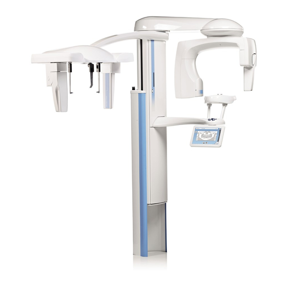
3 Main parts 3 Main parts 3.1 General view of 2D X-ray system 1. X-ray unit 2. Planmeca Romexis program 3. ProTouch desktop application (optional, see section "ProTouch desktop application" on page 17) Planmeca ProMax User's manual... -
Page 15: General View Of 3D X-Ray System
3 Main parts 3.2 General view of 3D X-ray system 1. X-ray unit 2. 3D reconstruction PC 3. Planmeca Romexis program 4. ProTouch desktop application (optional, see section "ProTouch desktop application" on page 17) 5. Ethernet switch User's manual Planmeca ProMax... -
Page 16: General View Of X-Ray Unit
19) 7. Touch screen (see section "Touch screen" on page 14) 8. Telescopic column (see section "Telescopic column" on page 12) 9. Stationary column 10. Emergency stop button (see section "Emergency stop button" on page Planmeca ProMax User's manual... -
Page 17: Sensor
3 Main parts 3.4 Sensor 1. Dimax sensor 1 3D sensor for Planmeca ProMax 3D s and Planmeca ProMax 3D Classic 2 ProFace sensor for Planmeca ProMax 3D s and Planmeca ProMax 3D Classic User's manual Planmeca ProMax... -
Page 18: Patient Supports
3.5 Patient supports 1. Bite piece 2. Chin rest 3. Adapter 4. Chin cup 5. Chin support 6. Temple supports 3.6 Telescopic column 1. Telescopic column without accessory cabinet 2. Telescopic column with accessory cabinet (three accessory boxes) Planmeca ProMax User's manual... -
Page 19: Exposure Switch
10 mm (0.4 in.). A help message will appear on the touch screen. Guide the patient away from the X-ray unit. Then release the emergency stop button. The X-ray unit will automatically restart. User's manual Planmeca ProMax... -
Page 20: Touch Screen
Home button To view up to five most recently used programs, select the home button. The most recently used program is shown first. This is the default view of the main screen. Planmeca ProMax User's manual... - Page 21 To accept a selection, select the green check mark button. Cancel button To cancel a selection and close the screen, select the red cross button. Pause button To pause a function (instead of cancelling it), select the pause button. Moving forward User's manual Planmeca ProMax...
- Page 22 The patient’s name and ID number are shown in the top right corner of the touch screen. The patient and exposure mode have to be selected in Planmeca Romexis. Checking DAP and CTDI values The estimated values for DAP (Dose Area Product) and CTDI (Computed Tomography Dose Index) are shown with black text on the touch screen before you take an exposure.
-
Page 23: Protouch Desktop Application
The application is identical to the touch screen that is integrated to the X-ray unit. The two control panels are synchronised, and you can use either or both of them. User's manual Planmeca ProMax... - Page 24 A green icon indicates that the connection is working: • A red icon indicates that the connection is not working: Restart the X-ray unit if the icon is red. To move the control panel screen, drag it with your mouse. Planmeca ProMax User's manual...
-
Page 25: Patient Positioning Controls
3.11.1 X-ray unit up / down The X-ray unit up and down buttons are used to adjust the X-ray unit to suit the height of the patient. The X-ray unit moves slowly at first, then faster. User's manual Planmeca ProMax... -
Page 26: Positioning Joystick
X-ray unit down before you position the patient in the unit. 3.11.2 Positioning joystick The positioning joystick is used for adjusting the positioning lights. It is used when the patient is positioned in the X-ray unit. Planmeca ProMax User's manual... -
Page 27: Open / Close Temple Supports
3 Main parts 3.11.3 Open / close temple supports Press the temple support button to open the temple supports in 2D imaging. The temple supports can be closed by pressing the temple support button again. User's manual Planmeca ProMax... -
Page 28: Programs
Planmeca ProMax 2D S3 and Planmeca ProMax 3D X-ray units have three joints (S3 = SCARA 3) and allow limitless imaging possibilities. Planmeca ProMax 2D S2 X-ray units have two joints (S2 = SCARA 2) and offer a more limited selection of imaging programs. -
Page 29: Interproximal
This program is optimised for interproximal imaging and a shadow of the opposite side teeth may therefore be visible in the image. 4.1.4 Orthogonal The basic imaging geometry is the same as in the standard panoramic program but the X-ray beam is perpendicular to the jaw. User's manual Planmeca ProMax... -
Page 30: Temporomandibular Joint (Tmj) Programs
4.2 Temporomandibular joint (TMJ) programs 4.2.1 Double lateral Lateral exposures of closed (1/2) and open (2/2) temporomandibular joints. • Planmeca ProMax 2D S3 & Planmeca ProMax 3D: The imaging position and angle can be adjusted. The default imaging angle is 0°. •... -
Page 31: Double Lateral-Posteroanterior
4 Programs • Planmeca ProMax 2D S3 & Planmeca ProMax 3D: The imaging position and angle can be adjusted. The default imaging angle is 0°. 4.2.3 Double lateral-posteroanterior Lateral (1/2) and posteroanterior (2/2) exposures of closed or open temporomandibular joints. The imaging angles (lateral and PA) are adjustable (default angle: 0°). -
Page 32: Sinus Programs
Three posteroanterior multi-angle TMJ exposures (left or right). The imaging angle for image no. 2 is adjustable (three imaging angles: 0° ± 7° by default). The selected imaging angle is in image no. 2. 4.3 Sinus programs 4.3.1 Posteroanterior Posteroanterior sinus exposure. Planmeca ProMax User's manual... -
Page 33: Posteroanterior Linear
4 Programs 4.3.2 Posteroanterior linear Posteroanterior linear sinus exposure. 4.3.3 Lateral Lateral exposure of the left or right sinus area. User's manual Planmeca ProMax... - Page 34 4 Programs Planmeca ProMax User's manual...
-
Page 35: Preparations For Exposure
NOTE The available sensors are shown in section "Sensor" on page 11. NOTE FOR PLANMECA PROMAX 2D X-RAY UNITS: If the sensor is attached to the cephalostat (optional), the sensor must be moved to the C-arm as described below. NOTE FOR PLANMECA PROMAX 3D X-RAY UNITS: If you wish to use a Dimax sensor, select Settings >... -
Page 36: Attaching Sensor To C-Arm
5 Preparations for exposure CAUTION Do not drop the sensor. Planmeca limited warranty does not cover damage which is due to misuse, e.g. dropping the sensor, neglect, or any cause other than ordinary use. Do not use the sensor if the shock indicator (1) is red - contact your service technician for help. - Page 37 5 Preparations for exposure 2. Turn the locking knob over the fastening mechanism. This will secure the sensor in position. User's manual Planmeca ProMax...
-
Page 38: Detaching Sensor From C-Arm
3. Push in the C-arm electrical connector button on the other side. This will make the electrical connection between the sensor and C-arm. 5.3 Detaching sensor from C-arm NOTE Do not remove the sensor during imaging process. Planmeca ProMax User's manual... - Page 39 5 Preparations for exposure 1. Push in the C-arm electrical connector. This will disconnect the electrical connection between the sensor and C-arm. 2. Turn the locking knob 180 degrees. This will release the locking mechanism. User's manual Planmeca ProMax...
-
Page 40: Preparing Planmeca Romexis
3. Carefully pull the sensor out. NOTE For safety reasons, wait for at least ten seconds before you attach a sensor again. The blue indicator light under the locking knob has to switch off first. 5.4 Preparing Planmeca Romexis • Select the patient Planmeca ProMax... -
Page 41: Preparing Patient
5 Preparations for exposure • Select the panoramic exposure Refer to the Planmeca Romexis User’s Manual for details on Romexis functions. 5.5 Preparing patient Ask the patient to remove any spectacles, hearing aids, dentures, hairpins, and personal jewellery such as earrings, necklaces and piercings as these can produce shadows or reflections in the image. -
Page 42: Panoramic Exposure
6 Panoramic exposure 6 Panoramic exposure 6.1 Before exposure Insert the temple supports into the holes in the patient support table. Planmeca ProMax User's manual... - Page 43 6 Panoramic exposure NOTE Ensure that you insert the temple supports the right way round (i.e. with the convex side facing outward as shown). • Use these patient supports. User's manual Planmeca ProMax...
- Page 44 NOTE FOR BITEWING EXPOSURES: You can use these patient supports if the patient has a very large jaw. NOTE You can use these patient supports for edentulous patients or for patients who are unable to bite. Planmeca ProMax User's manual...
-
Page 45: Selecting Exposure Settings
Select the program type from: • The drop-down menu at the top • The left of the screen Refer to section "Panoramic programs" on page 22 for details. NOTE The available options depend on the X-ray unit model. User's manual Planmeca ProMax... -
Page 46: Selecting Patient Size
Selecting child patient (XS) will automatically reduce the exposure area and patient dose. NOTE The exposure values will automatically change according to the selected patient size. NOTE The patient size can also be selected on the next screen. Planmeca ProMax User's manual... -
Page 47: Selecting Segmentation
Use the buttons on the right of the screen to select the patient entry position. • Select this button to move the C-arm to the back, away from the patient positioning area. This full view position allows you to monitor and adjust the patient’s position freely from all directions. User's manual Planmeca ProMax... - Page 48 This might be necessary if there is no space for the C-arm to move back. NOTE Planmeca ProMax 2D S2 X-ray units offer only one patient entry position. This entry position is the closed patient entry position where the C-arm is positioned around the temple supports.
-
Page 49: Positioning Patient's Head
4. Ask the patient to step forward, grasp the patient handles, stretch and straighten their back and neck, and bite the bite piece. The upper and lower incisors must be in the groove in the bite piece. User's manual Planmeca ProMax... - Page 50 If you use the chin support or the chin cup, use for example a cotton roll to ensure that the patient’s upper and lower incisors do not overlap. The positioning lights show on the patient’s face. 1. Frankfort plane light 2. Midsagittal plane light 3. Layer light Planmeca ProMax User's manual...
-
Page 51: Adjusting Patient's Head Position
The positioning lights and the illustrations on the touch screen help you to position the patient’s head correctly. NOTE The illustrations are for guidelines only. 1. To go to the next screen, select • This symbol: User's manual Planmeca ProMax... - Page 52 3. Position the patient’s Frankfort plane so that it coincides with the Frankfort plane light. To do this, adjust the tilt of the patient’s head by raising or lowering the X-ray unit with the height adjusting buttons. The patient’s back and neck must be straight. Planmeca ProMax User's manual...
- Page 53 6 Panoramic exposure • The Frankfort plane light is located inside the column. The light’s position can be adjusted if needed. This is done by rotating the thumb wheel below the light slot. User's manual Planmeca ProMax...
- Page 54 NOTE The layer light is switched off when Autofocus is selected. Refer to section "Taking an exposure with Autofocus (Planmeca ProMax 2D S3 and Planmeca ProMax 3D X-ray units)" on page 55 for details. 5. Check that the midsagittal plane light and the Frankfort plane light are still correctly positioned.
-
Page 55: Selecting Jaw Size And Shape
Jaw shape of the patient (rows): 1. V-shaped 2. Standard 3. U-shaped NOTE The jaw size will automatically change according to the selected patient size (XS = 1, S & M & L = 2, XL = 3). User's manual Planmeca ProMax... -
Page 56: Selecting Multiview (Planmeca Promax 3D X-Ray Units)
NOTE MultiView is an optional feature for Planmeca ProMax 3D X-ray units. Use this button to select the MultiView imaging mode. This function allows you to adjust the viewing angle in the Planmeca Romexis program. • Panoramic layers with MultiView (button selected) -
Page 57: Adjusting Exposure Values For Current Exposure
Factory presets for panoramic exposures PATIENT SIZE kV VALUE mA VALUE X-ray units with Dimax sensor Child (XS) Small adult (S) Medium-sized adult (M) Large adult (L) Extra large adult (XL) 12.5 X-ray units with 3D sensor SmartPan Child (XS) User's manual Planmeca ProMax... -
Page 58: Selecting Dynamic Exposure Control (Dec) (Planmeca Promax 2D X-Ray Units)
NOTE You can adjust the preset exposure values permanently as described in section "Programs" on page 22. 6.8 Selecting Dynamic Exposure Control (DEC) (Planmeca ProMax 2D X- ray units) NOTE Dynamic Exposure Control (DEC) is an optional feature for Planmeca ProMax 2D X-ray units. -
Page 59: Adjusting Dec Density
100% (default setting). 6.9 Taking an exposure NOTE Make sure that you have selected the correct patient and exposure mode in the Planmeca Romexis program. 1. Make sure that the Exposure tab is selected. User's manual Planmeca ProMax... - Page 60 Additionally, a radiation warning symbol is shown on the touch screen. NOTE Maintain audio and visual contact with the patient and X-ray unit during exposure. If the C-arm stops moving during exposure, or moves in an erratic way, release the exposure button immediately. Planmeca ProMax User's manual...
-
Page 61: Taking An Exposure With Autofocus (Planmeca Promax 2D S3 And Planmeca Promax 3D X-Ray Units)
6 Panoramic exposure 6. The image is shown on the computer screen. Note that you must accept the image in the Planmeca Romexis program. 7. Guide the patient away from the X-ray unit. 6.10 Taking an exposure with Autofocus (Planmeca ProMax 2D S3 and... - Page 62 If needed, you can adjust the layer position manually by using the plus or minus sign on the touch screen. The new position is shown with a red line on the image. NOTE Make sure that the patient does not move between exposures. Planmeca ProMax User's manual...
- Page 63 If the C-arm stops moving during exposure, or moves in an erratic way, release the exposure button immediately. 5. The image is shown on the computer screen. Note that you must accept the image in the Planmeca Romexis program. 6. Guide the patient away from the X-ray unit. User's manual...
-
Page 64: Temporomandibular Joint (Tmj) Exposure
Double TMJ programs produce closed and open views of the left and right temporomandibular joints. Three angle TMJ programs produce three exposures with different angles from the left or right temporomandibular joint. 7.1 Before exposure Insert the temple supports into the holes in the patient support table. Planmeca ProMax User's manual... -
Page 65: Selecting Exposure Settings
• Use these patient supports. 7.2 Selecting exposure settings Refer to section "Touch screen" on page 14 for general information on how to make or cancel selections on the touch screen. User's manual Planmeca ProMax... -
Page 66: Selecting Program
Refer to section "Temporomandibular joint (TMJ) programs" on page 24 for details. NOTE The available options depend on the X-ray unit model. 7.2.3 Selecting patient size Select the patient size as described in section "Selecting patient size" on page 77. Planmeca ProMax User's manual... -
Page 67: Selecting Jaw Side(S)
7.2.4 Selecting jaw side(s) Use this button to select the right, left or both jaw sides. 7.2.5 Selecting imaging angle (Planmeca ProMax 2D S3 and Planmeca ProMax 3D X- ray units) Use the arrow buttons to select the imaging angle for this exposure. -
Page 68: Positioning Patient's Head
The positioning lights for the midsagittal plane, Frankfort plane (and TMJ position, depending on unit configuration) show on the patient’s face. The lights will automatically switch off after two minutes. To switch them off earlier, press the positioning joystick. Planmeca ProMax User's manual... -
Page 69: Adjusting Patient's Head Position (Planmeca Promax 2D S2 X-Ray Units)
1. Press the thumb wheel on the underside of the patient support table. 2. Press any of the positioning controls (button or joystick). 7.3.3 Adjusting patient’s head position (Planmeca ProMax 2D S2 X-ray units) The positioning lights and the illustrations on the touch screen help you to position the patient’s head correctly. - Page 70 7 Temporomandibular joint (TMJ) exposure 2. Position the patient’s midsagittal plane so that it coincides with the midsagittal plane light. Planmeca ProMax User's manual...
- Page 71 The Frankfort plane light is located inside the column. The light’s position can be adjusted if needed. This is done by rotating the thumb wheel below the light slot. User's manual Planmeca ProMax...
-
Page 72: Adjusting Patient's Head Position (Planmeca Promax 2D S3 And Planmeca Promax 3D X-Ray Units)
FOR POSTEROANTERIOR EXPOSURES: It is not possible to adjust the imaging position. 7.3.4 Adjusting patient’s head position (Planmeca ProMax 2D S3 and Planmeca ProMax 3D X-ray units) The positioning lights and the illustrations on the touch screen help you to position the patient’s head correctly. - Page 73 7 Temporomandibular joint (TMJ) exposure • This symbol: • The forward button: 2. Position the patient’s midsagittal plane so that it coincides with the midsagittal plane light. User's manual Planmeca ProMax...
- Page 74 X-ray unit with the height adjusting buttons. The patient’s back and neck must be straight. • The Frankfort plane light is located inside the column. The light’s position can be adjusted if needed. This is done by rotating the thumb wheel below the light slot. Planmeca ProMax User's manual...
-
Page 75: Adjusting Exposure Values For Current Exposure
NOTE Always try to minimise the radiation dose to the patient. The following tables show the preset exposure values. Factory presets for lateral and lateral-PA TMJ exposures PATIENT SIZE kV VALUE mA VALUE Child (XS) User's manual Planmeca ProMax... -
Page 76: Taking An Exposure In Double Tmj Programs
7.5 Taking an exposure in double TMJ programs NOTE Make sure that you have selected the correct patient and exposure mode in the Planmeca Romexis program. 7.5.1 First exposure - jaw closed (1/2) 1. Select the radiation symbol or the forward button. - Page 77 If the C-arm stops moving during exposure, or moves in an erratic way, release the exposure button immediately. NOTE If needed, you can stop the imaging process by touching the red cross button after you have taken the first exposure. User's manual Planmeca ProMax...
-
Page 78: Second Exposure - Jaw Open (2/2)
3. Press and hold down the exposure button for the duration of the second exposure. The C-arm moves around the patient’s head and the exposure is taken in the same way as the first exposure. Planmeca ProMax User's manual... -
Page 79: Taking An Exposure In Three Angle Tmj Programs
7 Temporomandibular joint (TMJ) exposure 4. The image is shown on the computer screen. • Note that you must accept the image in the Planmeca Romexis program. 5. Guide the patient away from the X-ray unit. 7.6 Taking an exposure in three angle TMJ programs... - Page 80 5. The image is shown on the computer screen. • Note that you must accept the image in the Planmeca Romexis program. 6. Guide the patient away from the X-ray unit. Planmeca ProMax...
-
Page 81: Sinus Exposure
8 Sinus exposure 8 Sinus exposure This procedure will produce an exposure of the maxillary sinuses. 8.1 Before exposure Insert the temple supports into the holes in the patient support table. User's manual Planmeca ProMax... -
Page 82: Selecting Exposure Settings
• Use these patient supports. 8.2 Selecting exposure settings Refer to section "Touch screen" on page 14 for general information on how to make or cancel selections on the touch screen. Planmeca ProMax User's manual... -
Page 83: Selecting Program
Refer to section "Sinus programs" on page 26 for details. NOTE The available options depend on the X-ray unit model. 8.3 Selecting patient size Select the patient size as described in section "Selecting patient entry position" on page 78. User's manual Planmeca ProMax... -
Page 84: Selecting Jaw Side For Lateral Exposures (Planmeca Promax 2D S3 And Planmeca Promax 3D X-Ray Units)
8 Sinus exposure 8.4 Selecting jaw side for lateral exposures (Planmeca ProMax 2D S3 and Planmeca ProMax 3D X-ray units) Use this button to select the right or left jaw side. 8.5 Patient positioning 8.5.1 Selecting patient entry position Select the patient entry position as described in section "Selecting patient entry position"... -
Page 85: Adjusting Patient's Head Position
1. Press the thumb wheel on the underside of the patient support table. 2. Press any of the positioning controls (button or joystick). 8.5.3 Adjusting patient’s head position The positioning lights and the illustrations on the touch screen help you to position the patient’s head correctly. User's manual Planmeca ProMax... - Page 86 1. To go to the next screen, select • This symbol: • The forward button: 2. Position the patient’s midsagittal plane so that it coincides with the midsagittal plane light. 3. Position the patient’s Frankfort plane as follows. Planmeca ProMax User's manual...
- Page 87 Frankfort plane light as a reference line, adjust the tilt of the patient’s head by raising or lowering the X- ray unit with the height adjusting buttons. The patient’s back and neck must be straight. User's manual Planmeca ProMax...
-
Page 88: Adjusting Exposure Values For Current Exposure
Factory presets for posteroanterior sinus exposures PATIENT SIZE kV VALUE mA VALUE Child (XS) Small adult (S) Factory presets for posteroanterior sinus exposures PATIENT SIZE kV VALUE mA VALUE Medium-sized adult (M) Large adult (L) Extra large adult (XL) Planmeca ProMax User's manual... -
Page 89: Taking An Exposure
NOTE Make sure that you have selected the correct patient and exposure mode in the Planmeca Romexis program. 1. Select the radiation symbol or the forward button. Green lights flash on the touch screen and exposure button when the X- ray system is getting ready for an exposure. - Page 90 If the C-arm stops moving during exposure, or moves in an erratic way, release the exposure button immediately. 5. The image is shown on the computer screen. Note that you must accept the image in the Planmeca Romexis program. 6. Guide the patient away from the X-ray unit. Planmeca ProMax...
-
Page 91: Settings
Settings that can be entered by the user: • User • Program • About Settings that can be entered by service personnel only (password required): • Technical To return to the main screen, select the settings symbol at the top left corner. User's manual Planmeca ProMax... -
Page 92: User Settings
1. Select User > 1200 Time and Date > 1210 Set System Time and Time / Date Display Format > Time Display Format. 2. Select the display format you wish to use. 3. Select the green check mark button. Planmeca ProMax User's manual... - Page 93 2. Use the plus and minus buttons to change the time. 3. Select the green check mark button. NOTE The time is set to the local time at the factory. Change the time setting to show the correct time before you start using the X-ray unit. User's manual Planmeca ProMax...
-
Page 94: Operational Settings (1300)
1. Select User > 1300 Operational Settings > 1310 Use Mode. 2. Select the mode you wish to use. In demo mode you can practice or demonstrate the functions of the X- ray unit without radiation and PC connection. 3. Select the green check mark button. Planmeca ProMax User's manual... - Page 95 This might be necessary if there is no space for the C-arm to move back. NOTE Planmeca ProMax 2D S2 X-ray units offer only one patient entry position. This entry position is the closed patient entry position where the C-arm is positioned around the temple supports.
- Page 96 Note, however, that the automatic function works only if the exposure button is pressed and held down for the entire duration of the exposure. 3. Select the green check mark button. Planmeca ProMax User's manual...
- Page 97 Note that the setting affects all indicator lights that are connected to your X-ray system (indicator light on the hand-held exposure switch, wall exposure switch(es) and remote exposure lamp). 3. Select the green check mark button. User's manual Planmeca ProMax...
-
Page 98: Network Settings (1400)
4. Move to a protected area. 5. Press and hold down the exposure button for the duration of the exposure. The C-arm will not move when you take a test exposure. 6. Select the green check mark button. Planmeca ProMax User's manual... -
Page 99: Clinic Management (1600)
X-ray tube) reappears after a successful seasoning process. 9.1.6 Clinic Management (1600) Select User > 1600 Clinic Management to view the network settings for the Planmeca Romexis Clinic Management module. NOTE Only a service technician or local administrator may change the settings. - Page 100 5. Use the minus or plus buttons to set the exposure values you wish to use. 6. Select the green check mark button. 7. Repeat for another program type, patient size or image resolution (3D) if needed. 8. Select the green check mark button. Planmeca ProMax User's manual...
-
Page 101: Program Features (2200)
Bitewing Panoramic Program (True extraoral bitewing program) • Advanced Panoramic Programs (Additional 2D panoramic, TMJ and sinus programs) • 2D Tomography (2D tomographic programs, for Planmeca ProMax 2D only) • Panoramic DEC (Dynamic Exposure Control for 2D panoramic programs with Dimax sensor) •... - Page 102 • 3D Endodontic Imaging Mode (Endodontic image resolution for small 3D image volumes) • Braces Protocol (3D Braces program, for Planmeca ProMax 3D Classic only) • 3D Classic Extended Volume (Extended 3D image volume for 3D Teeth program, for Planmeca ProMax 3D Classic only) •...
-
Page 103: Reset To Factory Defaults (2500)
Information to view the set-up or current software versions of the X-ray unit. To view software build information: Select About > 4100 Component Information > Show Detailed Build Info to view details about the software build. User's manual Planmeca ProMax... -
Page 104: Archive (4200)
Select About > 4200 Archive > Exposure Statistics to view statistical data about the X-ray unit. 9.3.3 Product Registration (4300) To register the X-ray unit on Planmeca’s website: 1. Select About > 4300 Product Registration. 2. Do one of the following: 1. -
Page 105: Help Messages
Patient safety area violation in Check the slice count and / or tomo slice 1. step between slices. H132 Patient safety area violation in Check the slice count and / or tomo slice 2. step between slices. User's manual Planmeca ProMax... - Page 106 Select another exposure mode in conflict with the selected X-ray Planmeca Romexis. unit program. H180 DEC is not available. H181 The imaging process was cancelled in Planmeca Romexis. H182 Timeout in image data Exposure was interrupted. transmission. Contact your service technician for help. H183 The attached sensor is not Change the sensor.
- Page 107 Eeprom reading failed. Retry or contact your service technician for help. H199 The 3D reconstruction PC does Upgrade the 3D reconstruction not support the CALM algorithm. PC or deactivate the CALM licence. Contact your service technician for help. User's manual Planmeca ProMax...
-
Page 108: Error Messages
The X-ray unit will not accept any commands from the user until the error message is cleared from the touch screen. Guide the patient away from the X-ray unit. Then clear the message by touching the green check mark. Planmeca ProMax User's manual... -
Page 109: Cleaning And Disinfection
NOTE Switch the X-ray unit off before cleaning or disinfection. NOTE Use a Planmeca approved cleaning agent and surface disinfectant. The products are categorised here as cleaning agents and / or disinfectants according to the information provided by the manufacturers. -
Page 110: Patient Supports, Patient Handles And Touch Screen
Optim Blue Wipes 12.1 Patient supports, patient handles and touch screen Wipe these parts after each patient using a Planmeca approved surface disinfectant. Use a Planmeca approved cleaning agent for cleaning stains and dirt if needed. • Panoramic patient supports •... - Page 111 12 Cleaning and disinfection • Patient handles • Touch screen User's manual Planmeca ProMax...
-
Page 112: Other Surfaces
12 Cleaning and disinfection 12.2 Other surfaces Wipe the other surfaces regularly using a Planmeca approved surface disinfectant. Use a Planmeca approved cleaning agent for cleaning stains and dirt if needed. Planmeca ProMax User's manual... - Page 113 The impression plate (the upper component in the figure above) is a single- use item. Do not reuse it for another patient. NOTE The parts in the figure below can be autoclaved at 134°C (273°F). The parts can be autoclaved up to 100 times. User's manual Planmeca ProMax...
-
Page 114: Service
13 Service 13 Service The X-ray unit must be checked by a qualified Planmeca service technician once a year or after every 10 000 exposures (if this is sooner). This will guarantee patient and user safety and ensure consistent image quality. -
Page 115: Disposal
14 Disposal In order to reduce the environmental load over the product’s entire lifecycle, Planmeca’s products are designed to be as safe as possible to manufacture, use and dispose of. Parts which can be recycled should always be taken to the appropriate processing centers, after hazardous waste has been removed. -
Page 116: Technical Data For Planmeca Promax Product Family
15 Technical data for Planmeca ProMax product family 15 Technical data for Planmeca ProMax product family Classification Medical Device Directive 93/42/EEC (Class IIb) RoHS 2011/65/EU IEC 60601-1 Class I, type B CISPR 11 Class B IP Classification IP20 Applied parts (according to IEC 60601-1: 2012) - Page 117 15 Technical data for Planmeca ProMax product family 3D s / 3D Classic / 3D Plus or 3D Mid with X-ray tube D-054SB or 3D Max with X-ray tube D-067SB 3D: 1 - 14 mA ±10% Pan / SmartPan: 1 - 16 mA ±10% Scanning ceph: 1 - 16 mA ±10%...
- Page 118 15 Technical data for Planmeca ProMax product family 3D / SmartPan • 3D s / 3D Classic: 528 mm (20.7 in.) • 3D Plus or 3D Mid with X-ray tube D-054SB / 3D Max with X-ray tube D-067SB: 600 mm (23.6 in.)
- Page 119 15 Technical data for Planmeca ProMax product family Scanning ceph 26 kg (57 lb) Planmeca ProCeph 20 kg (44 lb) Environmental requirements Transport: Temperature -20°C - +60°C (-4°F - +140°F) Relative humidity 10 - 90% RH (non-condensing) Air pressure 700 - 1060 hPa...
- Page 120 15 Technical data for Planmeca ProMax product family Optimum colour temperature Approx. 6500 Kelvin Frequency for fluorescent lamps 100 Hz Even and uniform lighting No natural light Original manufacturer Planmeca Oy, Asentajankatu 6, FIN-00880, Helsinki, Finland Phone: +358 20 7795 500, Fax: +358 20 7795 555, www.planmeca.com...
- Page 122 Planmeca Oy | Asentajankatu 6 | 00880 Helsinki | Finland tel. +358 20 7795 500 | fax +358 20 7795 555 | sales@planmeca.com | www.planmeca.com...
Need help?
Do you have a question about the ProMax 2D and is the answer not in the manual?
Questions and answers
Temple supports won’t operate with button, will not close on patient, just started yesterday
If the temple supports on a Planmeca ProMax 2D are not operating with the button and will not close, possible issues could include:
1. A malfunctioning temple support button.
2. A power or electrical issue preventing the mechanism from working.
3. An obstruction preventing movement.
4. A system error requiring technician assistance.
Contact a service technician for help.
This answer is automatically generated