Planmeca ProMax 3D s User Manual
Hide thumbs
Also See for ProMax 3D s:
- User manual (110 pages) ,
- Technical manual (378 pages) ,
- User manual (84 pages)
Table of Contents
Advertisement
Advertisement
Table of Contents

Related Manuals for Planmeca ProMax 3D s


Summary of Contents for Planmeca ProMax 3D s
- Page 1 Planmeca ProMax ® 3D s & 3D Classic user's manual 3D imaging...
-
Page 3: Table Of Contents
Touch screen ........................17 6.10 ProTouch desktop application ....................20 6.11 Patient positioning controls ....................21 PLANMECA PROMAX 3D s PROGRAMS ................23 3D Dental ..........................23 3D Models ..........................23 PLANMECA PROMAX 3D CLASSIC PROGRAMS .............. 24 3D Dental ..........................24 3D Models .......................... - Page 4 IEC 60364 - equipment is used according to the operating instructions. Planmeca pursues a policy of continual product development. Although every effort is made to produce up-to-date product documentation this publication should not be regarded as an infallible guide to current specifications. We reserve the right to make changes without prior notice.
-
Page 5: Introduction
You need a PC with the Planmeca Romexis program in order to save, view and modify the images. Make sure that you are fully acquainted with the appropriate radiation protection measures and these instructions before you use the X-ray unit. -
Page 6: Associated Documentation
User’s Manual, Original English publication: 10014593 • Technical Manual, Original English publication: 10037884 NOTE The User’s Manuals are available on Planmeca’s website. • For X-ray units, select Material bank > Manuals > Imaging. • For software products, select Material bank >... -
Page 7: Symbols On Product Labels
(Standard ISO 7010-M002) Emergency stop (Standard IEC 60601-1) Warning; Electricity (Standard ISO 7010-W012) Electrostatic sensitive device (Standard IEC 60417) Warning; Hot surface (Standard ISO 7010-W017) General warning sign (Standard ISO 7010-W001) User’s Manual (3D Imaging) Planmeca ProMax 3D s & 3D Classic... -
Page 8: Symbols On X-Ray Units With Detachable Power Supply Cord
Separate collection for electrical and electronic equipment (Directive 2002/96/EC WEEE) Attention, consult accompanying documents (Standard IEC 60601-1) Alternating current (Standard IEC 60417) Electrostatic sensitive device (Standard IEC 60417) Warning; Hot surface (Standard ISO 7010-W017) Planmeca ProMax 3D s & 3D Classic User’s Manual (3D Imaging) -
Page 9: Safety Precautions
The patient positioning lights are laser lights. Do not stare into the laser beam. CAUTION Do not drop the sensor. Planmeca limited warranty does not cover damage which is due to misuse, e.g. dropping the sensor, neglect, or any cause other than ordinary use. - Page 10 NOTE If the X-ray system is not connected to an Uninterruptible Power Supply (UPS), switch the X-ray unit off and disconnect the PCs from the mains during lightning storms. Planmeca ProMax 3D s & 3D Classic User’s Manual (3D Imaging)
- Page 11 Contact your service technician if you notice a decrease in image quality. NOTE Contact your service technician if you have taken an exposure but the image does not appear in the Planmeca Romexis program. The last ten images can be manually imported into Romexis. NOTE Do not handle liquids near or on the X-ray unit.
- Page 12 Do not touch the metal parts in the middle of the tube head. They might be hot. NOTE FOR PROFACE SENSOR: Do not touch the glass windows. Fingerprints or other stains on the glass surface destroy image quality. Prof_6C.eps Planmeca ProMax 3D s & 3D Classic User’s Manual (3D Imaging)
-
Page 13: Switching X-Ray Unit On
The on / off switch is located on the underside of the stationary column top. NOTE To prolong the lifetime of your X-ray unit, always switch the X-ray unit off when it is not in active use. User’s Manual (3D Imaging) Planmeca ProMax 3D s & 3D Classic... -
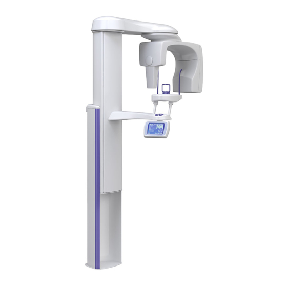
Page 14: Main Parts
6.1 General view of X-ray system 3 & 4 X-ray unit 3D reconstruction PC Planmeca Romexis program ProTouch desktop application (optional, see section 6.10 “ProTouch desktop application” on page 20) Ethernet switch Planmeca ProMax 3D s & 3D Classic User’s Manual (3D Imaging) -
Page 15: General View Of X-Ray Unit
Touch screen (see section 6.9 “Touch screen” on page 17) Telescopic column (see section 6.6 “Telescopic column” on page 15) 10 Stationary column 11 Emergency stop button (see section 6.8 “Emergency stop button” on page 16) User’s Manual (3D Imaging) Planmeca ProMax 3D s & 3D Classic... -
Page 16: Sensor
6 MAIN PARTS 6.3 Sensor 3D sensor for Planmeca ProMax 3D s 3D sensor for Planmeca ProMax 3D Classic ProFace sensor for Planmeca ProMax 3D s and Planmeca ProMax 3D Classic Planmeca ProMax 3D s & 3D Classic User’s Manual (3D Imaging) -
Page 17: Tube Head
6 MAIN PARTS 6.4 Tube head Non-rotating tube head Rotating tube head User’s Manual (3D Imaging) Planmeca ProMax 3D s & 3D Classic... -
Page 18: Patient Supports
6 MAIN PARTS 6.5 Patient supports 6.5.1 Head supports (A or B) Adjustable head support 1. Head band 25 Temple pads for children 2. Support bars Fastening straps Support bars Planmeca ProMax 3D s & 3D Classic User’s Manual (3D Imaging) -
Page 19: Telescopic Column
6 MAIN PARTS 6.5.2 Chin supports Chin cup Chin support Adjustable adapter 6.6 Telescopic column Telescopic column without accessory cabinet Telescopic column with accessory cabinet (three accessory boxes) User’s Manual (3D Imaging) Planmeca ProMax 3D s & 3D Classic... -
Page 20: Exposure Switch
A help message will appear on the touch screen. Guide the patient away from the X-ray unit. Then release the emergency stop button. The X-ray unit will automatically restart. Planmeca ProMax 3D s & 3D Classic User’s Manual (3D Imaging) -
Page 21: Touch Screen
• Program group button(s): To view all the programs that are available for a program group, select the program group button. User’s Manual (3D Imaging) Planmeca ProMax 3D s & 3D Classic... - Page 22 • Moving backward: To go back to a previous screen, select a previous symbol at the bottom of the screen. Planmeca ProMax 3D s & 3D Classic User’s Manual (3D Imaging)
- Page 23 Checking patient’s name and ID number: The patient’s name and ID number are shown in the top right corner of the touch screen. The patient and exposure mode have to be selected in Planmeca Romexis. • Checking DAP and CTDI values:...
-
Page 24: Protouch Desktop Application
To move the control panel screen, drag it with your mouse. To close the application, click on the small red cross in the top right corner of the screen. Planmeca ProMax 3D s & 3D Classic User’s Manual (3D Imaging) -
Page 25: Patient Positioning Controls
If something is in danger of becoming trapped, release the button immediately to stop the movement. Clear any obstruction before pressing the button again. User’s Manual (3D Imaging) Planmeca ProMax 3D s & 3D Classic... - Page 26 Open / close temple supports Press the temple support button to open the temple supports in 2D imaging. The temple supports can be closed by pressing the temple support button again. Planmeca ProMax 3D s & 3D Classic User’s Manual (3D Imaging)
-
Page 27: Planmeca Promax 3D S Programs
3 x Ø50 x H50 mm 3 x Ø50 x H80 mm 7.2 3D Models 7.2.1 Volume size Program Ø50 mm IMPRESSION Ø50 x H40 mm PLASTER CAST Ø50 x H40 mm User’s Manual (3D Imaging) Planmeca ProMax 3D s & 3D Classic... -
Page 28: Planmeca Promax 3D Classic Programs
* = Volume diameter can be extended to 110 mm 8.2 3D Models 8.2.1 Volume size Program Ø80 mm IMPRESSION Ø80 x H40 mm PLASTER CAST Ø80 x H40 mm Planmeca ProMax 3D s & 3D Classic User’s Manual (3D Imaging) -
Page 29: Patient Exposure
Do not touch the glass windows. Fingerprints or other stains on the glass surface destroy image quality. Prof_6C.eps CAUTION Do not drop the sensor. Planmeca limited warranty does not cover damage which is due to misuse, e.g. dropping the sensor, neglect, or any cause other than ordinary use. - Page 30 NOTE For safety reasons, wait for at least ten seconds before you attach a sensor again. The blue indicator light under the locking knob has to switch off first. Planmeca ProMax 3D s & 3D Classic User’s Manual (3D Imaging)
- Page 31 Ensure that you insert the support bars the right way round. Head support A: Attaching adjustable head support If you are using the adjustable head support, slide it onto the support bars. User’s Manual (3D Imaging) Planmeca ProMax 3D s & 3D Classic...
- Page 32 50 mm (2 in.). Straps with a free length (i.e. when they are not stretched) of over 255 mm (10 in.) do not support the patient’s head firmly. Planmeca ProMax 3D s & 3D Classic User’s Manual (3D Imaging)
- Page 33 The lower the patient is positioned, the higher the image position will Use these patient supports. User’s Manual (3D Imaging) Planmeca ProMax 3D s & 3D Classic...
- Page 34 Use the highest position and a chin cup when taking exposures of the teeth area or other anatomical structures that are at this height. Teeth program Tooth program TEETH AREA: Chin cup up Planmeca ProMax 3D s & 3D Classic User’s Manual (3D Imaging)
- Page 35 Use the lowest position and a chin support under the nose when taking ear or temporomandibular joint (TMJ) exposures. Tooth program Teeth program EAR or TMJ: Chin support down Jossu 5 User’s Manual (3D Imaging) Planmeca ProMax 3D s & 3D Classic...
-
Page 36: Preparing Patient
9 3D PATIENT EXPOSURE 9.1.4 Preparing Planmeca Romexis First select the patient. Then select the 3D exposure. Refer to the Planmeca Romexis User’s Manual for details on Romexis functions. 9.2 Preparing patient Ask the patient to remove any spectacles, hearing aids,... -
Page 37: Selecting Exposure Settings
9.3.1 Selecting program Select the 3D program you wish to use. Refer to • section 7 “PLANMECA PROMAX 3D s PROGRAMS” on page 23 or • section 8 “PLANMECA PROMAX 3D CLASSIC PROGRAMS” on page 24 for details. - Page 38 9 3D PATIENT EXPOSURE 9.3.3 Selecting extended volume diameter NOTE This is an optional feature for Planmeca ProMax 3D Classic X-ray units. It is available for the front-most volume position in the 3D Teeth program. Use this button to select the extended volume diameter.
- Page 39 The available options depend on the selected program. NOTE In 3D Double Scan and 3D Triple Scan programs the selected area is the primary image volume. The other image volume(s) adjoin(s) the primary image volume. User’s Manual (3D Imaging) Planmeca ProMax 3D s & 3D Classic...
- Page 40 Use this button if you wish to reduce the diameter of the adjoining image volume(s). NOTE All image volumes are the same height. Planmeca ProMax 3D s & 3D Classic User’s Manual (3D Imaging)
-
Page 41: Patient Positioning
• You can use fastening straps for additional head support if needed. Refer to section 9.1.2 “Attaching head support” on page 27 for details. User’s Manual (3D Imaging) Planmeca ProMax 3D s & 3D Classic... -
Page 42: Selecting Exposure Values
The available options depend on the selected program and X-ray unit model. NOTE The exposure values will automatically change according to the selected patient size, image resolution and ULD setting. Planmeca ProMax 3D s & 3D Classic User’s Manual (3D Imaging) - Page 43 Factory presets for image resolution Normal mA VALUE PATIENT SIZE kV VALUE mA VALUE WITH ULD Child (XS) Small adult (S) Medium-sized adult (M) Large adult (L) Extra large adult (XL) User’s Manual (3D Imaging) Planmeca ProMax 3D s & 3D Classic...
- Page 44 Select the green check mark button. NOTE You can adjust the preset exposure values permanently as described in section 12.2.1 “Programs (2100)” on page 75. Planmeca ProMax 3D s & 3D Classic User’s Manual (3D Imaging)
-
Page 45: Selecting Patient Movement Correction
9 3D PATIENT EXPOSURE 9.6 Selecting patient movement correction Use this button to select the Planmeca CALM patient movement correction function. This is an algorithm that detects patient movement during exposure and then compensates for the effects of the movement during image reconstruction. -
Page 46: Adjusting Volume Position
Press any of the positioning controls (button or joystick). The lights will automatically switch off after two minutes. To switch them off earlier, press the positioning joystick. Planmeca ProMax 3D s & 3D Classic User’s Manual (3D Imaging) - Page 47 Adjustable adapter NOTE If only the upper jaw half is selected, the lower edge of the image volume is positioned 30 mm (1.2 in.) above the volume bottom light. User’s Manual (3D Imaging) Planmeca ProMax 3D s & 3D Classic...
- Page 48 (i.e. the image volume center as seen from the front) will move accordingly on your patient’s face. Left Right Right Left Positioning joystick (front light = X laser) Planmeca ProMax 3D s & 3D Classic User’s Manual (3D Imaging)
- Page 49 The side light (i.e. the image volume center as seen from the side) will move accordingly on your patient’s face. Thumb wheel (side light = Y laser) Front Back Back Positioning joystick (side light = Y laser) Front User’s Manual (3D Imaging) Planmeca ProMax 3D s & 3D Classic...
-
Page 50: Taking A Scout Image Or 2D Views (Lat, Pa Or Lat-Pa)
Make sure that you have selected the correct patient and exposure mode in the Planmeca Romexis program. Select the view you wish to take. To take LAT-PA views, select both buttons (LAT and PA). Planmeca ProMax 3D s & 3D Classic User’s Manual (3D Imaging) - Page 51 The image is shown on the computer screen. If needed, you can readjust the volume position as shown below. • For scout images: Use the plus and minus signs that appear on the touch screen. User’s Manual (3D Imaging) Planmeca ProMax 3D s & 3D Classic...
- Page 52 9.8.2 “Moving image volume horizontally (X and Y lasers)” on page 44. Then take a new exposure as described above. Repeat the procedure until the image volume is in the correct place. Planmeca ProMax 3D s & 3D Classic User’s Manual (3D Imaging)
-
Page 53: Taking A 3D Exposure
Maintain audio and visual contact with the patient and X-ray unit during exposure. If the C-arm stops moving during exposure, or moves in an erratic way, release the exposure button immediately. User’s Manual (3D Imaging) Planmeca ProMax 3D s & 3D Classic... - Page 54 Remove the fastening straps (if used). Release the patient from the head support by turning the adjusting knob at the top. Guide the patient away from the X-ray unit. Planmeca ProMax 3D s & 3D Classic User’s Manual (3D Imaging)
-
Page 55: Face Photo
Do not use the chin cup or the fastening straps when taking 3D face photos. Select the patient and the 3D exposure as described in section 9.1.4 “Preparing Planmeca Romexis” on page 32. 10.2 Patient positioning Select the ProFace program (Special Programs >... - Page 56 If you wish to see the patient’s ears clearly in the photo, position the patient’s head so that the head support is at the back of the head as shown here. Ask the patient to grasp the patient handles. Planmeca ProMax 3D s & 3D Classic User’s Manual (3D Imaging)
-
Page 57: Selecting Exposure Settings
(Y laser). • Select the button again if you wish to rotate the C-arm back to the original position. User’s Manual (3D Imaging) Planmeca ProMax 3D s & 3D Classic... -
Page 58: Taking A 3D Face Photo
Ask the patient to either keep their eyes shut or to focus them on a fixed point so that the eyes are not half open in the image. Planmeca ProMax 3D s & 3D Classic User’s Manual (3D Imaging) - Page 59 The photo is shown on the computer screen. Release the patient from the head support by turning the adjusting knob at the top. Guide the patient away from the X-ray unit. User’s Manual (3D Imaging) Planmeca ProMax 3D s & 3D Classic...
-
Page 60: Model Exposure
Calibration pin pin has to be pushed in thicker end first. The middle (part number rim has to be flush with the top edge of the calibration 10031265) cup. Planmeca ProMax 3D s & 3D Classic User’s Manual (3D Imaging) - Page 61 11.1.2 Selecting settings On the X-ray unit, select the program. • For impression material select 3D Models > Impression. • For plaster material select 3D Models > Plaster Cast. User’s Manual (3D Imaging) Planmeca ProMax 3D s & 3D Classic...
- Page 62 Place the calibration cup on the polystyrene disc so that the volume center lights cross in the middle of the cup. Volume center lights Calibration cup on polystyrene disc Planmeca ProMax 3D s & 3D Classic User’s Manual (3D Imaging)
- Page 63 X-ray system is getting ready for an exposure. The green lights stop flashing and stay on continuously when the X-ray system is ready for an exposure. Move to a protected area. User’s Manual (3D Imaging) Planmeca ProMax 3D s & 3D Classic...
-
Page 64: Taking An Exposure Of An Impression Or Plaster Cast
Additionally, a radiation warning symbol is shown on the touch screen. In the Planmeca Romexis program, enter a name for this material and select OK. NOTE The calibration exposure values are automatically included at the beginning of the name. - Page 65 Select the exposure values that you used in the calibration process for this material. Refer to section 9.5.3 “Adjusting exposure values for current exposure” on page 39 if you need to adjust the preset exposure values. User’s Manual (3D Imaging) Planmeca ProMax 3D s & 3D Classic...
- Page 66 40 mm (1.6 in.). Planmeca ProMax 3D Classic 40 mm Volume center lights Impression on polystyrene disc If not yet done, select the patient in the Planmeca Romexis program. Planmeca ProMax 3D s & 3D Classic User’s Manual (3D Imaging)
- Page 67 During exposure yellow radiation warning lights illuminate on the exposure switch and on the touch screen, and you hear a radiation warning tone. Additionally, a radiation warning symbol is shown on the touch screen. User’s Manual (3D Imaging) Planmeca ProMax 3D s & 3D Classic...
- Page 68 11 3D MODEL EXPOSURE The image is shown on the computer screen. NOTE The Romexis function Model Capture creates surface models (instead of voxel data images). Planmeca ProMax 3D s & 3D Classic User’s Manual (3D Imaging)
-
Page 69: Settings
About Settings that can be entered by service personnel only (password required): • Technical To return to the main screen, select the settings symbol at the top left corner. User’s Manual (3D Imaging) Planmeca ProMax 3D s & 3D Classic... -
Page 70: User Settings
Select User > 1200 Time and Date > 1210 Set System Time and Time / Date Display Format > Time Display Format. Select the display format you wish to use. Select the green check mark button. Planmeca ProMax 3D s & 3D Classic User’s Manual (3D Imaging) - Page 71 Select the green check mark button. NOTE The time is set to the local time at the factory. Change the time setting to show the correct time before you start using the X-ray unit. User’s Manual (3D Imaging) Planmeca ProMax 3D s & 3D Classic...
- Page 72 Select the mode you wish to use. In demo mode you can practice or demonstrate the functions of the X-ray unit without radiation and PC connection. Select the green check mark button. Planmeca ProMax 3D s & 3D Classic User’s Manual (3D Imaging)
- Page 73 Use the minus or plus button to reduce or increase the volume. Set the volume level to 0% if you do not wish to use this function. Select the green check mark button. User’s Manual (3D Imaging) Planmeca ProMax 3D s & 3D Classic...
- Page 74 Note, however, that the automatic function works only if the exposure button is pressed and held down for the entire duration of the exposure. Select the green check mark button. Planmeca ProMax 3D s & 3D Classic User’s Manual (3D Imaging)
- Page 75 Note that the setting affects all indicator lights that are connected to your X-ray system (indicator light on the hand-held exposure switch, wall exposure switch(es) and remote exposure lamp). Select the green check mark button. User’s Manual (3D Imaging) Planmeca ProMax 3D s & 3D Classic...
- Page 76 Select User > 1400 Network Settings. Select the network settings you wish to view. Select the green check mark button. NOTE Only a service technician or local administrator may change the network settings. Planmeca ProMax 3D s & 3D Classic User’s Manual (3D Imaging)
- Page 77 Press and hold down the exposure button for the duration of the exposure. The C-arm will not move when you take a test exposure. Select the green check mark button. User’s Manual (3D Imaging) Planmeca ProMax 3D s & 3D Classic...
- Page 78 Select User > 1600 Clinic Management to view the network settings for the Planmeca Romexis Clinic Management module. NOTE Only a service technician or local administrator may change the settings. Planmeca ProMax 3D s & 3D Classic User’s Manual (3D Imaging)
-
Page 79: Program Settings
Always try to minimize the radiation dose to the patient. NOTE You can restore the exposure values that have been preset at the factory (i.e. overrule your own settings) by selecting Program > 2500 Reset to Factory Defaults. User’s Manual (3D Imaging) Planmeca ProMax 3D s & 3D Classic... - Page 80 To manage program settings: Select Program > 2200 Program Features to manage program settings. For details on a specific setting, refer to the manual section that contains the corresponding function. Planmeca ProMax 3D s & 3D Classic User’s Manual (3D Imaging)
- Page 81 The preset exposure values for 3D patient exposures are shown in section 9.5.3 “Adjusting exposure values for current exposure” on page 39 and for 3D model exposures in section 11.1.2 “Selecting settings” on page 57. User’s Manual (3D Imaging) Planmeca ProMax 3D s & 3D Classic...
-
Page 82: About Tab
X-ray unit. • To view software build information: Select About > 4100 Component Information > Show Detailed Build Info to view details about the software build. Planmeca ProMax 3D s & 3D Classic User’s Manual (3D Imaging) - Page 83 Select About > 4200 Archive > Exposure Statistics to view statistical data about the X-ray unit. 12.3.3 Product Registration (4300) • To register the X-ray unit on Planmeca’s website: Select About > 4300 Product Registration. Do one of the following: A QR (Quick Response) code is shown on the screen.
-
Page 84: Help Messages
H144 Height movement is not possible Release the button / joystick. because one (or more) of the positioning control buttons or the positioning joystick is stuck. Planmeca ProMax 3D s & 3D Classic User’s Manual (3D Imaging) - Page 85 ProTouch desktop application) is not connected to the ProMax main software. H195 Request timed out while waiting for Retry or contact your service ProMax to respond. technician for help. User’s Manual (3D Imaging) Planmeca ProMax 3D s & 3D Classic...
-
Page 86: Error Messages
Guide the patient away from the X-ray unit. Then clear the message by touching the green check mark. Planmeca ProMax 3D s & 3D Classic User’s Manual (3D Imaging) -
Page 87: Cleaning And Disinfection
Wipe these parts after each patient using a mild surface disinfectant and a clean soft cloth. Use a mild cleaning solution and a clean soft cloth for cleaning stains and dirt if needed. • 3D patient supports User’s Manual (3D Imaging) Planmeca ProMax 3D s & 3D Classic... - Page 88 15 CLEANING AND DISINFECTION • Panoramic patient supports • Cephalometric patient supports • Patient handles Planmeca ProMax 3D s & 3D Classic User’s Manual (3D Imaging)
-
Page 89: Touch Screen
They can be autoclaved up to 100 times. 15.2 Touch screen Wipe the touch screen regularly using a clean soft cloth that has been slightly dampened with water. NOTE Do not use any cleaning solutions. User’s Manual (3D Imaging) Planmeca ProMax 3D s & 3D Classic... -
Page 90: Sensor
Do not use any cleaning solutions. 15.3.2 Other sensors Wipe the sensor surfaces regularly using a clean soft cloth that has been slightly dampened with water. NOTE Do not use any cleaning solutions. Planmeca ProMax 3D s & 3D Classic User’s Manual (3D Imaging) -
Page 91: Other Surfaces
Wipe the other surfaces regularly using a mild cleaning solution and a clean soft cloth. NOTE FOR TOUCH SCREEN AND SENSOR(S): Refer to sections 15.2 “Touch screen” on page 85 and 15.3 “Sensor” on page 86. User’s Manual (3D Imaging) Planmeca ProMax 3D s & 3D Classic... -
Page 92: Service
16 SERVICE 16 SERVICE The X-ray unit must be checked by a qualified Planmeca service technician once a year or after every 10 000 exposures (if this is sooner). This will guarantee patient and user safety and ensure consistent image quality. -
Page 93: Disposal
- plastic PUR, other plastics Motors Component boards Cables, Copper, transformers steel, transformer oil X-ray tube Packing Wood, cardboard, paper, polystyrene Sensor Return sensor to Planmeca. Other parts User’s Manual (3D Imaging) Planmeca ProMax 3D s & 3D Classic... -
Page 94: Technical Specifications
18 TECHNICAL SPECIFICATIONS 18 TECHNICAL SPECIFICATIONS 18.1 Technical data for Planmeca ProMax product family Classification Medical Device Directive 93/42/EEC (Class IIb) RoHS 2011/65/EU IEC 60601-1 Class I, type B CISPR 11 Class B IP Classification IP20 Applied parts (according to IEC 60601-1: 2012) - Page 95 Superior SXR 130-10-0.5 SC 1 - 14 mA ±10% Pan / SmartPan 1 - 16 mA ±10% Scanning ceph 1 - 16 mA ±10% Planmeca ProCeph 16 mA ±10% mAs range User’s Manual (3D Imaging) Planmeca ProMax 3D s & 3D Classic...
- Page 96 2D / 3D s / 3D Classic: 1.2 - 1.5 2D tomography: 1.5 3D Plus / 3D Mid: 1.4 SmartPan 3D s / 3D Classic: 1.27 3D Plus / 3D Mid / 3D Max: 1.4 Ceph 1.13 Planmeca ProMax 3D s & 3D Classic User’s Manual (3D Imaging)
- Page 97 3D Plus / 3D Mid 141 kg (311 lb) 3D Max 139 kg (306 lb) Scanning ceph 26 kg (57 lb) Planmeca ProCeph 20 kg (44 lb) Environmental requirements User’s Manual (3D Imaging) Planmeca ProMax 3D s & 3D Classic...
- Page 98 130 x 130 mm (5.12 x 5.12 in.) 3D Mid: 146 x 146 mm (5.74 x 5.74 in.) 3D Max: 193 x 242 mm (7.6 x 9.5 in.) SmartPan: Flat panel pixel size 127 m Planmeca ProMax 3D s & 3D Classic User’s Manual (3D Imaging)
-
Page 99: Original Manufacturer
(no windows in the room) No green objects next to X-ray 18.2 Original manufacturer PLANMECA Oy, Asentajankatu 6, FIN-00880 Helsinki, FINLAND Phone: +358 20 7795 500, Fax: +358 20 7795 555, www.planmeca.com User’s Manual (3D Imaging) Planmeca ProMax 3D s & 3D Classic... - Page 102 Planmeca Oy | Asentajankatu 6 | 00880 Helsinki | Finland tel. +358 20 7795 500 | fax +358 20 7795 555 | sales@planmeca.com | www.planmeca.com...
Need help?
Do you have a question about the ProMax 3D s and is the answer not in the manual?
Questions and answers