Epson AcuLaser C9200N Service Manual
A3 color laser printer
Hide thumbs
Also See for AcuLaser C9200N:
- User manual (271 pages) ,
- Setup manual (16 pages) ,
- Service manual (441 pages)

Related Manuals for Epson AcuLaser C9200N


Summary of Contents for Epson AcuLaser C9200N
-
Page 1: Service Manual
SERVICE MANUAL A3 Color Laser Printer EPSON AcuLaser C9200N Confidential SEPG08001 Downloaded from www.Manualslib.com manuals search engine... - Page 2 Notice: The purpose of this manual is to provide the product knowledge and the technical information required for repair or maintenance of EPSON AcuLaser M2000D/M2000DN/ M2010D/M2010DN. All rights reserved. No part of this manual may be reproduced, stored in a retrieval system, or transmitted in any form or by any means electronic, mechanical, photocopying, or otherwise, without the prior written permission of SEIKO EPSON CORPORATION.
- Page 3 Indicates an operating or maintenance procedure, practice or Manual Configuration condition that, if not strictly observed, would result in injury or loss of life. This manual consists of the following seven chapters: Indicates an operating or maintenance procedure, practice or condition that, if not strictly observed, could result in injury or loss CHAPTER 1 PRODUCT DESCRIPTIONS of life.
- Page 4 Location of Safety Equipment Safety Safety-related Symbols Right Door SW Indicates an operating or maintenance procedure, practice or condition that, if not strictly observed, would result in injury or loss of life. Indicates an operating or maintenance procedure, practice or Front Door SW condition that, if not strictly observed, could result in injury or loss of life.
-
Page 5: Laser Beam
Laser Beam Laser Opening Location Laser Openings Handling Precautions Disassembling and adjustment procedures not specified herein may result in hazardous radiation exposure. Do not disassemble or attempt to adjust the PH unit for any reason whatsoever. When the PH unit malfunctions, replace it with a new one. - Page 6 Never modify the safety equipment or replace it with part not approved by EPSON. Doing so may cause the safety functions to stop working properly, and may result in fire or injury. Do not connect any other devices to the electrical outlet supplying Never modify the product.
- Page 7 Do not use vacuum cleaner for home use to clean up spills of Before performing repair and maintenance work, read and powdered toners. The very fine particles can cause fire/explosion. understand the documents of the product (e.g. service manual). Sweep them thoroughly with a broom or wipe them with a cloth Be sure to follow the specified steps and use the prescribed tools moistened with neutral detergent.
- Page 8 Revision History This manual is revised when the system, component, or part of the product is modified as a result of continuing improvements to the product’s performance and functions. See the table below for recent updates. Revision Date of Issue Description July 25, 2008 First Release...
-
Page 9: Table Of Contents
Contents Chapter 1PRODUCT DESCRIPTION 2.4.1 Fan Control....................94 2.4.2 Engine Section Parts Operated When the Main Power Switch is Turned ON 1.1 Product Specifications ..................12 1.1.1 Basic Specifications................. 12 1.1.2 Paper Specifications ................17 Chapter 3Troubleshooting 1.1.3 Replacement Parts ................... 20 1.1.4 Controller Specifications ................. - Page 10 4.2 List of Disassembly/Reassembly Parts/Units........... 160 7.4.2 Special Menu ..................349 4.3 Main Unit Disassembly/Reassembly..............162 7.5 Information Sheet ..................... 352 4.3.1 Group 1 ....................162 7.5.1 Configuration Status Sheet ..............352 4.3.2 Group 2 ....................169 7.5.2 Supplies Status Sheet................353 4.3.3 Group 3 ....................
-
Page 11: Product Description
C H A P T E R PRODUCT DESCRIPTION Confidential Downloaded from www.Manualslib.com manuals search engine... -
Page 12: Product Specifications
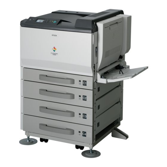
EPSON AcuLaser C9200N Revision D 1.1 Product Specifications Item Specification Noise Printing 52 dB AcuLaser C9200N is a PDL model of a color page printer utilizing laser and Standby 40 dB electrophotographic technologies. Storage and Temperature and Temperature: 0 ~ 35 °C... - Page 13 EPSON AcuLaser C9200N Revision D EXTERNAL VIEW AND PART NAMES Table 1-1. Part Names Table 1-2. Part Names Name Name Name Name Control Panel MP Tray Exhaust filter AC inlet Output Tray Paper Indicator Left side cover Service connector Cover B...
- Page 14 EPSON AcuLaser C9200N Revision D Table 1-3. Part Names Name Name Name Toner Cartridge (Yellow) Photoconductor unit (Black) Power switch Toner Cartridge (Magenta) Photoconductor unit (Cyan) Cover H Toner Cartridge (Cyan) Photoconductor unit (Magenta) Paper path G Toner Cartridge (Black)
- Page 15 EPSON AcuLaser C9200N Revision D DIMENSIONS AND WEIGHT The following figure shows the dimensions and weight of the printer. NOTE 1 : Manufacturing tolerance is ±5 mm in dimensions and ±0.5 kg in weight. 2 : Consumables are not included in the weight of the main unit.
- Page 16 EPSON AcuLaser C9200N Revision D INSTALLATION SPACE REQUIREMENTS The following figure shows the dimensions of the space required around the printer. Be sure to provide the space for installation, operation, and maintenance. 300 mm 200 mm 450 mm 100 mm...
-
Page 17: Paper Specifications
Plain paper / Recycled paper / Thick paper A3F, A3, A4, A5, B4, B5, Letter, LGL, B, GLG, GLT, EXE, F4 64 ~ 256 g/m * : Plain Paper: FX-P (64g/m ), Epson color laser paper (82g/m PRODUCT DESCRIPTION Product Specifications Confidential Downloaded from www.Manualslib.com... - Page 18 EPSON AcuLaser C9200N Revision D UNSUITABLE PAPERS The following types of paper should not be used, otherwise decreased print quality, paper misfeeds, or damage to the printer may occur. Specially-treated papers, such as carbon-backed, non-carbon, heat-sensitive, pressure-sensitive, or acid paper...
- Page 19 EPSON AcuLaser C9200N Revision D PRINTABLE AREA ENVELOPE ORIENTATION Maximum print area (Printing is guaranteed) Envelope Size Monarch, COM-#10, DL, C5, C6 Area excluding 4.2 mm margins on all four edges Feeding (For A3F, all areas except 2 mm from the left and right edges) Direction ↑...
-
Page 20: Replacement Parts
Name Life *1: Calculated on FX-P paper (64 g/m2) Fusing Unit 120,000 pages *2: Calculated on EPSON color laser paper (82 g/m2) Transfer belt unit 120,000 pages 2nd transfer roller (Included in the Transfer belt unit) 120,000 pages Maintenance Unit (Feed roller for MP tray and Standard cassette) -
Page 21: Controller Specifications
EPSON AcuLaser C9200N Revision D 1.1.4 Controller Specifications EXTERNAL INTERFACES Standard USB interface USB 2.0HS Device Interface BASIC SPECIFICATIONS Service connector (USB 2.0HS Host Interface) 32bit RISC CPU Parallel interface IEEE1284 compliant Enhanced Technology NPGI, PGI, CRIT, RIT Ethernet interface... -
Page 22: List Of Printer Messages
EPSON AcuLaser C9200N Revision D 1.2 List of Printer Messages Table 1-6. List of Printer Messages Class Printer Status Error LED status The following table shows the printer’s LEDs indications in each printer status. Form Feed The meanings of the symbols used in the table are as follows. - Page 23 EPSON AcuLaser C9200N Revision D Table 1-6. List of Printer Messages Table 1-6. List of Printer Messages Class Printer Status Error LED status Class Printer Status Error LED status Reserve Job Canceled Service Req Cffff All flashing CompactFlash Full Service Req Eggg...
- Page 24 EPSON AcuLaser C9200N Revision D Table 1-6. List of Printer Messages Note : Messages in the table are sorted in the order descending priorities. The message shown at top of the table has the highest priority. Class Printer Status Error LED status...
-
Page 25: Error Message And Troubleshooting
EPSON AcuLaser C9200N Revision D 1.2.1 Error Message and Troubleshooting Table 1-7. Error Message and Troubleshooting Message Explanation Remedy Table 1-7. Error Message and Troubleshooting 1. Replace the photoconductor Message Explanation Remedy unit of the specified color with a normal one. -
Page 26: Error Led Status
EPSON AcuLaser C9200N Revision D Table 1-7. Error Message and Troubleshooting Table 1-7. Error Message and Troubleshooting Message Explanation Remedy Message Explanation Remedy Error LED flashing Contact Service and replace Printing has stopped because the paper feed roller. After Replace with a new... - Page 27 EPSON AcuLaser C9200N Revision D Table 1-7. Error Message and Troubleshooting Message Explanation Remedy The installed CompactFlash cover F cover B cannot be used on this printer or it is a CompactFlash of less than 4 GB, or "No" is selected when Turn off the printer, remove "Format Required"...
-
Page 28: Warning Message And Troubleshooting
ESC/Page-Color driver or reserve jobs etc. cannot be saved. Printing with the ESC/Page- Confidential). Image Optimum EPSON PCL driver Color driver or EPSON PCL Set the priority of the driver The user attempted registration driver Delete registered forms. Or, data compression method... -
Page 29: Correct Time Using Time Setting
EPSON AcuLaser C9200N Revision D Table 1-8. Warning Message and Troubleshooting Table 1-8. Warning Message and Troubleshooting Message Explanation Remedy Message Explanation Remedy The printer has not been turned on This message is cancelled by Set the date and time again for 10 days or longer and the one of the following. -
Page 30: Needed Soon
EPSON AcuLaser C9200N Revision D Table 1-8. Warning Message and Troubleshooting Table 1-8. Warning Message and Troubleshooting Message Explanation Remedy Message Explanation Remedy This message is cancelled by This message is cancelled by Message warning that the paper one of the following. -
Page 31: Operating Principles
C H A P T E R OPERATING PRINCIPLES Confidential Downloaded from www.Manualslib.com manuals search engine... -
Page 32: Print Process
EPSON AcuLaser C9200N Revision D 2.1 Print Process DrumBk DrumC DrumM DrumY This printer is a "Full color page printer" that uses the principle of 1.Charging 1.Charging 1.Charging 1.Charging electrophotographic recording. Each YMCK color (yellow, magenta, cyan, black) has its own special drum (Photoconductor (PC) drum) and developer 2.Exposure... -
Page 33: Operating Principle Of Main Unit Mechanism
EPSON AcuLaser C9200N Revision D 2.2 Operating Principle of Main Unit Mechanism 2.2.1 Center cross section Fusing Unit 12. Photoconductor Unit/Y [18] [19] [17] Transfer Belt Unit 13. Photoconductor Unit/M [16] 2nd Transfer Roller 14. Photoconductor Unit/C MP tray 15. Photoconductor Unit/K... - Page 34 EPSON AcuLaser C9200N Revision D PAPER PATH Normally, papers are supplied from 2 bins. MP tray (100 papers) and Standard cassette (250 papers). 5 bins of paper supply can be available by setting maximum three optional cassette (500 papers). A Paper supplied from each Tray is transported to the Vertical Transport then an image is transferred in the 2nd Transfer Roller and fused in the Fusing Unit.
-
Page 35: Parts Layout Drawing
EPSON AcuLaser C9200N Revision D 2.2.2 Parts layout drawing ENGINE SECTION [12] [11] [10] [10] 4039F5C502DA 4039F5C501DA [1] Fusing Drive Motor (M4) [7] Cooling Fan Motor/1 (M12) [1] IDC/Registration Sensor/2 (SE2) [6] Controller Board (PWB-P) [2] Main Motor (M1) [8] Toner Supply Motor Y/M (M6) - Page 36 EPSON AcuLaser C9200N Revision D [10] [13] [12] [11] [10] 4039F5C503DA 4039F5C504DA [1] Developing Clutch/K (CL4) [8] Waste Toner Full Sensor (PC8) [1] Right Door Switch (S5) [6] Front Door Switch/2 (S4) [2] Exit Sensor (PC2) [9] Color PC Drive Main Sensor (PC17)
- Page 37 EPSON AcuLaser C9200N Revision D STANDARD CASSETTE [11] [10] 4038T2C111AA 4039T2C113AA 4038T2C026DB [1] Registration Roller Sensor (PC1) [7] Standard Cassette CD Paper Size Sensor (PC9) [2] Standard Cassette Feed Roller [8] Standard Cassette Separation Roller [3] Standard Cassette Separation Roller...
-
Page 38: Ph Unit
EPSON AcuLaser C9200N Revision D 2.2.3 PH Unit 2.2.3.2 Operation 2.2.3.1 Composition OUTLINE 4 types of the PH Unit are used for exposure process. The surface of the Photo Conductor is irradiated with a laser light and an electrostatic latent image is thereby formed. - Page 39 EPSON AcuLaser C9200N Revision D LASER SHUTTER MECHANISM LASER EMISSION AREA Main scan direction (CD) There is a shutter mechanism provided to prevent the PH from being contaminated with foreign matter such as dust when the front cover is opened, The print start position is determined by the start signal for main scan or prevent the emission laser from leaking outside for any reason.
- Page 40 EPSON AcuLaser C9200N Revision D REGISTRATION CONTROL (COLOR SHIFT CORRECTION) SYSTEM SKEW CONTROL MECHANISM In a tandem engine, in which an independent image reproduction process is When the PH Unit is mounted on the main body installation plate, image provided for each of the four different colors of toner. Incorrect color distortion (skew) occurs due to mounting error.
-
Page 41: Photoconductor Unit Section (Pu Section)
EPSON AcuLaser C9200N Revision D 2.2.4 Photoconductor Unit section (PU section) 2.2.4.2 Drive Main Motor (M1) 2.2.4.1 Composition Developing Clutch/K (CL4) Color PC Drum Motor (M2) Color Developing Motor (M3) 4038T2C010AA Photoconductor Unit/Y, M, C 4039T2C107AA Figure 2-12. Drive Overview... - Page 42 EPSON AcuLaser C9200N Revision D 2.2.4.3 Operation When life is reached PU Life is detected by the PU Life counter value. PU LIFE CONTROL When the PU Life counter value is reached to the near life value, the warning message "Photocon xxxx Needed Soon" is displayed.
-
Page 43: Photo Conductor Section
EPSON AcuLaser C9200N Revision D 2.2.5 Photo Conductor section 2.2.5.2 Drive 2.2.5.1 Composition PC DRUM DRIVE MECHANISM Two independent PC Drum Motors (for color and monochrome) are used for the drive mechanism. The Color PC Drum Motor drives the PC Drums/Y, M, and C, while the Main Motor drives the PC Drum/K. -
Page 44: Charge Corona Section
EPSON AcuLaser C9200N Revision D 2.2.6 Charge Corona section 2.2.6.1 Composition Grid Mesh 4039T2C108AA Comb Electrode Cleaning Blade Comb Electrode/Y, M, C, K Grid Mesh 4038T2C027AA Figure 2-16. Composition OPERATING PRINCIPLES Operating Principle of Main Unit Mechanism Confidential Downloaded from www.Manualslib.com... - Page 45 EPSON AcuLaser C9200N Revision D 2.2.6.2 Operation CLEANING/MAIN ERASE MECHANISM PC DRUM CHARGE CORONA ON/OFF CONTROL The Cleaning Blade is pressed up against the surface of the PC Drum, scraping residual toner off the surface (forward blade system). The grid voltage (Vg) applied to the Grid Mesh is controlled through the image Toner, which has been scraped off the surface of the PC Drum, is fed by the Toner stabilization control.
-
Page 46: Developing Section
EPSON AcuLaser C9200N Revision D 2.2.7 Developing section Main Motor (M1) 2.2.7.1 Composition Developing Clutch/K (CL4) Color PC Drum Motor (M2) PC Drum/K Developing Roller Color Developing Motor (M3) PC Drum/Y Supply/Agitating/ Conveying Screws 4039T2C107AA Figure 2-19. Composition 2 Doctor Blade... - Page 47 EPSON AcuLaser C9200N Revision D 2.2.7.2 Drive 2.2.7.3 Operation DEVELOPING DRIVE CONTROL Main Motor (M1) Developing Clutch/K (CL4) Toner Collecting Screw Main Motor (M1) Color PC Drum Motor (M2) Color PC Drum Motor (M2) PC Drum/K Color Developing Motor (M3)
- Page 48 EPSON AcuLaser C9200N Revision D DEVELOPER FLOW Toner Supplied from Hopper Toner supplied from the rear end of the Developing Unit is fed to the lower screw. It is then fed to the front of the unit, while being mixed with developer and electrically charged by the Supply/Agitating/Conveying Screws.
- Page 49 EPSON AcuLaser C9200N Revision D DEVELOPING BIAS The developing bias voltage (Vdc) is applied to the Developing Roller so that an adequate amount of toner is attracted onto the surface of the PC Pressure Plate Developing Bias Terminal Drum. (Main Body Side) During development, Vdc of DC(-) + is applied so that Toner can be attracted PC Drum easily.
- Page 50 EPSON AcuLaser C9200N Revision D DEVELOPMENT SYSTEM TCR SENSOR CONTROL The TCR Sensor detects toner-to-carrier ratio (T/C) of the developer. In the The machine employs the two-component non-contact development system to Mechanical Control Board, the amount of the toner supplied to the achieve even finer reproduction.
-
Page 51: Toner Supply Section
EPSON AcuLaser C9200N Revision D 2.2.8 Toner Supply section 2.2.8.1 Composition Toner Supply Toner Supply Drive Section/K Drive Section/M Toner Supply Drive Section/Y Toner Supply Drive Section/C 4038T2C004AA 4039T2C109AA Agitating Blade/K Toner Cartridge/K Agitating Blade/Y, M, C 4038T2C014AA 4038T2C015AA Toner Cartridge/K... - Page 52 EPSON AcuLaser C9200N Revision D 2.2.8.2 Drive 2.2.8.3 Operation Toner Supply Motor C/K (M7) TONER REPLENISHING MECHANISM/CONTROL Toner replenishing mechanism A single Toner Supply Motor is turned either forward or backward to supply toner of two different colors (Toner Supply Motor for K and C, and Toner Supply Motor for Y and M).
- Page 53 EPSON AcuLaser C9200N Revision D TONER CARTRIDGE LIFE CONTROL SHUTTER MECHANISM Toner Cartridge detection/New unit detection timing To prevent toner from being spilled when the Toner Cartridge is removed from the machine, there is a shutter mechanism provided. When the Toner Cartridge Detection is controlled by confirming the data of each unit with access is installed in the machine, the shutter opens.
-
Page 54: Transfer Corona Section
EPSON AcuLaser C9200N Revision D 2.2.9 Transfer Corona section 2.2.9.1 Composition 1ST IMAGE TRANSFER SECTION Fusing Motor (M4) 4038T2C105AA 4039T2C110AA Pressure Cam 1st Image Transfer Pressure/ Retraction Clutch (CL3) Retraction Roller 1st Image Transfer Roller/M 1st Image Transfer Roller/K 1st Image Transfer... - Page 55 EPSON AcuLaser C9200N Revision D 2ND IMAGE TRANSFER SECTION 2nd Transfer Roller Temperature/Humidity Sensor 4038T2C117AA (SE3) 4039T2C11 AA 4038T2C152AA IDC/Registration Sensor /2 (SE2) IDC/Registration Sensor /1 (SE1) 2nd Transfer Roller Shutter 2nd Image Transfer Pressure Position Sensor (PC7) IDC/Registration Sensor /2 (SE2)
- Page 56 EPSON AcuLaser C9200N Revision D 2.2.9.2 Drive 2ND IMAGE TRANSFER SECTION 2nd Transfer Roller 1ST IMAGE TRANSFER SECTION 2nd Image Transfer Pressure Position Sensor (PC7) Shutter Transfer Belt Pressure Lever Main Motor (M1) IDC/Registration Sensor/2 (SE2) 2nd Image Transfer Pressure/...
- Page 57 EPSON AcuLaser C9200N Revision D 2.2.9.3 Operation Turn the 1st Image Transfer Pressure/Retraction Clutch (CL3) OFF. The Cam will stop rotating and the siding plate will stop. The 1st Image Transfer Roller (Y, M, and C) will stay being pressed.
- Page 58 EPSON AcuLaser C9200N Revision D Operation timing Pressure position changing mechanism To extend the service life of the PC Drum/Y, M, C, the pressure Start Key ON Paper Moves Past 2nd Transfer Roller position of the 1st Image Transfer Roller is changed between the monochrome mode and the color mode.
- Page 59 EPSON AcuLaser C9200N Revision D 2ND TRANSFER ROLLER PRESSURE MECHANISM The 2nd Transfer Roller has the Pressure/Retraction mechanism which presses to and retracts from the Transfer Belt so the patterns made on the Transfer Belt except by printing (such as detection pattern during Image Stabilization) will 2nd Image Transfer not affect the 2nd Transfer Roller.
- Page 60 EPSON AcuLaser C9200N Revision D IDC SENSOR SHUTTER MECHANISM Shutter is closed Shutter is open Image The IDC Sensor can be contaminated with toner since it is located under transfer the Transfer Belt. There is a shutter mechanism provided for the sensor to...
- Page 61 EPSON AcuLaser C9200N Revision D AUTO TRANSFER VOLTAGE CONTROL REVERSING CONTROL OF THE TRANSFER BELT To optimize image transfer output, the machine is provided with auto transfer Paper dust or toner between the Transfer Belt and the edge of the Cleaning voltage control.
- Page 62 EPSON AcuLaser C9200N Revision D 2ND TRANSFER ROLLER CLEANING CHARGE NEUTRALIZATION AND SEPARATION OF PAPER In order to remove the remaining toner on the 2nd Transfer Roller, DC In order to remove the residual potential on the paper with the 2nd Image...
-
Page 63: Toner Collecting Section
EPSON AcuLaser C9200N Revision D 2.2.10 Toner Collecting section 2.2.10.1 Composition PU Toner Collecting Screw Transfer Belt Toner Collecting Screw Waste Toner Collector 4039T2C11 AA 4038T2C023DA Waste Toner Full Sensor (PC8) Waste Toner Collector Waste Toner Conveyance Screw 4038T2C110AA 4038T2C024DA Figure 2-44. - Page 64 EPSON AcuLaser C9200N Revision D 2.2.10.2 Drive 2.2.10.3 Operation TONER COLLECTING MECHANISM Main Motor (M1) Toner collected by the Cleaning Blade of the Transfer Belt and waste toner in each of the Photoconductor Units are conveyed by the corresponding Toner Collecting Screws to the Waste Toner Collector.
- Page 65 EPSON AcuLaser C9200N Revision D WASTE TONER NEAR-FULL/FULL DETECTION CONTROL Waste Toner Detection Mechanism To prevent false detection, an Agitation Screw is mounted in the Waste Toner Collector so that the waste toner is accumulated in the bottle evenly. The Waste Toner Full Sensor (PC8) detects the area where the visor A mounted on the shaft of the Toner Conveying Screw overlaps with the visor B.
-
Page 66: Paper Feed Section (Standard Cassette)
EPSON AcuLaser C9200N Revision D 2.2.11 Paper feed section (Standard Cassette) 2.2.11.1 Composition Std. cassette Device Std. cassette Paper Feed Clutch (CL2) Detection Sensor (PC12) Std. cassette Paper Near-Empty Sensor Std. cassette Paper Empty Sensor (PC10) (PC11) Std. cassette Feed Roller Std. - Page 67 EPSON AcuLaser C9200N Revision D 2.2.11.2 Drive PAPER NEAR-EMPTY/PAPER EMPTY DETECTION When the Standard cassette Paper Near-empty Sensor is blocked, a Main Motor (M1) corresponding warning display is given on the control panel. The Standard cassette Paper Empty Sensor detects a paper empty condition.
- Page 68 EPSON AcuLaser C9200N Revision D PAPER SIZE DETECTION CONTROL Paper Size Board (PWB-I) Paper width/length are detected to determine the paper size from their combination. Table 2-1. Paper size detection control (Standard Cassette) Paper Size Board (PWB-I) CD Paper Size Sensor (PC9)
-
Page 69: Bypass Section (Mp Tray)
EPSON AcuLaser C9200N Revision D 2.2.12 Bypass section (MP tray) 2.2.12.1 Composition MP tray Feed Roller (Bypass) Paper Lifting Plate MP tray Paper Empty Sensor (PC13) MP tray Separation Roller 4038T2C181AA 4039T2C114AA MP tray Paper Empty Sensor (PC13) Paper Side Plate... - Page 70 EPSON AcuLaser C9200N Revision D 2.2.12.2 Drive 2.2.12.3 Operation MP tray Paper Feed Clutch (CL5) PAPER TAKE-UP CONTROL Start Key ON Move to Standby Position Main Motor (M1) MP tray Paper Pick-up Solenoid (SL2) MP tray Lift-up Sensor (PC14) MP tray Paper Feed Clutch (CL5)
- Page 71 EPSON AcuLaser C9200N Revision D PAPER LIFTING MOTION CONTROL Registration Roller It turns the MP tray Pick-Up Solenoid (SL2) ON when the MP tray paper feed is started. The Lifting Cam will rotate to move the Paper Lifting plate up to the feeding position.
-
Page 72: Registration Roller Section
EPSON AcuLaser C9200N Revision D 2.2.13 Registration Roller section 2.2.13.3 Operation 2.2.13.1 Composition REGISTRATION ROLLER CONTROL Registration Roller The followings are controlled. The paper will create a loop between the Feed Roller and the Registration Roller when the paper is being conveyed in order to correct the skew. - Page 73 EPSON AcuLaser C9200N Revision D OHP DETECTION DECELERATION CONTROL OHP Sensor (PC4) checks to prevent printing on the paper other than OHP. It controls the timing the paper reaches to the Registration Roller Sensor (PC1). OHP detection will be performed before paper made the loop at the The Vertical Transport Motor (Vertical Transport Roller) for each tray will Registration Roller.
-
Page 74: Fusing Section
EPSON AcuLaser C9200N Revision D 2.2.14 Fusing section Heating Roller Thermistor/1 (TH1) Heating Roller Thermistor/2 (TH3) Heating Roller Thermistor/3 (TH4) 2.2.14.1 Composition Fusing Pressure Roller Fusing Pressure Roller Thermistor /1 (TH2) Thermistor /1 (TH2) 4038T2C153AA 4038T2C154AA Heating Roller Thermostat (TS1) - Page 75 EPSON AcuLaser C9200N Revision D 2.2.14.2 Drive Fusing Loop Control By creating a paper loop, the speed difference between the fusing and Fusing Drive Motor (M4) paper conveyance at 2nd transfer part will be adjusted. It prevents the double transferred image or brush effect.
- Page 76 EPSON AcuLaser C9200N Revision D Heating Roller Thermistor HEATER LAMP CONSTRUCTION Table 2-5. Heating Roller Thermistor Construction Three heater lamps are controlled to be turned ON/OFF so the temperature of Name Symbol Function the Heating Roller and the Fusing Pressure Roller will stay appropriate to The main thermistor which detects the temperature at completely fuse the image.
- Page 77 EPSON AcuLaser C9200N Revision D THERMOSTAT CONSTRUCTION Leaving the printer for 30 days or more with the Release lever placed in the normal position will deform the pressing part of The Fusing Drive Roller has two thermostats. (One on the Heating Roller and one on Fusing Roller.
- Page 78 EPSON AcuLaser C9200N Revision D • Close the Fusing cover when switching the position from Paper jam release to FUSING ROLLER SMALL AMOUNT ROTATION CONTROL the normal. Closing the Fusing cover will return the Release lever to the normal position.
- Page 79 EPSON AcuLaser C9200N Revision D PAPER WINDING DETECTION CONTROL With the roller fusing type Fusing Unit, paper jam may cause the paper to wind itself to the Fusing Roller. This Winding Detection control monitors the paper to detect when it winds itself to the roller lightly so that it can be removed easily.
- Page 80 EPSON AcuLaser C9200N Revision D FUSING TEMPERATURE CONTROL TEMPERATURE CONTROL IN THE LOW-POWER MODE When with Plain paper, A4 paper (horizontal), single-side 5 sheets, or when It adjusts the temperature by turning the controlled temperature down to reduce above the specified temperature inside the printer with the Main Power Switch the power consumption in standby.
-
Page 81: Paper Exit Section
EPSON AcuLaser C9200N Revision D 2.2.15 Paper exit section 2.2.15.2 Drive 2.2.15.1 Composition Fusing Drive Motor (M4) Paper Exit Roller/1 4039T2C125AA Paper Exit Roller 4039T2C127AA Figure 2-74. Drive overview 4039T2C120AA Paper Exit Roller Charge Neutralizing Brush Exit Sensor 4038T2C192AA Figure 2-73. Composition... -
Page 82: Image Stabilization Control
EPSON AcuLaser C9200N Revision D 2.2.16 Image stabilization control 2.2.16.2 Operation timing Table 2-11. Image stabilization control Stabilizes printed images by adjusting developing bias potential and laser intensity. Also, to prevent color misalignment, control the registration Mode Operation timing correction. -
Page 83: Life Management
EPSON AcuLaser C9200N Revision D 2.2.17 Life management The following table shows the information about the life of consumable products and periodic replacement parts. Panel display continued Parts attributed Image New unit detection Type Unit Status Life detection Solution Dictate Unit... - Page 84 EPSON AcuLaser C9200N Revision D Panel display continued Parts attributed Image New unit detection Type Unit Status Life detection Solution Dictate Unit Error (Reset counter) life quality Message printing Periodic Fusing Unit Near- Condition becomes Near-Empty when any of the...
-
Page 85: Operating Principle Of Option Mechanism
EPSON AcuLaser C9200N Revision D 2.3 Operating principle of Option mechanism Paper Near-Empty Sensor (PC1-PC) 2.3.1 Optional Cassette Lift-up Motor (M3-PC) Vertical Transport Motor (M2-PC) Paper Feed Motor (M1-PC) 2.3.1.1 Composition Device Detection Sensor (PC2-PC) Paper Take-up Sensor (PC9-PC) Feed Roller... - Page 86 EPSON AcuLaser C9200N Revision D 2.3.1.2 Drive PAPER SUPPLY LEVEL DETECTION CONTROL Paper Feed Motor (M1-PC) Paper supply level is indicated in the window of the Cassette Front Cover. Paper Feed Roller (Only for the Optional Cassette) Lift-up Motor When the Paper Lifting Plate goes up, in conjunction with its position, the...
- Page 87 EPSON AcuLaser C9200N Revision D Table 2-12. Paper size detection control (Optional Cassette) Optional Cassette Paper Size Board (PWB-I) Optional Cassette Optional Cassette Paper Size Board (PWB-I) Paper Size CD Size Sensor/1 CD Size Sensor/2 (PC4-PC) (PC3-PC) Guide 4036ma2043c1 Figure 2-80. Paper size detection control...
- Page 88 EPSON AcuLaser C9200N Revision D PAPER LIFTING MOTION CONTROL When Tray is slid in During a print cycle When the Lift-Up Sensor (PC7-PC) of the Optional Cassette is When the amount of paper decreases as the Unit keeps printing, the...
-
Page 89: Duplex Unit
EPSON AcuLaser C9200N Revision D 2.3.2 Duplex Unit 2.3.2.1 Composition Switchback section Switchback to Main Body Paper is fed into the main body again Transport section 4066T1J500DA 4066T2C514DA Figure 2-84. Paper Feed Path Figure 2-83. Composition OPERATING PRINCIPLES Operating principle of Option mechanism... - Page 90 EPSON AcuLaser C9200N Revision D 2.3.2.2 Drive TRANSPORT DRIVE Duplex Control Board Duplex Unit Transport Roller 1 SWITCHBACK DRIVE (PWB-A DU) Duplex Unit Switchback Motor (M1 DU) Main Body Duplex Unit Transport Roller 2 Paper Exit Roller/1 Duplex Unit Transport...
- Page 91 EPSON AcuLaser C9200N Revision D 2.3.2.3 Operation Paper Exit Roller drive coupling mechanism When the Duplex Unit is mounted, the tip of the Duplex Unit Lever raises the Idle Lever to cut off the drive from the main body (Fusing Rollers) and SWITCHBACK MECHANISM the Paper Exit Roller is driven by the Switchback Motor.
- Page 92 EPSON AcuLaser C9200N Revision D TRANSPORT CONTROL The main body carries out the second print cycle to produce the print image of the first page of the original on Rotation speed of the Duplex Unit Transport Motor is controlled by the signals the other side of the 1-sided print.
- Page 93 EPSON AcuLaser C9200N Revision D The Main Body produces the print image of the first page 16. While feeding the second 2-sided print out, the Main Body of the original on the first 1-sided print that has been fed produces the print image of the 8th page of the original on through the Duplex Unit.
-
Page 94: Chapter 1Product Description 2.4.1 Fan Control
EPSON AcuLaser C9200N Revision D 2.4 Other Control 2.4.1.2 Function Table 2-13. Function 2.4.1 Fan Control Motor Name Control Conditions Power Supply It exhausts the accumulated heat inside the unit in order to prevent 2.4.1.1 Construction Cooling Fan Motor/1 temperature from increasing at DC power supply part and the controller (M8) part. - Page 95 EPSON AcuLaser C9200N Revision D 2.4.2 Engine Section Parts Operated When the Main Voltage Connected Parts Power Switch is Turned ON AC Power Heater Lamps Supply When the Main Power Switch is turned ON, the Mechanical Control Board Fan Motors, Solenoids, Clutches, Erase Lamp, Polygon Motor, 2nd detects it and sends a control signal to the DC Power Supply.
- Page 96 C H A P T E R TROUBLESHOOTING Confidential Downloaded from www.Manualslib.com manuals search engine...
-
Page 97: Overview
EPSON AcuLaser C9200N Revision D 3.1 Overview 3.1.2 Preliminary Check Before starting troubleshooting, make sure that the following conditions are all met. For efficient troubleshooting, verify the condition of the trouble carefully, and refer to the troubleshooting procedures given in this chapter, the operating principles (chapter The power supply voltage must be within the specification limits. -
Page 98: Precautions In Performing Troubleshooting Work
EPSON AcuLaser C9200N Revision D 3.1.3 Precautions in Performing Troubleshooting Work 3.1.4 Troubleshooting Flowchart Be sure to unplug the POWER CORD before starting troubleshooting work unless instructed to plug it. Start Never touch any live parts unnecessarily when the power is on. -
Page 99: Jam Display
EPSON AcuLaser C9200N Revision D 3.2 Jam Display 3.2.1 Checking a paper jam type and jammed location WHEN A PAPER JAM ERROR MESSAGE IS DISPLAYED ON THE CONTROL PANEL. Find out the jammed location according to the message on the Control Panel, and perform the related troubleshooting. - Page 100 EPSON AcuLaser C9200N Revision D WHEN A PAPER JAM ERROR MESSAGE IS NOT DISPLAYED ON THE CONTROL PANEL. Print the Error Log Sheet and find out a jam type and the jammed location referring to jam code on the sheet. The jam code is expressed in 8-digit hexadecimal and LSB is added at the end of code.
-
Page 101: Sensor Layout
EPSON AcuLaser C9200N Revision D 3.2.2 Sensor layout [10] Exit Sensor Duplex Unit Transport Sensor 1 PC1 DU Duplex Unit Transport Sensor 2 PC2 DU Registration Roller Sensor OHP Sensor Vertical Transport Sensor (Optional Cassette 1) PC8-PC Paper Take-Up Sensor (Optional Cassette 1) -
Page 102: Solution
EPSON AcuLaser C9200N Revision D 3.2.3 Solution MISFEED AT FUSING/EXIT SECTION (A, B, H) INITIAL CHECK ITEMS When a paper misfeed occurs, first make checks of the following initial check items Detection Timing Table 3-1. Initial Check Items Table 3-2. Detection Timing... - Page 103 EPSON AcuLaser C9200N Revision D MISFEED AT 2ND IMAGE TRANSFER SECTION (A) Action Detection Timing Table 3-5. Action Table 3-4. Detection Timing Relevant Electrical Parts Type Description Detection of The leading edge of the paper does not block the Exit Sensor (PC2) even...
- Page 104 EPSON AcuLaser C9200N Revision D MISFEED AT MP TRAY PAPER FEED SECTION (A, G) MISFEED AT CASSETTE 1 PAPER FEED SECTION (A, G) Detection Timing Detection Timing Table 3-6. Detection Timing Table 3-8. Detection Timing Type Description Type Description Detection of...
- Page 105 EPSON AcuLaser C9200N Revision D MISFEED AT OPTIONAL CASSETTE PAPER FEED, OPTIONAL CASSETTE VERTICAL TRANSPORT SECTION (A, G, E2, E3, E4) Action Detection Timing Table 3-11. Action Table 3-10. Detection Timing Relevant Electrical Parts Type Description Paper Take-Up Sensor (PC9-PC)
- Page 106 EPSON AcuLaser C9200N Revision D MISFEED AT DUPLEX TRANSPORT SECTION (DUPLEX OPTION) (D, A) JAM AT DUPLEX PRE-REGISTRATION SECTION (DUPLEX UNIT) (D, A, Detection Timing Detection Timing Table 3-12. Detection Timing Table 3-14. Detection Timing Type Description Type Description Detection of...
-
Page 107: Service Call Error
EPSON AcuLaser C9200N Revision D 3.3 Service Call Error 3.3.1 Error code The CPU performs a self-diagnostics function. If a malfunction is detected, an error code is displayed on the Control Panel. ERROR CODE LIST Engine-related Error Table 3-16. Error Code List... - Page 108 EPSON AcuLaser C9200N Revision D Table 3-16. Error Code List Code Item Detection Timing Reference The temperature of the Heating Roller Thermistor/1 (TH1) is lower than a given level of degree for 1 second or more uninterruptedly during Ready mode, Low Power mode or printing.
- Page 109 EPSON AcuLaser C9200N Revision D Table 3-16. Error Code List Code Item Detection Timing Reference E406 Mixture ratio of the toner and carrier in the developing machine is lower than the specified value. p.117 Abnormally low toner density detected Black TCR Sensor E407 Abnormally high toner density detected Black TCR Sensor Mixture ratio of the toner and carrier in the developing machine is higher than the specified value.
- Page 110 EPSON AcuLaser C9200N Revision D Table 3-16. Error Code List Code Item Detection Timing Reference E611 An abnormal average value is detected while performing the first image transfer ATVC of black. p.123 1st Image Transfer ATVC (K) failure E612 An abnormal average value is detected while performing the second image transfer ATVC.
- Page 111 EPSON AcuLaser C9200N Revision D Table 3-16. Error Code List Code Item Detection Timing Reference The Lift-Up Sensor is not blocked even after the lapse of a given period of time after the lifting motion has been E702 Standard cassette Elevator failure started.
- Page 112 EPSON AcuLaser C9200N Revision D Controller Related Error Table 3-17. Error Code List Sort code “C” is displayed as “D” depending on the module C H E C K P O I N T Sort Error Code Description Reference that detects errors on the hardware. In this case, read “D” as “C”...
-
Page 113: Solution To Engine-Related Error
EPSON AcuLaser C9200N Revision D 3.3.2 Solution to Engine-Related Error E110: LASER MALFUNCTION (CYAN) E100: POLYGON MOTOR/C FAILURE TO TURN E111: LASER MALFUNCTION (MAGENTA) E101: POLYGON MOTOR/M FAILURE TO TURN E112: LASER MALFUNCTION (YELLOW) E102: POLYGON MOTOR/Y FAILURE TO TURN... - Page 114 EPSON AcuLaser C9200N Revision D E200: TRANSFER BELT SEPARATION E210: 2ND TRANSFER ROLLER SEPARATION Relevant Electrical Parts Relevant Electrical Parts 1st Image Transfer Pressure/Retraction Mechanical Control Board (PWB-M) Right Door Position Sensor (PC6) Main Motor (M1) 1st Image Transfer Pressure/Retraction...
- Page 115 EPSON AcuLaser C9200N Revision D E300: ABNORMALLY LOW HEATING ROLLER TEMPERATURE E310: FUSING UNIT NEW ARTICLE RELEASE E301: ABNORMALLY LOW FUSING PRESSURE ROLLER Relevant Electrical Parts TEMPERATURE Fusing Unit Mechanical Control Board (PWB-M) E302: ABNORMALLY HIGH HEATING ROLLER TEMPERATURE Connection Diagram...
- Page 116 EPSON AcuLaser C9200N Revision D E400: ABNORMALLY LOW TONER DENSITY DETECTED CYAN E401: ABNORMALLY HIGH TONER DENSITY DETECTED CYAN TCR SENSOR TCR SENSOR E402: ABNORMALLY LOW TONER DENSITY DETECTED E403: ABNORMALLY HIGH TONER DENSITY DETECTED MAGENTA TCR SENSOR MAGENTA TCR SENSOR...
- Page 117 EPSON AcuLaser C9200N Revision D E406: ABNORMALLY LOW TONER DENSITY DETECTED BLACK TCR E407: ABNORMALLY HIGH TONER DENSITY DETECTED BLACK TCR SENSOR SENSOR Relevant Electrical Parts Relevant Electrical Parts Photoconductor Unit /K Mechanical Control Board (PWB-M) Photoconductor Unit /K Controller Board (PWB-P)
- Page 118 EPSON AcuLaser C9200N Revision D E500: MAIN MOTOR'S FAILURE TO TURN E501: MAIN MOTOR TURNING AT ABNORMAL TIMING Relevant Electrical Parts Relevant Electrical Parts Main Motor (M1) Main Motor (M1) DC Power Supply (PU1) DC Power Supply (PU1) Mechanical Control Board (PWB-M)
- Page 119 EPSON AcuLaser C9200N Revision D E511: COLOR PC DRUM MOTOR'S TURNING AT ABNORMAL TIMING E520: COLOR DEVELOPING MOTOR'S FAILURE TO TURN Relevant Electrical Parts Relevant Electrical Parts Color PC Drum Motor (M2) Mechanical Control Board (PWB-M) Color Developing Motor (M3)
- Page 120 EPSON AcuLaser C9200N Revision D E521: COLOR DEVELOPING MOTOR'S TURNING AT ABNORMAL E551: COOLING FAN MOTOR/1'S FAILURE TO TURN TIMING Relevant Electrical Parts Relevant Electrical Parts Cooling Fan Motor/1 (M12) Mechanical Control Board (PWB-M) Color Developing Motor (M3) Mechanical Control Board (PWB-M)
- Page 121 EPSON AcuLaser C9200N Revision D E553: FUSING COOLING FAN MOTOR /2'S FAILURE TO TURN E555: POWER SUPPLY COOLING FAN MOTOR'S FAILURE TO TURN Relevant Electrical Parts Relevant Electrical Parts Fusing Cooling Fan Motor/2(M11) Mechanical Control Board (PWB-M) Power Supply Cooling Fan Motor/1 (M8)
- Page 122 EPSON AcuLaser C9200N Revision D E600: CYAN TCR SENSOR ADJUSTMENT FAILURE E603: BLACK TCR SENSOR ADJUSTMENT FAILURE E601: MAGENTA TCR SENSOR ADJUSTMENT FAILURE Relevant Electrical Parts E602: YELLOW TCR SENSOR ADJUSTMENT FAILURE Photoconductor Unit /K Mechanical Control Board (PWB-M) Toner Supply Motor C/K (M7)
- Page 123 EPSON AcuLaser C9200N Revision D E610: 1ST IMAGE TRANSFER ATVC (COLOR) FAILURE E612: 2ND IMAGE TRANSFER ATVC FAILURE Relevant Electrical Parts Relevant Electrical Parts Transfer Belt Unit Transfer Belt Unit High Voltage Unit High Voltage Unit Transfer Roller 2nd Transfer Roller...
- Page 124 EPSON AcuLaser C9200N Revision D E620: COLOR PC DRUM SENSOR MALFUNCTION E621: BLACK PC DRUM SENSOR MALFUNCTION Relevant Electrical Parts Relevant Electrical Parts Transport Drive Assy Transport Drive Assy Harness Harness Mechanical Control Board (PWB-M) Mechanical Control Board (PWB-M) Connection Diagram...
- Page 125 EPSON AcuLaser C9200N Revision D E630: IDC SENSOR (FRONT) FAILURE E631: IDC SENSOR (BACK) FAILURE Relevant Electrical Parts Relevant Electrical Parts IDC Sensor IDC Sensor Connection Diagram Connection Diagram Step Action Step Action Location Location Control Signal Control Signal (electrical parts)
- Page 126 EPSON AcuLaser C9200N Revision D E640: COLOR SHIFT TEST PATTERN FAILURE E641: COLOR SHIFT ADJUST FAILURE Relevant Electrical Parts Relevant Electrical Parts Transfer Belt Unit Photoconductor Unit PH Unit (displacement) IDC Sensor PH Unit Transfer Belt Unit Connection Diagram Connection Diagram...
- Page 127 EPSON AcuLaser C9200N Revision D E701: MP TRAY RISE DESCENT ERROR E702: STANDARD CASSETTE ELEVATOR FAILURE E703: OPTIONAL CASSETTE1 ELEVATOR FAILURE Relevant Electrical Parts E704: OPTIONAL CASSETTE2 ELEVATOR FAILURE MP tray Lift-up Sensor (PC14) Control Board (PWB-Z-PC) Vertical Transport Motor (M2-PC)
- Page 128 EPSON AcuLaser C9200N Revision D E900: FLASH ROM WRITE ERROR E998: ENGINE COMMUNICATION ERROR Relevant Electrical Parts Relevant Electrical Parts Mechanical Control Board (PWB-M) Controller Board (PWB-P) Mechanical Control Board (PWB-M) Connection Diagram Connection Diagram Step Action Step Action Location...
-
Page 129: Controller Related Error
EPSON AcuLaser C9200N Revision D 3.3.3 Controller Related Error Check that the DIMM is connected to the controller board securely and correctly. When a controller related error occurs, make sure to check the initial check items listed Check that the printer is not in electrically noisy environments. - Page 130 EPSON AcuLaser C9200N Revision D Table 3-18. Failed Parts List Error-causing hard ware (or factor) Mechanical Sort Error Code Description Controller Std. RAM Opt. RAM Video I/F Code DIMM Control Noise, etc. Board DIMM DIMM Cable Board √ 1123 ROM checksum error (program) √...
-
Page 131: Other Errors
EPSON AcuLaser C9200N Revision D 3.3.4 Other Errors Details for troubleshooting on error message “Photocon Trouble uuuu”. Cause Adhesion toner on transfer belt is outside a proper range while image stabilizing control Abnormal access between Photoconductor unit IC chip and Printer... - Page 132 EPSON AcuLaser C9200N Revision D Table 3-19. Troubleshooting Step Remedy and Check Point Check the connection status and stain on high voltage point between Photoconductor unit and High voltage unit. Figure 3-1. High voltage point on Photoconductor unit Correct connection...
- Page 133 EPSON AcuLaser C9200N Revision D Table 3-19. Troubleshooting Step Remedy and Check Point 1. "Photocon Trouble uuuu" - single color appear Exchange abnormal color PH unit for normal color PH unit. If it is caused by PH unit, Exchange PH unit.
-
Page 134: Power Supply Trouble
EPSON AcuLaser C9200N Revision D 3.4 Power supply trouble 3.4.2 Control panel indicators do not light 3.4.1 Machine is not energized at all (PU1 operation check) Relevant Electrical Parts Controller Board (PWB-P) Relevant Electrical Parts DC Power Supply (PU1) Control Panel (PWB-OP) -
Page 135: Fusing Heaters Do Not Operate
EPSON AcuLaser C9200N Revision D 3.4.3 Fusing Heaters do not operate 3.4.4 Power is not supplied to option Optional Paper Cabinet Unit Relevant Electrical Parts Primary Interlock Switch (S2) Location DC Power Supply (PU1) Fusing Unit Step Check Item (electrical... -
Page 136: Image Quality Problem
EPSON AcuLaser C9200N Revision D 3.5 Image quality problem 3.5.2 Image Trouble List Table 3-20. Image Trouble List When an image quality problem occurs, first go through the Initial Check Items and, if the cause is yet to be identified, go to troubleshootings per image trouble. - Page 137 EPSON AcuLaser C9200N Revision D Table 3-20. Image Trouble List Table 3-20. Image Trouble List Sample Symptom Reference Sample Symptom Reference <Monocolor> <Monocolor> p.144 p.140 uneven density in main scan direction blank print, black print 4036fs4046c0 4036fs4047c0 4036fs4038c0 4036fs4039c0 ABCDE ABCDE <Monocolor>...
- Page 138 EPSON AcuLaser C9200N Revision D Table 3-20. Image Trouble List Table 3-20. Image Trouble List Sample Symptom Reference Sample Symptom Reference <4-Color> <4-Color > p.148 p.154 uneven density in main scan direction brush effect, blurred image 4036fs4046c0 4036fs4047c0 4036fs4061c0 4036fs4031c0...
-
Page 139: Solution
EPSON AcuLaser C9200N Revision D 3.5.3 Solution <MONOCOLOR> WHITE LINES IN MAIN SCAN DIRECTION, WHITE BANDS IN MAIN SCAN DIRECTION, COLORED LINES IN MAIN SCAN DIRECTION, <MONOCOLOR> COLORED BANDS IN MAIN SCAN DIRECTION WHITE LINES IN SUB SCAN DIRECTION, WHITE BANDS IN SUB SCAN DIRECTION, COLORED LINES COLORED BANDS IN SUB SCAN A. -
Page 140: Uneven Density In Main Scan Direction
EPSON AcuLaser C9200N Revision D <MONOCOLOR> <MONOCOLOR> UNEVEN DENSITY IN SUB SCAN DIRECTION UNEVEN DENSITY IN MAIN SCAN DIRECTION A. Typical Faulty Images A. Typical Faulty Images 4036fs4043c0 4036fs4044c0 4036fs4045c0 4036fs4046c0 4036fs4047c0 B. Troubleshooting Procedure B. Troubleshooting Procedure Step Section... -
Page 141: Low Image Density (Decrease Of Id)
EPSON AcuLaser C9200N Revision D <MONOCOLOR> Step Section Check Item Result Action LOW IMAGE DENSITY (DECREASE OF ID) The problem has been Change Photoconductor Unit. → eliminated through the checks Change Controller Board. A. Typical Faulty Images of steps up to 9. -
Page 142: Gradation Reproduction Failure
EPSON AcuLaser C9200N Revision D <MONOCOLOR> <MONOCOLOR> GRADATION REPRODUCTION FAILURE FOGGY BACKGROUND A. Typical Faulty Images A. Typical Faulty Images ABCD ABCD ABCD ABCD ABCD 4036fs4048c0 4036fs4049c0 4036fs4030c0 B. Troubleshooting Procedure B. Troubleshooting Procedure Step Section Check Item Result Action... -
Page 143: Monocolor> Void Areas, White Spots
EPSON AcuLaser C9200N Revision D <MONOCOLOR> <MONOCOLOR> VOID AREAS, WHITE SPOTS COLORED SPOTS A. Typical Faulty Images A. Typical Faulty Images Void areas White spots Colored spots 4036fs4052c0 4036fs4051c0 4036fs4050c0 B. Troubleshooting Procedure B. Troubleshooting Procedure Step Section Check Item... -
Page 144: Monocolor> Blurred Image
EPSON AcuLaser C9200N Revision D <MONOCOLOR> <MONOCOLOR> BLURRED IMAGE BLANK PRINT, BLACK PRINT A. Typical Faulty Images A. Typical Faulty Images Blurred image Blank print Black print 4036fs4031c0 4036fs4038c0 4036fs4039c0 B. Troubleshooting Procedure B. Troubleshooting Procedure Step Section Check Item... -
Page 145: Monocolor> Uneven Image
EPSON AcuLaser C9200N Revision D <MONOCOLOR> UNEVEN IMAGE A. Typical Faulty Images 4138fs4507c0 B. Troubleshooting Procedure Step Section Check Item Result Action Toner Cartridge The Toner Cartridge of every Re-install it. color is surely installed. PH Unit PH Unit is surely installed. -
Page 146: White Lines In Sub Scan Direction
EPSON AcuLaser C9200N Revision D <4-COLOR> Step Section Check Item Result Action WHITE LINES IN SUB SCAN DIRECTION, WHITE BANDS IN SUB SCAN The problem has been Change Controller Board. DIRECTION, COLORED LINES IN SUB SCAN DIRECTION, AND eliminated through the checks (p.198) -
Page 147: White Lines In Main Scan Direction
EPSON AcuLaser C9200N Revision D <4-COLOR> Step Section Check Item Result Action WHITE LINES IN MAIN SCAN DIRECTION, WHITE BANDS IN MAIN Fusing Unit Fusing Entrance Guide Plate Clean. SCAN DIRECTION, COLORED LINES IN MAIN SCAN DIRECTION, AND is dirty or damaged. -
Page 148: Uneven Density In Sub Scan Direction
EPSON AcuLaser C9200N Revision D <4-COLOR> <4-COLOR> UNEVEN DENSITY IN SUB SCAN DIRECTION UNEVEN DENSITY IN MAIN SCAN DIRECTION A. Typical Faulty Images A. Typical Faulty Images 4036fs4043c0 4036fs4044c0 4036fs4046c0 4036fs4047c0 B. Troubleshooting Procedure B. Troubleshooting Procedure Step Section Check Item... -
Page 149: Low Image Density (Decrease Of Id)
EPSON AcuLaser C9200N Revision D <4-COLOR> Step Section Check Item Result Action LOW IMAGE DENSITY (DECREASE OF ID) The problem has been Change Transfer Belt Unit. eliminated through the checks (p.162) A. Typical Faulty Images → of steps up to 6. -
Page 150: Poor Color Reproduction
EPSON AcuLaser C9200N Revision D <4-COLOR> Step Section Check Item Result Action POOR COLOR REPRODUCTION The problem has been Change Transfer Belt Unit. eliminated through the checks (p.162) A. Typical Faulty Images → of steps up to 6. Change Controller Board. -
Page 151: Incorrect Color Image Registration
EPSON AcuLaser C9200N Revision D <4-COLOR> INCORRECT COLOR IMAGE REGISTRATION A. Typical Faulty Images 4036fs4032c0 B. Troubleshooting Procedure Step Section Check Item Result Action Machine Vibration is given to the Turn off the Main Power condition machine after main power Switch and turn it on again switch has been turned ON. -
Page 152: Void Areas, White Spots
EPSON AcuLaser C9200N Revision D <4-COLOR> Step Section Check Item Result Action VOID AREAS, WHITE SPOTS The problem has been Change Transfer Belt Unit. eliminated through the checks (p.162) A. Typical Faulty Images of steps up to 8. Void area... -
Page 153: 4-Color> Colored Spots
EPSON AcuLaser C9200N Revision D <4-COLOR> <4-COLOR> COLORED SPOTS POOR FUSING PERFORMANCE, OFFSET A. Typical Faulty Images A. Typical Faulty Images Poor fusing Offset performance 4036fs4052c0 4036fs4059c0 4036fs4060c0 B. Troubleshooting Procedure B. Troubleshooting Procedure Step Section Check Item Result Action... -
Page 154: Brush Effect, Blurred Image
EPSON AcuLaser C9200N Revision D <4-COLOR> <4-COLOR> BRUSH EFFECT, BLURRED IMAGE BACK MARKING A. Typical Faulty Images A. Typical Faulty Images Brush effect Blurred image 4036fs4061c0 4036fs4031c0 4036fs4062c0 4036fs4063c0 B. Troubleshooting Procedure B. Troubleshooting Procedure Step Section Check Item Result... -
Page 155: 4-Color> Uneven Image
EPSON AcuLaser C9200N Revision D <4-COLOR> <MONOCOLOR> OR <4-COLOR> UNEVEN IMAGE IMAGE TROUBLES THAT APPEAR AT REGULAR INTERVALS When an image trouble occurred at the certain pitch, some rollers at the printing A. Typical Faulty Images process or the paper conveying system in the engine have something wrong. Perform efficient trouble shooting by checking the appropriate roller, based on circumferential length (interval) for each roller listed in the following table. -
Page 156: Disassembly And Assembly
C H A P T E R DISASSEMBLY AND ASSEMBLY Confidential Downloaded from www.Manualslib.com manuals search engine... -
Page 157: Preliminary Check
EPSON AcuLaser C9200N Revision D 4.1 Preliminary Check 4.1.2 Parts/Units that Should Not be Disassembled Do not disassemble the following parts or units. Doing so can result in malfunction of 4.1.1 Tool List the printer. Consumables / After Service Parts The tools listed below are required for disassembling the printer. -
Page 158: How To Read This Chapter
EPSON AcuLaser C9200N Revision D 4.1.3 How to Read this Chapter PAGE CONFIGURATION Opening page Main page Guide Part Name Final Procedure Guide to indicate the Shows part to be The pink Guide indicates that the Location procedural steps. disassembled or operation to... - Page 159 EPSON AcuLaser C9200N Revision D 3. Go to main pages, find the columns that has the “Guide” character on the PROCEDURE upper left corner, and perform the procedure described in the columns in 1. Find the part/unit you want to remove in the table.
-
Page 160: List Of Disassembly/Reassembly Parts/Units
EPSON AcuLaser C9200N Revision D 4.2 List of Disassembly/Reassembly Parts/Units Table 4-1. Main Unit Section Parts/Unit Ref. Table 4-1. Main Unit Multi Bypass Unit P. 210 PH Unit P. 175 Section Parts/Unit Ref. Transfer Drive Assy P. 230 Toner Cartridge (+ Odor Filter) P. - Page 161 EPSON AcuLaser C9200N Revision D Table 4-2. Optional Cassette Unit Parts/Unit Ref. Optional Cassette P. 275 Rear Right Cover + Rear Left Cover P. 275 Right Rear Cover P. 275 Control Board (PWB-Z-PC) P. 279 Paper Size Board (PWB-I-PC) P. 279 Lift-Up Motor (M3-PC) P.
-
Page 162: Main Unit Disassembly/Reassembly
EPSON AcuLaser C9200N Revision D 4.3 Main Unit Disassembly/Reassembly Exhaust Filter Photoconductor Unit 4.3.1 Group 1 CONTENT Parts/Units to be Disassembled Guide Front Cover Front Door Transfer Belt Unit Photoconductor Unit Fusing Unit Waste Toner Collector + Exhaust Filter Waste Toner Collector... - Page 163 EPSON AcuLaser C9200N Revision D DISASSEMBLY FLOWCHART Start Front Door (P. 164) Transfer Belt Unit (P. 164) Photoconductor Unit (P. 166) Fusing Unit (P. 166) Waste Toner Collector (P. 168) + Exhaust Filter DISASSEMBLY AND ASSEMBLY Main Unit Disassembly/Reassembly Confidential Downloaded from www.Manualslib.com...
- Page 164 EPSON AcuLaser C9200N Revision D Front Door Transfer Belt Unit 4039F2C005DA 4038F2C038DB The Transfer Belt Unit is included in "Transfer Kit" as a service part. Additionally, the C H E C K P O I N T 2nd Image Transfer Roller, Ozone filter, and Dust Filter are also included in "Transfer Kit".
- Page 165 EPSON AcuLaser C9200N Revision D 4039F2C006DA Matched Not Matched 3. Hold the both sides and lift it to take out the Transfer Belt Unit [3] a little. Insert the Transfer Belt Unit into the Main Unit completely and make sure the Drive Gear of the Transfer Belt Unit matches with that of the Main Unit.
- Page 166 EPSON AcuLaser C9200N Revision D Photoconductor Unit Fusing Unit 4039F2C010DA Don't burn the Photoconductor Unit. Toner remnants may spatter and cause fire. And 4039F2C011DA It may result in burns. Before replacing the Fusing Unit, ensure that it has had time to cool down.
- Page 167 EPSON AcuLaser C9200N Revision D 4039F2C012DA 4039F2C014DA 4039F2C013DA 5. Remove the Screw [4], and remove the Connector protective cover [5]. 7. Open the Right Door. 6. Disconnect two Connectors [6]. 8. Open the Fusing Unit Cover. 9. Remove two Screws [7], and remove the Fusing unit [8].
- Page 168 EPSON AcuLaser C9200N Revision D Waste Toner Collector + Exhaust Filter Don't burn the used Waste Toner Collector. Toner may spatter and cause fire. And It 3. Remove the Exhaust Filter from the top face of the printer. may result in burns.
-
Page 169: Group 2
EPSON AcuLaser C9200N Revision D 4.3.2 Group 2 Dust Filter CONTENT Parts/Units to be Disassembled Guide 2nd Transfer Unit Ozone Filter Dust Filter Feed Roller (Standard Cassette) Separation Roller (Standard Cassette) Ozone Filter Feed Roller Separation Roller 2nd Transfer Unit... - Page 170 EPSON AcuLaser C9200N Revision D DISASSEMBLY FLOWCHART Start 2nd Transfer Unit (P. 171) Ozone Filter (P. 171) Dust Filter (P. 172) Feed Roller (Std. Cassette) (P. 172) Separation Roller (Std. Cassette) (P. 173) DISASSEMBLY AND ASSEMBLY Main Unit Disassembly/Reassembly Confidential Downloaded from www.Manualslib.com...
- Page 171 EPSON AcuLaser C9200N Revision D 2nd Transfer Unit Ozone Filter The 2nd transfer roller is included in the Transfer unit, and the 2nd transfer roller The ozone filter is included in the Transfer unit, and the filter should be replaced with...
- Page 172 EPSON AcuLaser C9200N Revision D Dust Filter Feed Roller (Standard Cassette) The dust filter is included in the Transfer unit, and the filter should be replaced with The separation roller should be replaced, whenever the feed roller is replaced. C H E C K...
- Page 173 EPSON AcuLaser C9200N Revision D Separation Roller (Standard Cassette) 4038F2C002DB 5. Snap off the C-clip [4], one collar [5] and remove the Feed Roller [6]. C H E C K The pickup roller should be replaced, whenever the separation roller is replaced.
- Page 174 EPSON AcuLaser C9200N Revision D 4038F2C003DB 4037F2C509DA 3. Take off the rubber stopper [3], shaft [4], spring [5], and guide plate [6] to remove the Separation Roller fixing bracket assy [7]. 4. Snap off the E-ring [8] and the Separation Roller [9].
-
Page 175: Group 3
EPSON AcuLaser C9200N Revision D 4.3.3 Group 3 Front Cover CONTENT Parts/Units to be Disassembled Guide Toner Cartridge (+ Odor Filter) Front Cover PH Interface Board (PWB-D) PH Unit Odor Filter Toner Cartridge PH Interface Board (PWB-D) PH Unit DISASSEMBLY AND ASSEMBLY... - Page 176 EPSON AcuLaser C9200N Revision D DISASSEMBLY FLOWCHART Start Toner Cartridge (+ Odor Filter) Transfer Belt Unit (P. 177) (P. 184) Photoconductor Unit PH Unit PH Interface Board (PWB-D) (P. 178) (P. 188) (P. 185) Waste Toner Collector (P. 178) + Exhaust Filter Rear Left Cover + Front Left Cover (P.
- Page 177 EPSON AcuLaser C9200N Revision D Toner Cartridge (+ Odor Filter) Don't burn the Toner Cartridge. Toner may spatter and cause fire. And It may result in burns. Don't touch the inside printer which is not specified while replacing. It may result Replace the Odor Filter when replacing black (K) Toner Cartridge.
- Page 178 EPSON AcuLaser C9200N Revision D Photoconductor Unit Waste Toner Collector + Exhaust Filter Don't burn the Photoconductor Unit. Toner remnants may spatter and cause fire. And Don't burn the used Waste Toner Collector. Toner may spatter and cause fire. And It It may result in burns.
- Page 179 EPSON AcuLaser C9200N Revision D Rear Left Cover + Front Left Cover 3. Remove the Exhaust Filter from the top face of the printer. 1. Remove two Screws [2], and remove the Rear Left Cover [3]. 2. Open the Front Door [1].
- Page 180 EPSON AcuLaser C9200N Revision D Rear Right Cover + Rear Cover Exit Tray 4039F2C019DA 1. Open the Right Door [1]. 1. Open the Upper Fusing Cover [2]. 2. Remove three Screws [2], and remove the Right Rear Cover [3]. 2. Remove two Claws [3], and remove the Upper Fusing Cover [2].
- Page 181 EPSON AcuLaser C9200N Revision D Front Door 4038F2C038DB 3. Remove two Screws [5], and remove the Exit Sensor Holder [6]. 4038F2C039DA 4. Remove three Screws [7], and remove the Exit Tray [8]. 1. Open the Front Door. 2. Remove the Screw [1] each to remove the Right and Left Stoppers [2].
- Page 182 EPSON AcuLaser C9200N Revision D Front Cover 4038F2C051DA 3. Release two Hooks [4] and remove the Guide [5] installed in the insertion slot of the Toner Cartridge (K). 4038F2C052DA Don't use too much force when releasing the Hooks of the Guide because they break 1.
- Page 183 EPSON AcuLaser C9200N Revision D 4038F2C053DA 4038F2C055DA 4. Disconnect two Connectors [6]. 6. Remove six Claws [8] and remove the Front Cover [9]. 5. Remove four Screws [7]. DISASSEMBLY AND ASSEMBLY Main Unit Disassembly/Reassembly Confidential Downloaded from www.Manualslib.com manuals search engine...
- Page 184 EPSON AcuLaser C9200N Revision D Transfer Belt Unit 4039F2C006DA 4039F2C005DA The Transfer Belt Unit is included in "Transfer Kit" as a service part. Additionally, the C H E C K P O I N T 2nd Image Transfer Roller, Ozone filter, and Dust Filter are also included in "Transfer Kit".
- Page 185 EPSON AcuLaser C9200N Revision D PH Interface Board (PWB-D) 4038F2C097DA Matched Not Matched 1. Pull out the Paper Cassette 1. 2. Remove two Screws [1], and remove the Front Right Cover [2]. Insert the Transfer Belt Unit into the Main Unit completely and make sure the Drive Gear of the Transfer Belt Unit matches with that of the Main Unit.
- Page 186 EPSON AcuLaser C9200N Revision D 4038F2C098DA When connecting the Connector to the Photoconductor Unit Contact Assy, check the color of Connector and connect it to corresponding that of the Imaging Unit. 4038F2C099DA 3. Remove seven Screws [3], and remove the Right Door Switch Assy [4].
- Page 187 EPSON AcuLaser C9200N Revision D [10] [11] 4038F2C100DA [10] 4038F2C102DB 7. Remove two Screws [9] and six tabs [10], and remove the PH Interface Board [11]. 5. Remove eight Screws [7] and remove four Photoconductor Unit Roll Assy [8] of each color.
- Page 188 EPSON AcuLaser C9200N Revision D PH Unit 4038F2C106DA When replacing the PH Unit, replace four units at the same time. When installing the Photoconductor Unit Guide rail, insert its end correctly to the Even when the single Unit needs to be replaced, replace four units.
- Page 189 EPSON AcuLaser C9200N Revision D ○ × 4038F2C107DA 4038F2C109DA When removing the Stopper, use care so that both ends of the Stopper will not open 4038F2C108DB but stay parallel as shown in the figure above. Keep using the Stopper after once stretched out may cause uneven pitch or other image troubles.
- Page 190 EPSON AcuLaser C9200N Revision D [10] [11] 4038F2C110DA 4037F2C113DB [12] [14] [13] 4037F2C111DB 5. Remove the PH Unit (Black) according to the following procedure. 1. Move the front side of the PH Unit to left a little, and remove the Boss [9] from the locating 4037F2C114DA hole [10].
- Page 191 EPSON AcuLaser C9200N Revision D ○ × 4038F2C116DA 4038F2C115DA 4. Reinstall the Stopper [7]. 5. Reinstall the Gear [8]. 6. Connect the Connector and the Flat Cable. When reinstalling the Stopper, use care so that both ends of the Stopper will not open but stay parallel as shown in the figure above.
- Page 192 EPSON AcuLaser C9200N Revision D [10] 4038F2C117DA 7. Install the Photoconductor Unit Guide Rail [9]. Make sure that the two Claws [10] at rear end of the rail are fit in the locating hole on the Main Unit. 8. Reinstall the Transfer Belt Unit.
-
Page 193: Group 4
EPSON AcuLaser C9200N Revision D 4.3.4 Group 4 DISASSEMBLY FLOWCHART CONTENT Start Parts/Units to be Disassembled Guide Rear Left Cover + Front Left Cover Rear Left Cover + Front Left Cover (P. 194) Exit Tray Upper Cover + Control Panel Right Rear Cover + Rear Cove (P. - Page 194 EPSON AcuLaser C9200N Revision D Rear Left Cover + Front Left Cover Right Rear Cover + Rear Cover 1. Remove two Screws [2], and remove the Rear Left Cover [3]. 1. Open the Right Door [1]. 2. Open the Front Door [1].
- Page 195 EPSON AcuLaser C9200N Revision D Exit Tray 4039F2C019DA 1. Open the Upper Fusing Cover [2]. 3. Remove two Screws [5], and remove the Exit Sensor Holder [6]. 2. Remove two Claws [3], and remove the Upper Fusing Cover [2]. 4. Remove three Screws [7], and remove the Exit Tray [8].
- Page 196 EPSON AcuLaser C9200N Revision D Upper Cover + Control Panel 1. Remove four Screws [1]. 2. Remove the Ground terminal [2]. 3. Remove the Connector [3], then remove the Upper Cover [4]. 4. Remove five Screws [5], then remove the Control Panel [6].
- Page 197 EPSON AcuLaser C9200N Revision D DC Power Supply (PU1) 1. Remove nine Screws [1] and the Connector [2], then remove the protective sheet of the DC 2. Remove all the Connectors on the DC Power Supply. Power Supply [3]. 3. Remove eight Screws [4], and remove the DC Power Supply [5].
-
Page 198: Group 5
EPSON AcuLaser C9200N Revision D 4.3.5 Group 5 CONTENT Mechanical Control Board (PWB-M) Parts/Units to be Disassembled Guide Controller Board (PWB-P) RTC Board (PWB-R) Mechanical Control Board (PWB-M) RTC Board (PWB-R) Controller Board (PWB-P) DISASSEMBLY AND ASSEMBLY Main Unit Disassembly/Reassembly... - Page 199 EPSON AcuLaser C9200N Revision D DISASSEMBLY FLOWCHART Start Rear Left Cover + Front Left Cover (P. 200) Controller Board (PWB-P) (P. 200) Exit Tray (P. 201) Controller Board Mounting Bracket (P. 202) RTC Board (PWB-R) Mechanical Control Board (PWB-M) (P. 203) (P.
- Page 200 EPSON AcuLaser C9200N Revision D Rear Left Cover + Front Left Cover Controller Board (PWB-P) 1. Remove two Screws [2], and remove the Rear Left Cover [3]. 1. Remove six Screws [1]. 2. Open the Front Door [1]. 3. Remove two Screws [4], and remove the Front Left Cover [5].
- Page 201 EPSON AcuLaser C9200N Revision D Exit Tray 4039F2C019DA 1. Open the Upper Fusing Cover [2]. 2. Remove two Connectors [2], the Type-B Guide rail [3], and three Harnesses [4]. 2. Remove two Claws [3], and remove the Upper Fusing Cover [2].
- Page 202 EPSON AcuLaser C9200N Revision D Controller Board Mounting Bracket 3. Remove two Screws [5], and remove the Exit Sensor Holder [6]. 4. Remove three Screws [7], and remove the Exit Tray [8]. 1. Remove three Wire Saddles [1], six Screws [6], and four Clamp Cores [3], then remove the Flat Cable Cover.
- Page 203 EPSON AcuLaser C9200N Revision D Mechanical Control Board (PWB-M) 1. Remove all the Connectors and Flat Cables on the Mechanical Control Board. 2. Remove six Screws [8] and remove the Mechanical Control Board [9]. 2. Remove eleven Screws [5] and release the Edge Cover [6], and remove the Controller Board Mounting Bracket [7].
- Page 204 EPSON AcuLaser C9200N Revision D Parameter Chip (IC6) Not Used (CNSKF) 4037F2C061DB Not Used (CNTM) 4037F2C534DA When the Mechanical Control Board (PWB-M) is replaced, relocate the Parameter Chip (IC6). Mount the Parameter Chip (IC6) of old Mechanical Control Board onto the new Mechanical Control Board.
- Page 205 EPSON AcuLaser C9200N Revision D RTC Board (PWB-R) 4039F2C034DA 1. Disconnect the Connector [1], and remove two Screws [2], and remove the RTC Board [3]. DISASSEMBLY AND ASSEMBLY Main Unit Disassembly/Reassembly Confidential Downloaded from www.Manualslib.com manuals search engine...
-
Page 206: Group 6
EPSON AcuLaser C9200N Revision D 4.3.6 Group 6 Paper Width <Base of the Main Unit> Detection Unit CONTENT Parts/Units to be Disassembled Guide Standard Paper Cassette Paper Width Detection Unit DISASSEMBLY FLOWCHART Start Standard Paper Cassette (P. 207) Optional Cassette (P. - Page 207 EPSON AcuLaser C9200N Revision D Standard Paper Cassette 1. Slide out the Standard Paper Cassette [1]. 2. Slide out the Standard Paper Cassette with pressing the Slide Locks [2] at both ends. DISASSEMBLY AND ASSEMBLY Main Unit Disassembly/Reassembly Confidential Downloaded from www.Manualslib.com...
- Page 208 EPSON AcuLaser C9200N Revision D Optional Cassette 1. Slide out the Optional Cassette [1]. 2. Remove the Screw [2] and remove the Stopper [3]. 3. Remove the Optional Cassette with while pressing the Slide Lock [4]. DISASSEMBLY AND ASSEMBLY Main Unit Disassembly/Reassembly...
- Page 209 EPSON AcuLaser C9200N Revision D Paper Width Detection Unit 1. Remove the Paper Width Detection Unit pushing it toward the Right Door, with pushing the 2. Remove two Connectors and release the Harness from the tab of the Paper Width Detection Knob [A] on the upper inside wall of the Tray toward the Right Door.
-
Page 210: Group 7
EPSON AcuLaser C9200N Revision D 4.3.7 Group 7 IDC Sensor/2 (SE2) IDC Sensor/1 (SE1) CONTENT Parts/Units to be Disassembled Guide MP tray Left Cover + MP tray Right Cover + Tray Extension Multi Bypass Unit IDC Sensor/1 (SE1) + IDC Sensor/2 (SE2) - Page 211 EPSON AcuLaser C9200N Revision D DISASSEMBLY FLOWCHART Start MP tray Left Cover + MP tray Right Cover + Tray Extension (P. 212) Multi Bypass Unit (P. 212) Transfer Belt Unit Feed Roller (MP tray) Separation Roller (MP tray) (P. 215) (P.
- Page 212 EPSON AcuLaser C9200N Revision D MP tray Left Cover + MP tray Right Cover Multi Bypass Unit + Tray Extension 4038F2C103DA 4039F2C017DA 1. Remove the Claw [1] and remove the MP tray Left Cover [2]. 1. Disconnect four Connectors [1].
- Page 213 EPSON AcuLaser C9200N Revision D Boss 2. Open the right door. When assembling the Guide again after the Guide has been removed for some reason, insert the Hinge to the position as shown in the figure above. Additionally, when 3. Disengage the boss of the guide [1] to free the guide [1].
- Page 214 EPSON AcuLaser C9200N Revision D Guide 4038F2C105DA Insert the Guide with pushing it down to the Main Unit so that the Guide gets into the Insert the Multi Bypass Unit to the Main Unit after fitting the position of Dowels as lower side of the Main Unit Cover.
- Page 215 EPSON AcuLaser C9200N Revision D Transfer Belt Unit 4039F2C006DA 4039F2C005DA The Transfer Belt Unit is included in "Transfer Kit" as a service part. Additionally, the C H E C K P O I N T 2nd Image Transfer Roller, Ozone filter, and Dust Filter are also included in "Transfer Kit".
- Page 216 EPSON AcuLaser C9200N Revision D IDC Sensor/1 (SE1) + IDC Sensor/2 (SE2) 4038F2C169DA Matched Not Matched 1. Remove the Screw [1], and remove the Plate Spring [2]. Insert the Transfer Belt Unit into the Main Unit completely and make sure the Drive Gear of the Transfer Belt Unit matches with that of the Main Unit.
- Page 217 EPSON AcuLaser C9200N Revision D 4038F2C171DA [12] [10] [11] 5. Remove two Claws [7] of both sides, and remove the Sensor cover [8]. Use care not to miss the spring [9]. 2. Remove the Shoulder Screw [3] and the Screw [4].
- Page 218 EPSON AcuLaser C9200N Revision D Feed Roller (MP tray) [13] 4038F2C004DA 4038F2C173DA 7. Repeat the steps from 5 to 6 and remove the IDC sensor/2 (rear side) [13]. 4038F2C005DA The separation roller should be replaced, whenever the feed roller is replaced.
- Page 219 EPSON AcuLaser C9200N Revision D 4038F2C006DB 4038F2C008DB 4038F2C007DB 3. Snap off the E-ring [4] and remove the Bearing [5]. 5. Remove the Feed Roller [8]. 4. Snap off two C-ring [6], and remove the Bearing [7]. When installing the Feed Roller with a new one, make sure to reset the life counter.
- Page 220 EPSON AcuLaser C9200N Revision D Separation Roller (MP tray) 4038F2C009DA 4038F2C502DA 3. Snap off the C-clip [5], and remove the spring [6] and the guide plate [7]. Remove the Separation Roller [8]. 4038F2C010DA The pickup roller should be replaced, whenever the separation roller is replaced.
-
Page 221: Group 8
EPSON AcuLaser C9200N Revision D 4.3.8 Group 8 Rear Cover Right Rear Cover CONTENT Parts/Units to be Disassembled Guide Right Rear Cover + Rear Cover Standard cassette Paper Size Board (PWB-I) Fusing Drive Motor (M4) Toner Supply Motor C/K (M7) - Page 222 EPSON AcuLaser C9200N Revision D DISASSEMBLY FLOWCHART Start Right Rear Cover + Rear Cover (P. 223) Fusing Drive Motor (M4) Standard cassette Paper Size Toner Supply Motor C/K (M7) Toner Supply Motor Y/M (M6) (P. 224) (P. 225) (P. 225) Board (PWB-I) (P.
- Page 223 EPSON AcuLaser C9200N Revision D Standard cassette Paper Size Board Right Rear Cover + Rear Cover (PWB-I) 4038F2C088DA 1. Open the Right Door [1]. 1. Slide out the Paper Cassette 1. 2. Remove three Screws [2], and remove the Right Rear Cover [3].
- Page 224 EPSON AcuLaser C9200N Revision D Fusing Drive Motor (M4) 4039F2C518DA 4038F2C516DA 1. Remove the Connector [1] and two Screws [2], and remove the Fusing Drive Motor (M4) 3. Remove the Lever [4]. [3]. 4. Remove the Standard cassette Paper Size Board (PWB-I) [5].
- Page 225 EPSON AcuLaser C9200N Revision D Toner Supply Motor C/K (M7) Toner Supply Motor Y/M (M6) 1. Remove the Connector [1] and two Screws [2], and remove the Toner Supply Motor C/K [3]. 1. Remove the Connector [1] and two Screws [2], and remove the Toner Supply Motor Y/M [3].
-
Page 226: Group 9
EPSON AcuLaser C9200N Revision D 4.3.9 Group 9 Main Motor (M1) CONTENT Color PC Drum Motor (M2) Parts/Units to be Disassembled Guide Color Developing Motor (M3) Color Developing Motor (M3) Color PC Drum Motor (M2) Main Motor (M1) DISASSEMBLY AND ASSEMBLY... - Page 227 EPSON AcuLaser C9200N Revision D DISASSEMBLY FLOWCHART Start Right Rear Cover + Rear Cover (P. 228) Main Motor (M1) Color Developing Motor (M3) Color PC Drum Motor (M2) (P. 229) (P. 228) (P. 229) DISASSEMBLY AND ASSEMBLY Main Unit Disassembly/Reassembly...
- Page 228 EPSON AcuLaser C9200N Revision D Right Rear Cover + Rear Cover Color Developing Motor (M3) 4038F2C149DA 1. Open the Right Door [1]. 1. Remove the Connector [1] and four Screws [2], and remove the Color Developing Motor [3]. 2. Remove three Screws [2], and remove the Right Rear Cover [3].
- Page 229 EPSON AcuLaser C9200N Revision D Color PC Drum Motor (M2) Main Motor (M1) 4038F2C150DA 4039F2C517DA 1. Remove the Connector [1] and four Screws [2], and remove the Color PC Drum Motor [3]. 1. Remove the Connector [1] and four Screws [2], and remove the Main Motor [3].
-
Page 230: Group 10
EPSON AcuLaser C9200N Revision D 4.3.10 Group 10 High Voltage Unit (HV1) 1st Image Transfer Pressure/Retraction CONTENT Clutch (CL3) Parts/Units to be Disassembled Guide High Voltage Unit (HV1) Transfer Drive Assy Fusing Drive Assy 1st Image Transfer Pressure/Retraction Clutch (CL3) - Page 231 EPSON AcuLaser C9200N Revision D DISASSEMBLY FLOWCHART Start Right Rear Cover + Rear Cover Rear Left Cover + Front Left Cover (P. 232) (P. 241) High Voltage Unit (HV1) Exit Tray (P. 232) (P. 241) Color Developing Motor (M3) Fusing Drive Assy (P.
- Page 232 EPSON AcuLaser C9200N Revision D Right Rear Cover + Rear Cover High Voltage Unit (HV1) 1. Open the Right Door [1]. 2. Remove three Screws [2], and remove the Right Rear Cover [3]. 3. Remove nine Screws [4], and remove the Rear Cover [5].
- Page 233 EPSON AcuLaser C9200N Revision D Figure 1 Terminal end position M Mark Figure 2 P Mark 4038F2C087DA Make sure following things when installing the High Voltage Unit (HV1). Be cautious not to install the wrong Screw because two types of Screws [2] are Terminal end surely contacts (Refer to Figure 1).
- Page 234 EPSON AcuLaser C9200N Revision D Color Developing Motor (M3) Color PC Drum Motor (M2) 4038F2C149DA 4038F2C150DA 1. Remove the Connector [1] and four Screws [2], and remove the Color Developing Motor 1. Remove the Connector [1] and four Screws [2], and remove the Color PC Drum Motor [3].
- Page 235 EPSON AcuLaser C9200N Revision D Main Motor (M1) Transfer Drive Assy 4039F2C517DA 4038F2C118DA 1. Remove the Connector [1] and four Screws [2], and remove the Main Motor [3]. 1. Remove three Screws [1], and remove the Reinforcement plate [2] of the Right Door and spring [3].
- Page 236 EPSON AcuLaser C9200N Revision D 4038F2C119DA [10] 2. Remove the Shoulder Screw [4]. 3. Remove two Screws [5], and remove the Metal blanking plate [6]. [11] 4038F2C121DA 4. Remove two Screws [7] and remove the Rear Handle Assy Protect Cover [8].
- Page 237 EPSON AcuLaser C9200N Revision D [14] [13] [12] [11] [12] [10] [13] 4038F2C123DA C H E C K [11] P O I N T 4038F2C122DA 6. Remove two Harnesses [12] from four Wire Saddles [11]. 7. Remove eight Screws [13], and remove the Transport Drive Assy [14].
- Page 238 EPSON AcuLaser C9200N Revision D Fusing Unit 4039F2C012DA 4039F2C010DA 4039F2C013DA 4039F2C011DA Before replacing the Fusing Unit, ensure that it has had time to cool down. 5. Remove the Screw [4], and remove the Connector protective cover [5]. 6. Disconnect two Connectors [6].
- Page 239 EPSON AcuLaser C9200N Revision D Transfer Belt Unit 4039F2C005DA 4039F2C014DA The Transfer Belt Unit is included in "Transfer Kit" as a service part. Additionally, the C H E C K P O I N T 2nd Image Transfer Roller, Ozone filter, and Dust Filter are also included in "Transfer Kit".
- Page 240 EPSON AcuLaser C9200N Revision D 4039F2C006DA Matched Not Matched 3. Hold the both sides and lift it to take out the Transfer Belt Unit [3] a little. Insert the Transfer Belt Unit into the Main Unit completely and make sure the Drive Gear of the Transfer Belt Unit matches with that of the Main Unit.
- Page 241 EPSON AcuLaser C9200N Revision D Rear Left Cover + Front Left Cover Exit Tray 4039F2C019DA 1. Remove two Screws [2], and remove the Rear Left Cover [3]. 1. Open the Upper Fusing Cover [2]. 2. Open the Front Door [1].
- Page 242 EPSON AcuLaser C9200N Revision D Fusing Drive Assy 3. Remove two Screws [5], and remove the Exit Sensor Holder [6]. 4. Remove three Screws [7], and remove the Exit Tray [8]. 1. Remove three Screws [1] from rear side of the Main body and remove the Metal Blanking Plate [2].
- Page 243 EPSON AcuLaser C9200N Revision D 4. Remove the Fusing Drive Assy pushing upward [5] the connection part of the Transfer Belt from the right Door side. 2. Remove three Screws [3] from the rear side of the Main body. 3. Release the hook section of the Spring from the groove to the rear side from upper part of Main Unit of the right rear side.
- Page 244 EPSON AcuLaser C9200N Revision D 1st Image Transfer Pressure/Retraction Clutch (CL3) 3. Remove two Screws [4], three E-rings [5] and remove Install Board [6]. 1. Remove two Screws [1] from the Fusing Drive Assy and remove the Fusing Drive Motor [2].
- Page 245 EPSON AcuLaser C9200N Revision D [10] 4. Remove the Gear [7] and then remove the Gear [8]. 5. Remove the 1st Image Transfer Pressure/Retraction Clutch [10] with the Shaft [9]. DISASSEMBLY AND ASSEMBLY Main Unit Disassembly/Reassembly Confidential Downloaded from www.Manualslib.com...
-
Page 246: Group 11
EPSON AcuLaser C9200N Revision D 4.3.11 Group 11 Hopper Drive Assy CONTENT Parts/Units to be Disassembled Guide Hopper Drive Assy Standard Cassette Paper Feed Clutch (CL2) 1st Image Transfer Pressure/Retraction Position Sensor (PC6) Standard cassette Paper Feed Clutch (CL2) 1st Image Transfer Pressure/... - Page 247 EPSON AcuLaser C9200N Revision D DISASSEMBLY FLOWCHART Start Right Rear Cover + Rear Cover (P. 248) High Voltage Unit (HV1) (P. 248) Color Developing Motor (M3) (P. 250) Color PC Drum Motor (M2) (P. 250) Main Motor (M1) (P. 251) Transfer Drive Assy (P.
- Page 248 EPSON AcuLaser C9200N Revision D Right Rear Cover + Rear Cover High Voltage Unit (HV1) 1. Open the Right Door [1]. 2. Remove three Screws [2], and remove the Right Rear Cover [3]. 3. Remove nine Screws [4], and remove the Rear Cover [5].
- Page 249 EPSON AcuLaser C9200N Revision D Figure 1 Terminal end position M Mark Figure 2 P Mark 4038F2C087DA Make sure following things when installing the High Voltage Unit (HV1). Be cautious not to install the wrong Screw because two types of Screws [2] are Terminal end surely contacts (Refer to Figure 1).
- Page 250 EPSON AcuLaser C9200N Revision D Color Developing Motor (M3) Color PC Drum Motor (M2) 4038F2C149DA 4038F2C150DA 1. Remove the Connector [1] and four Screws [2], and remove the Color Developing Motor 1. Remove the Connector [1] and four Screws [2], and remove the Color PC Drum Motor [3].
- Page 251 EPSON AcuLaser C9200N Revision D Main Motor (M1) Transfer Drive Assy 4039F2C517DA 4038F2C118DA 1. Remove the Connector [1] and four Screws [2], and remove the Main Motor [3]. 1. Remove three Screws [1], and remove the Reinforcement plate [2] of the Right Door and spring [3].
- Page 252 EPSON AcuLaser C9200N Revision D 4038F2C119DA [10] 2. Remove the Shoulder Screw [4]. 3. Remove two Screws [5], and remove the Metal blanking plate [6]. [11] 4038F2C121DA 4. Remove two Screws [7] and remove the Rear Handle Assy Protect Cover [8].
- Page 253 EPSON AcuLaser C9200N Revision D [14] [13] [12] [11] [12] [10] [13] 4038F2C123DA C H E C K [11] P O I N T 4038F2C122DA 6. Remove two Harnesses [12] from four Wire Saddles [11]. 7. Remove eight Screws [13], and remove the Transport Drive Assy [14].
- Page 254 EPSON AcuLaser C9200N Revision D Hopper Drive Assy 4038F2C125DA 4038F2C124DB 1. Disconnect seven Connectors [1]. 2. Remove the Harness from four Wire Saddles [2]. DISASSEMBLY AND ASSEMBLY Main Unit Disassembly/Reassembly Confidential Downloaded from www.Manualslib.com manuals search engine...
- Page 255 EPSON AcuLaser C9200N Revision D 4038F2C127DA 4038F2C126DA 3. Remove the Connector from the Cooling Fan Motor [3] and 1st Image Transfer Pressure/ 5. Remove four Screws [7] and two Claws [8], and remove the Hopper Drive Assy [9]. Retraction Position Sensor [4].
- Page 256 EPSON AcuLaser C9200N Revision D Standard Cassette Paper Feed Clutch (CL2) 1. Remove the E-ring [1], three Screws [2] and remove the Standard Cassette Feed Clutch Cover [3]. 2. Remove the E-ring[4] and three Screws [5] and then remove the Standard Cassette Feed Clutch Cover [6].
- Page 257 EPSON AcuLaser C9200N Revision D [14] [10] [12] [11] [13] [12] [11] C H E C K Before Releasing P O I N T [10] After Releasing [15] [16] 4. Remove the Conductive Spring Assy [11] by removing two Hooks [10].
- Page 258 EPSON AcuLaser C9200N Revision D 1st Image Transfer Pressure/Retraction Position Sensor (PC6) [18] [17] 1. Remove the 1st Image Transfer Pressure/Retraction Position Sensor Unit [3] by removing Be cautious following things when installing the Feed Clutch. the Screw [1] and Connector [2].
- Page 259 EPSON AcuLaser C9200N Revision D When removing the 1st Image Transfer Pressure/Retraction Position Sensor, if the Torsion Coil Spring has come off, correctly install it referring to the Figure. After installing the Torsion Coil Spring, check if the Actuator operates normally.
-
Page 260: Group 12
EPSON AcuLaser C9200N Revision D 4.3.12 Group 12 Right Door CONTENT Parts/Units to be Disassembled Guide Right Door Near Empty Assy <Base of the Main Unit> Near Empty Assy DISASSEMBLY AND ASSEMBLY Main Unit Disassembly/Reassembly Confidential Downloaded from www.Manualslib.com manuals search engine... - Page 261 EPSON AcuLaser C9200N Revision D DISASSEMBLY FLOWCHART Start Right Rear Cover + Rear Cover (P. 262) High Voltage Unit (HV1) (P. 262) Standard cassette Front Door (P. 267) (P. 264) Optional Cassette Right Door (P. 268) (P. 264) Near Empty Assy (P.
- Page 262 EPSON AcuLaser C9200N Revision D Right Rear Cover + Rear Cover High Voltage Unit (HV1) 1. Open the Right Door [1]. 2. Remove three Screws [2], and remove the Right Rear Cover [3]. 3. Remove nine Screws [4], and remove the Rear Cover [5].
- Page 263 EPSON AcuLaser C9200N Revision D Figure 1 Terminal end position M Mark Figure 2 P Mark 4038F2C087DA Make sure following things when installing the High Voltage Unit (HV1). Be cautious not to install the wrong Screw because two types of Screws [2] are Terminal end surely contacts (Refer to Figure 1).
- Page 264 EPSON AcuLaser C9200N Revision D Front Door Right Door 4038F2C038DB 4039F2C510DA 1. Open the Right Door. 4038F2C039DA 2. Remove three Screws [1], and remove the Reinforcement plate [2] of the right door and spring [3]. 1. Open the Front Door.
- Page 265 EPSON AcuLaser C9200N Revision D 4039F2C511DA [10] 3. Remove the Shoulder Screw [4]. 4. Remove two Screws [5], and remove the Metal blanking plate [6]. [11] 4039F2C513DA 5. Remove two Screws [7] and remove the Rear Handle Assy Protect Cover [8].
- Page 266 EPSON AcuLaser C9200N Revision D [12] [12] [12] [14] [13] [12] [13] 4039F2C514DA 4039F2C515DA 7. Disconnect four Connectors [12]. 9. Remove two Screws [13], and remove the Front Right Cover [14]. 8. Slide out the Paper Cassette 1. DISASSEMBLY AND ASSEMBLY...
- Page 267 EPSON AcuLaser C9200N Revision D Paper Cassette 1 [15] [17] [16] 4039F2C516DA 1. Slide out the Standard Paper Cassette [1]. 10.Remove the Screw [15], and remove the Shaft [16]. 11.Remove the Right Door [17]. DISASSEMBLY AND ASSEMBLY Main Unit Disassembly/Reassembly...
- Page 268 EPSON AcuLaser C9200N Revision D Optional Cassette 1. Slide out the Optional Cassette [1]. 2. Slide out the Standard Paper Cassette with pressing the Slide Locks [2] at both ends. DISASSEMBLY AND ASSEMBLY Main Unit Disassembly/Reassembly Confidential Downloaded from www.Manualslib.com...
- Page 269 EPSON AcuLaser C9200N Revision D Near Empty Assy 2. Remove the Screw [2] and remove the Stopper [3]. 3. Remove the Optional Cassette with while pressing the Slide Lock [4]. 1. Pick up and remove the Actuator from the front side.
- Page 270 EPSON AcuLaser C9200N Revision D [3] [4] 3. Put the Near Empty Assy [2] through the hole of the Flame bringing down the Near Empty 4. Remove two Connectors and remove the Near Empty Assy. [2] Assy to the rear side from the front side.
-
Page 271: Group 13
EPSON AcuLaser C9200N Revision D 4.3.13 Group 13 Switchback Motor (M1DU) CONTENT Parts/Units to be Disassembled Guide Duplex Unit Duplex Unit Rear Cover Switchback Motor (M1DU) DISASSEMBLY FLOWCHART Duplex Unit Rear Cover Start Duplex Unit (P. 272) Rear Cover (P. 273) Switchback Motor (M1DU) (P. - Page 272 EPSON AcuLaser C9200N Revision D Duplex Unit 4066F2C502DA 4066F2C500DA 4066F2C501DA 3. Open the Duplex Unit Door [4]. 4. Remove two Shoulder screws [5], and remove the Duplex Unit [7] while disabling Hook 1. Release the tab [1], and remove the Connector Cover [2].
- Page 273 EPSON AcuLaser C9200N Revision D Duplex Unit Rear Cover Switchback Motor (M1DU) 1. Remove three Screws [1], remove the Rear Cover [2]. 1. Remove six Screws [1], and remove the Metal blanking plate. DISASSEMBLY AND ASSEMBLY Main Unit Disassembly/Reassembly Confidential Downloaded from www.Manualslib.com...
- Page 274 EPSON AcuLaser C9200N Revision D 2. Remove the Connector [2] and two Screws [3], and remove the Switchback Motor [4]. DISASSEMBLY AND ASSEMBLY Main Unit Disassembly/Reassembly Confidential Downloaded from www.Manualslib.com manuals search engine...
-
Page 275: Group 14
EPSON AcuLaser C9200N Revision D 4.3.14 Group 14 CONTENT Parts/Units to be Disassembled Guide Optional Cassette Rear Right Cover Rear Right Cover + Rear Left Cover Rear Right Cover Rear Left Cover Optional Cassette DISASSEMBLY FLOWCHART Rear Right Cover Start Optional Cassette (P. - Page 276 EPSON AcuLaser C9200N Revision D Optional Cassette 1. Slide out the Optional Cassette [1]. 2. Remove the Screw [2] and remove the Stopper [3]. 3. Remove the Optional Cassette with while pressing the Slide Lock [4]. DISASSEMBLY AND ASSEMBLY Main Unit Disassembly/Reassembly...
- Page 277 EPSON AcuLaser C9200N Revision D Right Rear Cover Rear Right Cover + Rear Left Cover 4039F2C050DA 1. Remove two Screws [1] and remove the Right Rear Cover [2]. 1. Release two Tabs [1], remove the Connector Cover [2]. DISASSEMBLY AND ASSEMBLY...
- Page 278 EPSON AcuLaser C9200N Revision D 4038F2C048DA 2. Remove four Screws [3], and remove the Rear Right Cover [4]. 3. Remove three Screws [5], and remove the Rear Left Cover [6]. DISASSEMBLY AND ASSEMBLY Main Unit Disassembly/Reassembly Confidential Downloaded from www.Manualslib.com...
-
Page 279: Group 15
EPSON AcuLaser C9200N Revision D 4.3.15 Group 15 Lift-Up Motor (M3-PC) CONTENT Control Board (PWB-Z-PC) Parts/Units to be Disassembled Guide Control Board (PWB-Z-PC) Paper Size Board (PWB-I-PC) Lift-Up Motor (M3-PC) Paper Size Board (PWB-I-PC) DISASSEMBLY AND ASSEMBLY Main Unit Disassembly/Reassembly... - Page 280 EPSON AcuLaser C9200N Revision D DISASSEMBLY FLOWCHART Start Rear Right Cover + Rear Left Cover (P. 281) Control Board (PWB-Z-PC) Paper Size Board (PWB-I-PC) Lift-Up Motor (M3-PC) (P. 282) (P. 283) (P. 285) DISASSEMBLY AND ASSEMBLY Main Unit Disassembly/Reassembly Confidential Downloaded from www.Manualslib.com...
- Page 281 EPSON AcuLaser C9200N Revision D Rear Right Cover + Rear Left Cover 4038F2C048DA 1. Release two Tabs [1], remove the Connector Cover [2]. 2. Remove four Screws [3], and remove the Rear Right Cover [4]. 3. Remove three Screws [5], and remove the Rear Left Cover [6].
- Page 282 EPSON AcuLaser C9200N Revision D Control Board (PWB-Z-PC) 4039F2C056DA 4039F2C054DA 4039F2C057DA 4039F2C055DA 3. Remove all the Connectors on the Control Board. 1. Remove the Screw [1], and remove the Metal blanking plate [2]. 4. Remove four Screws [5], and remove the Control Board [6].
- Page 283 EPSON AcuLaser C9200N Revision D Paper Size Board (PWB-I-PC) 4039F2C058DA 4039F2C054DA 1. Remove the Screw [1], and remove the Metal blanking plate [2]. 4067F2C512DA 2. Remove the Harness [4] from the Edge cover [3]. 3. Remove three Screws [5], and remove the Control Board Assy [6].
- Page 284 EPSON AcuLaser C9200N Revision D [10] [11] 4067F2C513DA 4067F2C514DA 4. Remove two Claws [7] and the Connector [8], and remove the Paper Size Board Assy [9]. 5. Remove the Lever [10], and remove the Paper Size Board [11]. Be cautious for working not to deform the Lever parts.
- Page 285 EPSON AcuLaser C9200N Revision D Lift-Up Motor (M3-PC) 4038F2C166DA 4038F2C165DA 1. Slide out the Optional Cassette. 3. Disconnect the Connector [3]. 2. Remove two Screws [1], and remove the Reinforcement plate [2]. 4. Remove three Screws [4], and remove the Lift-Up Motor [5].
-
Page 286: Group 16
EPSON AcuLaser C9200N Revision D 4.3.16 Group 16 CONTENT Vertical Transport Motor (M2-PC) Paper Feed Motor (M1-PC) Parts/Units to be Disassembled Guide Paper Feed Motor (M1-PC) Vertical Transport Motor (M2-PC) DISASSEMBLY FLOWCHART Start Rear Right Cover + Rear Left Cover (P. - Page 287 EPSON AcuLaser C9200N Revision D Rear Right Cover + Rear Left Cover 4038F2C048DA 1. Release two Tabs [1], remove the Connector Cover [2]. 2. Remove four Screws [3], and remove the Rear Right Cover [4]. 3. Remove three Screws [5], and remove the Rear Left Cover [6].
- Page 288 EPSON AcuLaser C9200N Revision D Paper Feed Motor (M1-PC) 4038F2C167DA 4038F2C165DA 1. Slide out the Optional Casset. 3. Remove the Harness of the Motor Assy [4] from five Wire Saddles [3]. 2. Remove two Screws [1], and remove the Reinforcement plate [2].
- Page 289 EPSON AcuLaser C9200N Revision D Vertical Transport Motor (M2-PC) 4038F2C168DA 4038F2C165DA 1. Slide out the Optional Cassette. 5. Remove two Screws [6], and remove the Motor Assy [7]. 2. Remove two Screws [1], and remove the Reinforcement plate [2]. 6. Remove two Screws [8], and remove the Paper Feed Motor [9].
- Page 290 EPSON AcuLaser C9200N Revision D 4038F2C168DA 4038F2C167DA 3. Remove the Harness of the Motor Assy [4] from five Wire Saddles [3]. 4. Disconnect two Connectors [5]. 4038F2C520DA 5. Remove two Screws [6], and remove the Motor Assy [7]. 6. Remove two Screws [8], and remove the Vertical Transport Motor [9].
-
Page 291: Group 17
EPSON AcuLaser C9200N Revision D 4.3.17 Group 17 DISASSEMBLY FLOWCHART CONTENT Start Parts/Units to be Disassembled Guide Vertical Transport Door Vertical Transport Door (P. 292) Separation Roller Installation Plate Assy Feed Roller (Optional Cassette Unit) Separation Roller Installation Plate Assy (P. - Page 292 EPSON AcuLaser C9200N Revision D Vertical Transport Door Separation Roller Installation Plate Assy 4039F2C048DA 1. Slide out the paper cassette. 1. Remove two Screws [1], and remove the jam processing cover [2]. 2. Open the Vertical Transport Door. Make sure the position of the polyester film when installing the jam processing cover.
- Page 293 EPSON AcuLaser C9200N Revision D Separation Roller (Optional Cassette Unit) 4038F2C508DA 4038F2C013DA 4038F2C559DA 1. Remove two C-rings [1] and the shaft [2], and remove the separation roller fixing plate assy 2. Remove two Screws [3] and the Separation Roller Installation Plate Assy [4].
- Page 294 EPSON AcuLaser C9200N Revision D Right Rear Cover Feed Roller (Optional Paper Cassette) 4039F2C051DA 4039F2C050DA 1. Remove two Screws [1] and remove the Right Rear Cover [2]. 4067F2C501DA The separation roller should be replaced, whenever the pickup roller is replaced.
- Page 295 EPSON AcuLaser C9200N Revision D 4067F2C502DA 4067F2C504DA [10] [12] [13] [11] [11] [14] 4067F2C510DA 4067F2C503DA 4067F2C511DA 3. Remove four Screws [4] and remove the pickup roller assy [5]. 5. Remove two Screws [8] and pickup roller cover 9]. 4. Remove two Screws [6] and the installation flame [7] of the separation roller installation 6.
- Page 296 EPSON AcuLaser C9200N Revision D [16] [21] [20] [15] 4067F2C505DA [22] 4067F2C507DA [25] [23] [23] [26] [17] [19] [24] [18] [27] 4067F2C509DA 4067F2C508DA 8. Remove the C-ring [15] and bushing [16]. 10.Remove the C-ring [20] and bushing [21], and remove the shaft assy [22].
-
Page 297: Others
EPSON AcuLaser C9200N Revision D 4.4 Others [1]COOLING FAN MOTOR/2 (M22) The specific disassembling and assembling procedures are not explained, and only points in work are shown. Screw Connector Screw 4039F5C502DA Cooling Fan Motor/2 (M22) p.297 Cooling Fan Motor/1 (M12) p.298... - Page 298 EPSON AcuLaser C9200N Revision D [2]COOLING FAN MOTOR/1 (M12) [4]POWER SUPPLY COOLING FAN MOTOR/1 (M8) Connector Connector Rear Right Turn the side that the label is attached on to the back. Screw Screw Turn the side that the label is attached on to the front.
- Page 299 EPSON AcuLaser C9200N Revision D [5]FUSING COOLING FAN MOTOR/2 (M11) Turn the side that the label Connector is attached on to the back. Screw Top Right Fusing Cooling Fan Motor/2 (M11) DISASSEMBLY AND ASSEMBLY Others Confidential Downloaded from www.Manualslib.com manuals search engine...
- Page 300 EPSON AcuLaser C9200N Revision D [1]WASTE TONER FULL SENSOR (PC8) Waste Toner Full Sensor (PC8) Rear Right Connector 4039F5C503DA Waste Toner Full Sensor (PC8) p.300 Front Door Switch/2 (S4) p.301 Front Door Switch/1 (S3) p.301 Main Power Switch (S1) p.302 Primary Interlock Switch (S2) p.302...
- Page 301 EPSON AcuLaser C9200N Revision D [2]FRONT DOOR SWITCH/2 (S4) [3]FRONT DOOR SWITCH/1 (S3) Front Door Switch/2 (S4) Screw Front Left Front Left Screw Front Door Switch/1 (S3) When installing the Front Door Switch/2 (S4), refer to the following Connector figure and notice the color of the Connector.
- Page 302 EPSON AcuLaser C9200N Revision D [4]MAIN POWER SWITCH (S1) Install the Switch in the following Refer to the below figure, note the color DC Power Supply Connector Hook direction. of the Connector and the color of the Harness. Main Power...
- Page 303 EPSON AcuLaser C9200N Revision D [6]RIGHT DOOR SWITCH (S5) When installing the Right Door Switch, be careful the following points. Be careful not to insert the red and white connectors into the Right Door Switch (S5) incorrect place. Be careful to hook the Actuator to the Spring properly.
- Page 304 EPSON AcuLaser C9200N Revision D [1]DEVELOPING CLUTCH/K (CL4) Developing Clutch/K (CL4) Connector Rear Left Match the Rotation Stopper of the Clutch with the tab of the Main Unit. 4039F5C505DA Developing Clutch/K (CL4) p.304 MP tray Lift-Up Sensor (PC14) p.305 MP tray Paper Feed Clutch (CL5) p.305...
- Page 305 EPSON AcuLaser C9200N Revision D [2]MP TRAY LIFT-UP SENSOR (PC14) [4]MP TRAY PAPER EMPTY SENSOR (PC13) Multi Bypass Unit (Refer to Multi Bypass Unit (Refer to Multi Bypass Unit (p210)) Multi Bypass Unit (p210)) Tray1 Lift-Up Sensor (PC14) Connector [3]MP TRAY PAPER FEED CLUTCH (CL5)
- Page 306 EPSON AcuLaser C9200N Revision D [1]CD PAPER SIZE SENSOR/1 (PC4-PC) Rear Center 4039F5C506DA CD Paper Size Sensor/1 (PC4-PC) CD Paper Size Sensor/1 (PC4-PC) p.306 Set Sensor (PC2-PC) p.307 CD Paper Size Sensor/2 (PC3-PC) p.307 Paper Near-Empty Sensor (PC1-PC) p.308 Door Set Sensor (PC5-PC) p.309...
- Page 307 EPSON AcuLaser C9200N Revision D [2]SET SENSOR (PC2-PC) [3]CD PAPER SIZE SENSOR/2 (PC3-PC) Rear Center Rear Center CD Paper Size Sensor/2 (PC3-PC) Connector Set Sensor (PC2-PC) DISASSEMBLY AND ASSEMBLY Others Confidential Downloaded from www.Manualslib.com manuals search engine...
- Page 308 EPSON AcuLaser C9200N Revision D [4]PAPER NEAR-EMPTY SENSOR (PC1-PC) Rear Center Paper Near-Empty Sensor (PC1-PC) Connector Screw DISASSEMBLY AND ASSEMBLY Others Confidential Downloaded from www.Manualslib.com manuals search engine...
- Page 309 EPSON AcuLaser C9200N Revision D [5]DOOR SET SENSOR (PC5-PC) [6]VERTICAL TRANSPORT SENSOR (PC8-PC) [7]PAPER TAKE-UP SENSOR (PC9-PC) [8]PAPER EMPTY SENSOR (PC6-PC) [9]LIFT-UP SENSOR (PC7-PC) Door Set Sensor (PC5-PC) Vertical Transport Sensor (PC8-PC) Connector Connector Paper Take-Up Sensor (PC9-PC) Lift-Up Sensor...
- Page 310 EPSON AcuLaser C9200N Revision D [1]DUPLEX UNIT DOOR SET SENSOR (PCIDU) 4038F5C512DA Duplex Unit Door Set Sensor Duplex Unit Door Set Sensor (PCIDU) p.309 Duplex Unit Switchback Motor (M2DU) p.311 Duplex Unit Transport Sensor 2 (PC2DU) p.312 Connector Duplex Control Board (PWB-A DU) p.312...
- Page 311 EPSON AcuLaser C9200N Revision D [2]DUPLEX UNIT TRANSPORT MOTOR (M2DU) Duplex Unit Transport Motor Connector Screw (+ Nut) Screw (+ Nut) DISASSEMBLY AND ASSEMBLY Others Confidential Downloaded from www.Manualslib.com manuals search engine...
- Page 312 EPSON AcuLaser C9200N Revision D [3]DUPLEX UNIT TRANSPORT SENSOR 1 (PC1DU) [4]DUPLEX CONTROL BOARD (PWB-A DU) [5]DUPLEX UNIT TRANSPORT SENSOR 2 (PC2DU) Duplex Control Board Screw Duplex Unit Transport Sensor 1 Connector Screw Connector Duplex Unit Transport Sensor 1 DISASSEMBLY AND ASSEMBLY...
- Page 313 C H A P T E R ADJUSTMENT Confidential Downloaded from www.Manualslib.com manuals search engine...
-
Page 314: Adjustment Item
EPSON AcuLaser C9200N Revision D 5.1 Adjustment Item The table below shows the adjustment item (including life counter clear) required when the specified part/unit is fixed or replaced. Part/Unit Timing Item Adjustment Procedure Required Jig & Tool Reference PH unit... -
Page 315: Adjustment
EPSON AcuLaser C9200N Revision D 5.2 Adjustment 5.2.1 Skew Adjustment PURPOSE Adjust the gradient of the PH unit of each color and prevent the image skew from occurring. PROCEDURE After replacing or reinstalling the PH units, start the printer in the maintenance mode. -
Page 316: Mp Tray Mechanical Adjustment
EPSON AcuLaser C9200N Revision D 5.2.2 MP Tray Mechanical Adjustment PURPOSE Adjust the mounting location of the MP tray to operate the MP tray properly. PROCEDURE Install the gear so that the protrusion of the gear [1] and the mark [3] on the rack gear [2] are aligned in a straight line. -
Page 317: Reset Life Counter
EPSON AcuLaser C9200N Revision D 5.2.3 Reset Life Counter Table 5-1. Reset Life Counter List Unit Menu Name PURPOSE Maintenance unit Reset Maint Counter Whenever the parts (units) which record the life counter (consumption) in the printer Feed Roller (C2) -
Page 318: Writing Usb Id
P O I N T PC, and establish a connection with the first detected printer. When EPSON Page Printer Main Board Initialization Tool multiple printers are connected, however, specify the port name rather than using the “Auto selection” since a printer detected by Operating environment the auto detection varies according to the communication status. - Page 319 EPSON AcuLaser C9200N Revision D WRITING METHOD USB ID The method of writing USB ID differs according to the condition of the main board. Referring to the following table, figure out what to do depending on the condition. For the operational procedure, follow the instructions shown by the program.
-
Page 320: Firmware Update
EPSON AcuLaser C9200N Revision D 5.3 Firmware Update This explains update method following the Firmware. Select the appropriate method depending on the situation because there are multiple data formats and update methods corresponding to the multiple data format. Table 5-3. Update method for Firmware... - Page 321 EPSON AcuLaser C9200N Revision D Step Explanation LCD Panel UPDATE METHOD 1 Start up the Firmware Update Tool. Required Tool Specify the port and the program update file on the selection window of the tool. Computer USB cable Firmware Update Tool...
- Page 322 EPSON AcuLaser C9200N Revision D Step Explanation LCD Panel When the program update is finished, the checksum will be indicated on the LCD. Confirm the checksum. Turn the printer OFF and ON to reboot the printer. Print a Configuration Status Sheet.
- Page 323 USB cable Firmware Update Tool Control Panel Special Operation Not required In this method, update can be executed with the EPSON C H E C K Click [Send] on the Firmware Update Tool P O I N T Firmware Updater instead of Firmware Update Tool.
- Page 324 EPSON AcuLaser C9200N Revision D Step Explanation Panel display The data LED on the operation panel goes Ready off, confirm that the “Ready” is displayed on the LCD, turn the printer OFF and ON to reboot the printer. Print a Configuration Status Sheet.
- Page 325 EPSON AcuLaser C9200N Revision D Step Explanation Panel display UPDATE METHOD 3 Start up the Firmware Update Tool. Required Tool Specify the port and the program update file on the selection window of the tool. Computer USB cable Firmware Update Tool...
- Page 326 EPSON AcuLaser C9200N Revision D Step Explanation Panel display When the program update is finished, the checksum will be indicated on the LCD panel. Confirm the checksum. Turn the printer OFF and ON to reboot the printer. Print a Configuration Status Sheet.
- Page 327 EPSON AcuLaser C9200N Revision D Step Explanation Panel display UPDATE METHOD 4 Enter the password set in the [Password F/W Update Mode Required Tool Config Menu]. If the password is not set, press the [OK] button. USB memory stick The firmware data file in the USB memory is Password searched.
- Page 328 EPSON AcuLaser C9200N Revision D Step Explanation Panel display Updating the firmware is executed. F/W Update Mode Do not turn the printer OFF during update. If aborted F/W Update : XX% abnormally, the printer may not Don't power off be booted.
- Page 329 Check the Attention and click [Next]. Required Tool Computer USB cable Epson Firmware Updater Install the printer driver before using Epson Firmware C H E C K P O I N T Updater. Agree to the Software licence agreement and click [Next].
- Page 330 EPSON AcuLaser C9200N Revision D Step Explanation Program Screen Check the version of the firmware being updated and click [Next]. Read the notes concerning the update and click [Next]. Check “The status sheet is printed.” box if needed. Update is started.
- Page 331 C H A P T E R MAINTENANCE Confidential Downloaded from www.Manualslib.com manuals search engine...
-
Page 332: Cleaning
EPSON AcuLaser C9200N Revision D 6.1 Cleaning Do not use alcohol, thinner, or any other solvents. When using these ones, follow the instructions of the procedures. Clean the parts listed in the table below according to the printer condition. Be extremely careful not to make the internal parts of the Table 6-1. - Page 333 EPSON AcuLaser C9200N Revision D PH window Transfer belt Open the Front Door. Using a dried soft cloth, wipe the Transfer belt. Remove the PH window cleaning jig. Insert the PH window cleaning jig to the cleaning port and clean it by putting If it is difficult to clean with dried soft cloth, dampen a soft cloth the jig back and forth a couple times.
- Page 334 EPSON AcuLaser C9200N Revision D Area around the waste toner collecting port Separation roller (Standard cassette (C1)) Wipe the areas around the waste toner collecting port clean of spilled toner and Gently wipe the rubber part of the feed roller with a well-wrung cloth.
- Page 335 EPSON AcuLaser C9200N Revision D Separation roller (MP tray) Separation roller Gently wipe the rubber part of the feed roller with a well-wrung cloth. Gently wipe the rubber part of the feed roller with a well-wrung cloth. Figure 6-9. Cleaning the separation roller Figure 6-11.
- Page 336 EPSON AcuLaser C9200N Revision D Ventilation Section (Outside) DUPLEX UNIT Wipe the outside of the ventilation section clean of dirt. Transport roller Gently wipe the rubber part of the feed roller with a well-wrung cloth. Figure 6-14. Cleaning the ventilation section (Outside) Ventilation Section (Inside) Wipe the inside of the ventilation section clean of dirt.
- Page 337 C H A P T E R APPENDIX Confidential Downloaded from www.Manualslib.com manuals search engine...
-
Page 338: Connection Diagram
EPSON AcuLaser C9200N Revision D 7.1 Connection Diagram ROM DIMM ROM DIMM RAM DIMM (Program) (Option) (Option) CN300 CN301 CN201 CN501 CN603 CN602 CN601 CN405 CN406 CN401 CN402 CN701 CN411 Type-B IEEE1284 Network USB Host CN101 Tray1: MP tray Tray2: Standard cassette unit... -
Page 339: Wiring Diagram
EPSON AcuLaser C9200N Revision D 7.2 Wiring Diagram Fusing unit WIRE HARNESS ASSY (20-4) HARNESS (25-29) To transfer beltunit PWB-P PWB-P WIRE HARNESS ASSY (25-25) PWB-M PWB-M WIRE HARNESS ASSY (3-4) WIRE HARNESS ASSY (10-8) Code Part Name Code Part Name... - Page 340 EPSON AcuLaser C9200N Revision D PWB-M POWER CORD (24-11) PWB-D PWB-P WIRE HARNESS WIRE HARNESS ASSY (2-11) WIRE HARNESS ASSY (8-4) WIRE HARNESS ASSY (25-22) (24-7) Code Part Name Code Part Name PWB-P Controller Board DC Power Supply PWB-M Mechanical Control Board...
- Page 341 EPSON AcuLaser C9200N Revision D PC13 HARNESS ASSY (05-3) WIRE HARNESS ASSY (15-29) PC14 Not used CN TRY2 CN TRY1 PWB-M PWB-M WIRE HARNESS ASSY CN SEN WIRE HARNESS ASSY (25-12) (25-12) Code Part Name Code Part Name PWB-M Mechanical Control Board...
- Page 342 EPSON AcuLaser C9200N Revision D PC10 HARNESS ASSY PWB-M (4-5) CN HV2 PC12 PWB-I CN HV1 PC11 PWB-M CN MP WIRE HARNESS ASSY (25-12) WIRE HARNESS ASSY (25-12) Code Part Name Code Part Name PWB-M Mechanical Control Board PWB-M Mechanical Control Board...
- Page 343 EPSON AcuLaser C9200N Revision D PWB-M WIRE HARNESS ASSY PC15 (14-26) PC17 CN RC CN PC CN LP PC16 PC18 PWB-M WIRE HARNESS ASSY (25-12) PWB-R WIRE HARNESS ASSY (25-12) Code Part Name Code Part Name PWB-M Mechanical Control Board...
- Page 344 EPSON AcuLaser C9200N Revision D WIRE HARNESS ASSY (22-10) CN DM1 CN DM1 CN DM2 CN R2FAN CN SM WIRE HARNESS ASSY CN DM3 PWB-M (25-18) PWB-M WIRE HARNESS ASSY (25-18) Code Part Name Code Part Name PWB-M Mechanical Control Board...
- Page 345 EPSON AcuLaser C9200N Revision D Code Part Name PC7-PC Lift-Up Sensor PC8-PC Vertical Transport Sensor PC9-PC PC9-PC Paper Take-Up Sensor PC8-PC PC6-PC WIRE HARNESS ASSY PC1-PC PC7-PC (1-20) WIRE HARNESS ASSY PC2-PC (5-20) PC5-PC PCIDU PWB-M M2-PC M1DU PWB-I M1-PC...
-
Page 346: Connector Layout Drawing
EPSON AcuLaser C9200N Revision D 7.3 Connector Layout Drawing [15] [16] [14] Description [13] Number of Pin Possible to confirm by removing external cover. Not Possible to confirm by removing external cover. [12] [13] [14] [11] [12] [10] [11] [10]... -
Page 347: Control Panel Special Operations
EPSON AcuLaser C9200N Revision D 7.4 Control Panel Special Operations This printer provides the special functions listed in the following table by means of the special button operations. Never disclose these special operations to the users. They are intended to be used for product development and service. - Page 348 EPSON AcuLaser C9200N Revision D Function Operation Method Explanation Display detailed information when a Press the [Job Cancel], [Right] and [Left] buttons when a While a service request error is occurring, the detailed information is displayed. However, this service call occurs service call error occurs.
-
Page 349: Special Menu
EPSON AcuLaser C9200N Revision D 7.4.2 Special Menu Setting item Settings Explanation TR Normal -5 ~ 5 Sets the secondary transfer bias for each paper The following special adjustment menu is provided. type. Setting items with "Back" are for the back of The underlined values are default values. - Page 350 EPSON AcuLaser C9200N Revision D MAINTENANCE MENU Setting item Settings Explanation ScanOffset DupMP -3.5 ~ 0.0 ~ 3.5 Sets the margin on the left edge of the back of a Setting item Settings Explanation paper for each Paper Feeder. ScanOffset DupC1 -3.5 ~ 0.0 ~ 3.5...
- Page 351 EPSON AcuLaser C9200N Revision D Setting item Settings Explanation USB Host 0 ~ 1 Selects whether to use USB Host I/F (1) or not to use it (0). This setting is not required when executing the update of the firmware with USB memory.
-
Page 352: Information Sheet
EPSON AcuLaser C9200N Revision D 7.5 Information Sheet 7.5.1 Configuration Status Sheet The information printed on the configuration status sheet are described in the table below. Location Item Explanation Hardware Configuration The information of following items Serial Number Memory Available Memory... -
Page 353: Supplies Status Sheet
EPSON AcuLaser C9200N Revision D 7.5.2 Supplies Status Sheet The information printed on the supplies status sheet are described in the table below. Location Item Explanation Toner Cartridge The information of toner cartridge for each color Remaining Level Capacity Part Order Number... -
Page 354: Usage History Sheet
EPSON AcuLaser C9200N Revision D 7.5.3 Usage History Sheet The information printed on the usage history sheet are described in the table below. Location Item Explanation Printer Information Serial Number Printer Installation Date Total Print Total Pages Color Pages B/W Pages... -
Page 355: Support Status Sheet
EPSON AcuLaser C9200N Revision D 7.5.4 Support Status Sheet The information printed on the support status sheet are described in the table below. Location Item Explanation Hardware Configuration The information of following items Serial Number USB ID Device ID Support Menu The values set by the support menu are printed. -
Page 356: Maintenance Status Sheet
EPSON AcuLaser C9200N Revision D 7.5.5 Maintenance Status Sheet The information printed on the maintenance status sheet are described in the table below. Count Item Explanation processing and Range Unit Count conditions Clear conditions storage location Printer Name Product name... - Page 357 EPSON AcuLaser C9200N Revision D Count Item Explanation processing and Range Unit Count conditions Clear conditions storage location Toner Cartridge Rate of the K toner consumption Mechanical 0 ~ 127 Printing New K toner detected Controller Capacity Amount of the K toner charging...
- Page 358 EPSON AcuLaser C9200N Revision D Count Item Explanation processing and Range Unit Count conditions Clear conditions storage location Toner Cartridge Number of replacements of the non- Controller 0 ~ 255 Times Canceling the EEPROM genuine toner non-genuine initialization toner error...
- Page 359 EPSON AcuLaser C9200N Revision D Count Item Explanation processing and Range Unit Count conditions Clear conditions storage location Transfer Unit Rate of the transfer unit Mechanical 0 ~ 127 Printing New transfer unit consumption Controller detected Count Counters for using the transfer unit...
- Page 360 EPSON AcuLaser C9200N Revision D Count Item Explanation processing and Range Unit Count conditions Clear conditions storage location Temp1 Normal/Thick/ExtraThk/ Value set by the maintenance menu Mechanical -10 ~ 10 (Set value) (Setting) Envelope/Transprnc Controller SuperThk Value set by the maintenance menu...
- Page 361 EPSON AcuLaser C9200N Revision D Count Item Explanation processing and Range Unit Count conditions Clear conditions storage location Toner Cartridge Current K, C, M, Y G/N Type of toner which is currently Controller G, N Replacing toner EEPROM Tracking installed (G: genuine toner, N: not...
- Page 362 EPSON AcuLaser C9200N Revision D Figure 7-5. Maintenance Status Sheet APPENDIX Information Sheet Confidential Downloaded from www.Manualslib.com manuals search engine...
-
Page 363: Error Log Sheet
EPSON AcuLaser C9200N Revision D 7.5.6 Error Log Sheet The information printed on the error log sheet are described in the table below. Item Explanation Printer Name Product name Serial Number Serial number memorized in the controller Main Version Version for the controller firmware... -
Page 364: Exploded Diagram / Parts List
EPSON AcuLaser C9200N Revision D 7.6 Exploded Diagram / Parts List MAIN UNIT Ref. No Part Name Name in this manual 01-001 TOP COVER Exit Tray 01-002 COVER Exit Tray Connector protective cover 01-003 TOP COVER Upper Cover 01-004 RIGHT COVER... - Page 365 Only numbered Service Parts are available. CA15-CASE-011 01-023 01-028 01-001 01-024 01-002 01-031 01-003 01-004 01-018 01-027 01-009 01-012 01-021 01-007 01-021 01-012 01-015 01-020 01-019 FOR LP-S7500/EPSON AcuLaser C9200N NO.01 Rev.01 CA15 Downloaded from www.Manualslib.com manuals search engine...
- Page 366 EPSON AcuLaser C9200N Revision D Ref. No Part Name Name in this manual 02-002 PROTECTION 02-004 SWITCH Primary Interlock Switch (S2) 02-006 COVER 02-008 SCREW 02-009 02-011 WIRE HARNESS 02-012 RUBBER FOOT 02-014 SEAL APPENDIX Exploded Diagram / Parts List...
- Page 367 Only numbered Service Parts are available. CA15-MECH-011 02-002 02-002 02-014 02-006 02-004 02-012 02-012 02-008 (x3pcs) 02-008 (x3pcs) 02-009 02-011 FOR LP-S7500/EPSON AcuLaser C9200N NO.02 Rev.01 CA15 Downloaded from www.Manualslib.com manuals search engine...
- Page 368 EPSON AcuLaser C9200N Revision D Ref. No Part Name Name in this manual 03-001 MICRO-SWITCH Right Door Switch (S5) 03-002 SCREW 03-003 FRONT COVER SW ASSY 03-004 WIRE HARNESS ASSY 03-005 SWITCH Main Power Switch (S1) 03-006 SHOULDER SCREW 03-007...
- Page 369 Only numbered Service Parts are available. CA15-MECH-021 03-006 03-007 03-011 03-001 03-002 (x2pcs) 03-003 03-005 03-004 03-009 FOR LP-S7500/EPSON AcuLaser C9200N NO.03 Rev.01 CA15 Downloaded from www.Manualslib.com manuals search engine...
- Page 370 EPSON AcuLaser C9200N Revision D Ref. No Part Name Name in this manual 04-004 SHOULDER SCREW 04-005 HARNESS ASSY 04-007 PHOTO INTERRUPTER 04-008 ACTUATOR 04-009 SOLID STATE SWITCH 04-010 ACTUATOR 04-011 TENSION SPRING 04-012 HOLDER 04-013 PWB-I Standard cassette Paper Size Board...
- Page 371 Only numbered Service Parts are available. CA15-MECH-031 04-021 04-022 04-019 04-027 04-026 PC11 PC12 04-018 04-025 04-018 04-023 04-012 PWB-I 04-013 04-004 04-014 04-024 04-005 04-007 04-011 PC10 04-010 04-009 04-008 FOR LP-S7500/EPSON AcuLaser C9200N NO.04 Rev.01 CA15 Downloaded from www.Manualslib.com manuals search engine...
- Page 372 EPSON AcuLaser C9200N Revision D Ref. No Part Name Name in this manual 05-001 TRAY Tray Extension 05-002 COVER 05-003 HARNESS ASSY 05-006 ACTUATOR 05-007 PHOTO INTERRUPTER MP tray Paper Empty Sensor (PC13) 05-008 TRAY 05-009 LABEL CAUTION 05-010 COVER...
- Page 373 Only numbered Service Parts are available. CA15-MECH-041 05-001 05-023 05-022 05-002 05-016 05-024 05-021 05-020 05-003 05-019 05-015 05-018 PC13 05-007 05-006 05-027 05-008 05-014 05-011 05-009 05-027 05-028 CA15-MECH-061) CA15-MECH-041) 05-010 FOR LP-S7500/EPSON AcuLaser C9200N NO.05 Rev.01 CA15 Downloaded from www.Manualslib.com manuals search engine...
- Page 374 EPSON AcuLaser C9200N Revision D Ref. No Part Name Name in this manual 06-001 GUIDE 06-002 ROLLER ASSY Separation Roller 06-003 PAPER GUIDE ASSY 06-004 ROLLER ASSY 06-005 EARTH PLATE 06-007 LEVER APPENDIX Exploded Diagram / Parts List Confidential Downloaded from www.Manualslib.com...
- Page 375 Only numbered Service Parts are available. CA15-MECH-051 06-001 06-004 06-002 06-007 06-005 06-003 FOR LP-S7500/EPSON AcuLaser C9200N NO.06 Rev.01 CA15 Downloaded from www.Manualslib.com manuals search engine...
- Page 376 EPSON AcuLaser C9200N Revision D Ref. No Part Name Name in this manual 07-001 CLUTCH ASSY 07-003 BUSHING 07-004 GEAR 30T 07-005 GEAR 30T 07-006 BUSHING 07-007 07-008 ROLLER 07-009 STOP RING 07-011 GEAR 25T 07-012 CLUTCH MP tray Paper Feed Clutch (CL5)
- Page 377 CA15-MECH-061 Only numbered Service Parts are available. 07-016 PC14 07-017 07-018 07-001 07-003 07-013 07-004 07-005 07-012 07-007 07-006 07-011 07-003 07-009 07-008 FOR LP-S7500/EPSON AcuLaser C9200N NO.07 Rev.01 CA15 Downloaded from www.Manualslib.com manuals search engine...
- Page 378 EPSON AcuLaser C9200N Revision D Ref. No Part Name Name in this manual 08-001 PWB ASSY PH Interface Board (PWB-I) 08-002 CONNECTOR ASSY Photoconductor Unit Contact Assy 08-004 WIRE HARNESS ASSY 08-005 PU LIFT REAR ASSY 08-006 PU LIFT FRONT ASSY...
- Page 379 CA15-MECH-071 Only numbered Service Parts are available. 08-005 (x4pcs) 08-001 08-006 (x4pcs) PWB-D 08-007 08-007 08-007 08-002 08-002 08-007 08-002 08-004 08-002 FOR LP-S7500/EPSON AcuLaser C9200N NO.08 Rev.01 CA15 Downloaded from www.Manualslib.com manuals search engine...
- Page 380 EPSON AcuLaser C9200N Revision D Ref. No Part Name Name in this manual 09-001 PLATE SPRING Stopper 09-007 SCREW 09-008 09-009 PRESSURE SPRING 09-014 GEAR 30T 09-020 SKEW ADJUSTMENT ASSY 09-021 P/H ASSY PH Unit APPENDIX Exploded Diagram / Parts List...
- Page 381 Only numbered Service Parts are available. CA15-MECH-081 09-021 09-001 09-001 09-007 09-001 09-007 09-001 09-007 09-020 (x4pcs) 09-014 (x4pcs) 09-007 (x4pcs) 09-007 09-009 (x4pcs) (x4pcs) 09-008 09-007 (x4pcs) 09-007 (x4pcs) 09-007 (x4pcs) FOR LP-S7500/EPSON AcuLaser C9200N NO.09 Rev.01 CA15 Downloaded from www.Manualslib.com manuals search engine...
- Page 382 EPSON AcuLaser C9200N Revision D Ref. No Part Name Name in this manual 10-001 RAIL 10-003 PAWL Guide 10-004 LABEL K 10-005 LABEL C 10-006 LABEL M 10-007 LABEL Y 10-008 WIRE HARNESS ASSY 10-009 RAIL 10-010 RAIL 10-011 RAIL...
- Page 383 10-010 10-001 10-010 10-014 (x3pcs) 10-013 (x3pcs) 10-003 10-011 (x3pcs) 10-016 10-004 10-005 10-004 10-005 10-006 10-006 10-019 10-007 10-014 10-007 10-003 10-017 10-003 10-008 10-003 10-016 FOR LP-S7500/EPSON AcuLaser C9200N NO.10 Rev.01 CA15 Downloaded from www.Manualslib.com manuals search engine...
- Page 384 EPSON AcuLaser C9200N Revision D Ref. No Part Name Name in this manual 11-002 IU CONTACT PLATE ASSY 11-003 REAR COVER Rear Handle Assy Protect Cover 11-004 SCREW 11-005 HOLDER 11-006 COVER 11-007 REAR COVER 11-010 HV TRANSFORMER High Voltage Unit (HV1)
- Page 385 Only numbered Service Parts are available. CA15-MECH-101 11-010 11-002 11-012 (x3pcs) 11-011 11-004 11-003 11-011 11-011 11-011 11-005 11-004 11-006 11-007 FOR LP-S7500/EPSON AcuLaser C9200N NO.11 Rev.01 CA15 Downloaded from www.Manualslib.com manuals search engine...
- Page 386 EPSON AcuLaser C9200N Revision D Ref. No Part Name Name in this manual 12-006 RAIL 12-007 LABEL K 12-008 LABEL C 12-009 LABEL M 12-010 LABEL Y 12-011 REINFORCE PLATE 12-017 SEAL 12-020 REINFORCE PLATE 12-022 ERASER YMC ASSY 12-023...
- Page 387 CA15-MECH-111 Only numbered Service Parts are available. 12-022 12-022 12-029 12-023 12-022 12-030 12-027 12-020 12-017 (x4pcs) 12-028 12-007 12-008 12-026 12-006 12-009 12-011 12-010 (x3pcs) 12-025 FOR LP-S7500/EPSON AcuLaser C9200N NO.12 Rev.01 CA15 Downloaded from www.Manualslib.com manuals search engine...
- Page 388 EPSON AcuLaser C9200N Revision D Ref. No Part Name Name in this manual 13-003 13-007 WIRE HARNESS ASSY 13-008 BRASHLESS MOTOR Main Motor (M1)/Color Developing Motor (M3) 13-009 BRASHLESS MOTOR Color PC Drum Motor (M2) 13-010 HOPPER DRIVE ASSY Hopper Drive Assy...
- Page 389 Only numbered Service Parts are available. CA15-MECH-121 13-014 13-010 (x2pcs) 13-015 13-009 13-011 13-008 13-008 13-003 13-007 FOR LP-S7500/EPSON AcuLaser C9200N NO.13 Rev.01 CA15 Downloaded from www.Manualslib.com manuals search engine...
- Page 390 EPSON AcuLaser C9200N Revision D Ref. No Part Name Name in this manual 14-004 SCREW 14-007 WIRE HARNESS ASSY 14-010 SCREW 14-017 SEAL 14-020 WIRE HARNESS ASSY 14-024 TRANSFER KIT 14-025 SWITCH ASSY 1st Image Transfer Pressure/ Retraction Position Sensor Unit...
- Page 391 Only numbered Service Parts are available. CA15-MECH-131 14-024 14-025 14-004 14-004 14-007 14-010 14-020 14-010 14-017 14-017 14-010 14-004 14-004 14-010 FOR LP-S7500/EPSON AcuLaser C9200N NO.14 Rev.01 CA15 Downloaded from www.Manualslib.com manuals search engine...
- Page 392 EPSON AcuLaser C9200N Revision D Ref. No Part Name Name in this manual 15-002 ROLLER 15-006 SOLID STATE SWITCH OHP Sensor (PC4) 15-010 ROLLER 15-013 SHOULDER SCREW 15-016 BUSHING 15-017 GEAR 20T 15-018 GEAR 14T 15-020 RESISTOR 15-022 ACTUATOR 15-023...
- Page 393 15-038 15-035 15-034 15-016 15-035 15-002 15-033 15-036 15-006 15-016 15-034 15-010 15-036 15-026 15-031 15-032 15-023 15-013 15-022 15-029 15-016 15-020 15-028 15-017 15-026 15-016 15-018 FOR LP-S7500/EPSON AcuLaser C9200N NO.15 Rev.01 CA15 Downloaded from www.Manualslib.com manuals search engine...
- Page 394 EPSON AcuLaser C9200N Revision D Ref. No Part Name Name in this manual 16-001 COVER 16-002 COVER 16-003 16-005 HOLDER 16-006 SCREW 16-007 LEVER 16-009 PRESSURE SPRING 16-015 SHOULDER SCREW 16-016 STOPPER 16-017 LABEL,PAPER CAUTION,MP;B 16-018 LABEL,COVER A 16-019 DOOR ASSY...
- Page 395 Only numbered Service Parts are available. CA15-MECH-151 16-016 16-002 16-015 16-019 16-017 16-001 16-015 16-005 16-003 16-006 16-018 16-009 16-005 16-003 16-009 16-007 16-006 16-020 FOR LP-S7500/EPSON AcuLaser C9200N NO.16 Rev.01 CA15 Downloaded from www.Manualslib.com manuals search engine...
- Page 396 EPSON AcuLaser C9200N Revision D Ref. No Part Name Name in this manual 17-001 CLUTCH Standard cassette Paper Feed Clutch (CL2) 17-002 CLUTCH Developing Clutch (CL4) 17-004 TRANSFER DRIVE ASSY APPENDIX Exploded Diagram / Parts List Confidential Downloaded from www.Manualslib.com...
- Page 397 CA15-MECH-162 Only numbered Service Parts are available. 17-004 17-001 17-002 FOR LP-S7500/EPSON AcuLaser C9200N NO.17 Rev.02 CA15 Downloaded from www.Manualslib.com manuals search engine...
- Page 398 EPSON AcuLaser C9200N Revision D Ref. No Part Name Name in this manual 18-002 GEAR 18T 18-003 GEAR 18T 18-004 GEAR 18/30T 18-005 BUSHING 18-009 SCREW 18-012 GEAR 16T 18-013 BUSHING 18-014 PHOTO INTERRUPTER Waste Toner Full Sensor (PC8) 18-017...
- Page 399 CA15-MECH-171 Only numbered Service Parts are available. 18-021 18-021 18-002 18-004 18-005 18-003 18-021 18-021 18-009 18-005 18-017 18-018 18-012 18-013 18-004 18-014 FOR LP-S7500/EPSON AcuLaser C9200N NO.18 Rev.01 CA15 Downloaded from www.Manualslib.com manuals search engine...
- Page 400 EPSON AcuLaser C9200N Revision D Ref. No Part Name Name in this manual 19-001 TONER PIPE 19-004 SCREW APPENDIX Exploded Diagram / Parts List Confidential Downloaded from www.Manualslib.com manuals search engine...
- Page 401 Only numbered Service Parts are available. CA15-MECH-181 19-001 19-004 FOR LP-S7500/EPSON AcuLaser C9200N NO.19 Rev.01 CA15 Downloaded from www.Manualslib.com manuals search engine...
- Page 402 EPSON AcuLaser C9200N Revision D Ref. No Part Name Name in this manual 20-001 FUSING UNIT 230V Fusing Unit 20-004 WIRE HARNESS ASSY APPENDIX Exploded Diagram / Parts List Confidential Downloaded from www.Manualslib.com manuals search engine...
- Page 403 Only numbered Service Parts are available. CA15-MECH-191 20-001 20-004 FOR LP-S7500/EPSON AcuLaser C9200N NO.20 Rev.01 CA15 Downloaded from www.Manualslib.com manuals search engine...
- Page 404 EPSON AcuLaser C9200N Revision D Ref. No Part Name Name in this manual 21-002 GEAR 18T 21-003 GEAR 18T 21-004 GEAR 37T 21-005 GEAR 81/17T 21-006 SCREW 21-007 HOLDER 21-008 BUSHING 21-015 GEAR 16T 21-016 GEAR 22T 21-019 GEAR 20T...
- Page 405 Only numbered Service Parts are available. CA15-MECH-201 21-008 21-023 21-004 21-008 21-006 21-003 21-008 21-007 21-002 21-005 21-019 21-008 21-021 21-020 21-008 21-006 21-006 21-008 21-008 21-008 21-015 21-016 FOR LP-S7500/EPSON AcuLaser C9200N NO.21 Rev.01 CA15 Downloaded from www.Manualslib.com manuals search engine...
- Page 406 EPSON AcuLaser C9200N Revision D Ref. No Part Name Name in this manual 22-002 NEUTRALIZING BRUSH 22-003 SCREW 22-004 FAN MOTOR Fusing Cooling Fan Motor /2 (M11) 22-005 GUIDE 22-006 EARTH GROUND 22-010 WIRE HARNESS ASSY 22-012 COVER 22-016 PAPER EXIT COVER ASSY...
- Page 407 Only numbered Service Parts are available. CA15-MECH-211 22-016 22-012 22-010 22-003 22-004 22-003 22-002 22-005 22-006 FOR LP-S7500/EPSON AcuLaser C9200N NO.22 Rev.01 CA15 Downloaded from www.Manualslib.com manuals search engine...
- Page 408 EPSON AcuLaser C9200N Revision D Ref. No Part Name Name in this manual 23-001 GUIDE 23-002 TORSION SPRING 23-003 COLLAR 23-004 EARTH GROUND 23-006 BUSHING 23-007 ROLLER 23-008 ROLL 23-009 SHAFT 23-010 BRACKET 23-011 DUCT 23-012 GEAR 16T 23-013 PAPER EXIT DRIVE ASSY...
- Page 409 Only numbered Service Parts are available. CA15-MECH-221 23-012 23-013 23-001 23-003 23-002 23-006 23-003 23-003 23-002 23-003 23-004 23-003 23-007 23-008 23-008 23-008 23-006 23-008 23-009 23-010 23-011 FOR LP-S7500/EPSON AcuLaser C9200N NO.23 Rev.01 CA15 Downloaded from www.Manualslib.com manuals search engine...
- Page 410 EPSON AcuLaser C9200N Revision D Ref. No Part Name Name in this manual 24-001 FUN MOTOR Cooling Fan Motor /1 (M12) 24-007 WIRE HARNESS ASSY 24-009 LEFT COVER 24-012 FAN MOTOR Ozone Ventilation Fan Motor (M14) 24-019 POWER CABLE APPENDIX...
- Page 411 CA15-MECH-231 Only numbered Service Parts are available. 24-001 24-001 24-012 24-019 (Only for EHK) 24-007 24-009 See Diagram NO.14 FOR EPSON AcuLaser C9200N NO.24 Rev.01 CA15 Downloaded from www.Manualslib.com manuals search engine...
- Page 412 EPSON AcuLaser C9200N Revision D Ref. No Part Name Name in this manual 25-001 SCREW 25-004 SCREW 25-009 POWER SUPPLY DC Power Supply (PU1) 25-010 FAN MOTOR Power Supply Cooling Fan Motor (M14) 25-012 WIRE HARNESS ASSY 25-015 HARNESS 25-018...
- Page 413 Only numbered Service Parts are available. CA15-ELEC-011A 25-101 25-028 25-001 (x2pcs) 25-100 25-015 25-027 25-025 25-018 25-020 PWB-R 25-019 25-031 25-033 25-030 25-021 PWB-M PWB-MAIN 25-012 25-004 25-022 25-004 25-010 25-009 FOR EPSON AcuLaser C9200N NO.25 Rev.01 CA15 Downloaded from www.Manualslib.com manuals search engine...
- Page 414 EPSON AcuLaser C9200N Revision D Ref. No Part Name Name in this manual 26-001 LIFTING PLATE 26-002 FRICTION SHEET 26-004 REGULATING PLATE 26-005 LABEL,MPC SCALE;CD 26-006 PRESSURE SPRING 26-007 LEVER 26-008 GUIDE 26-009 GUIDE 26-010 LOCK LEVER 26-011 PRESSURE SPRING...
- Page 415 26-030 26-031 26-001 26-008 26-002 26-034 26-006 26-004 26-009 27-C 26-007 26-005 26-026 26-010 26-029 26-025 26-011 26-025 26-017 26-018 26-035 26-033 26-024 26-019 26-022 26-021 26-020 FOR LP-S7500/EPSON AcuLaser C9200N NO.26 Rev.01 CA15 Downloaded from www.Manualslib.com manuals search engine...
- Page 416 EPSON AcuLaser C9200N Revision D Ref. No Part Name Name in this manual 27-005 WASHER 27-007 ROLLER Feed Roller 27-009 STOP RING 27-010 ROLLER ASSY Separation Roller 27-011 BUSHING 27-014 27-015 PAWL 27-018 ROLLER ASSY APPENDIX Exploded Diagram / Parts List...
- Page 417 Only numbered Service Parts are available. CA15-MECH-251 27-015 27-014 27-005 27-007 27-011 27-010 27-009 27-018 27-011 27-009 FOR LP-S7500/EPSON AcuLaser C9200N NO.27 Rev.01 CA15 Downloaded from www.Manualslib.com manuals search engine...
- Page 418 EPSON AcuLaser C9200N Revision D Ref. No Part Name Name in this manual 28-001 SADDLE 28-002 SADDLE 28-003 SADDLE 28-004 SADDLE 28-005 BUSHING 28-006 CORD CLAMP 28-007 CLAMP 28-008 SADDLE 28-009 HOLDER 28-010 HOLDER 28-011 BAND 28-012 INSULATING MEMBER 28-013...
- Page 419 (x9pcs) 13.2 11.5 11.5 11.1 28-005 28-007 28-008 (x6pcs) 13.4 17.5 11.2 19.9 (x3pcs) 28-006 28-011 (x3pcs) 28-012 (x3pcs) 28-009 (x5pcs) 28-010 31.4 46.1 L=104 25.8 28-013 FOR EPSON Aculaser C9200N NO.28 Rev.01 CA15 Downloaded from www.Manualslib.com manuals search engine...
- Page 420 EPSON AcuLaser C9200N Revision D OPTIONAL CASSETTE UNIT Ref. No Part Name Name in this manual 01-001 PHOTO INTERRUPTER Vertical Transport Sensor (PC8- PC)/Paper Take-Up Sensor (PC9- 01-003 ACTUATOR 01-004 BUSHING 01-005 PHOTO INTERRUPUTER Door Set Sensor (PC5-PC)/Paper Empty Sensor (PC6-PC)/Lift-Up...
- Page 421 Only numbered Service Parts are available. C802-OPTI-208 01-005 PC5-PC 01-021 01-001 01-020 PC8-PC 01-004 PC9-PC 01-001 01-003 01-018 01-013 01-004 PC7-PC 01-017 01-016 01-005 01-006 01-015 01-005 01-024 PC6-PC 01-007 01-013 01-008 01-004 01-009 A(C802-OPTI-209) 01-012 01-011 B(C802-OPTI-210) 01-004 01-007 01-004 01-010 01-008...
- Page 422 EPSON AcuLaser C9200N Revision D Ref. No Part Name Name in this manual 02-001 GUIDE 02-002 GUIDE 02-009 SEPARATION ROLLER ASSY Separation Roller 02-010 ROLLER ASSY APPENDIX Exploded Diagram / Parts List Confidential Downloaded from www.Manualslib.com manuals search engine...
- Page 423 Only numbered Service Parts are available. C802-OPTI-209 02-010 A(C802-OPTI-208) 02-001 02-009 02-002 FOR LPA3CZ1CU8/500-SHEET PAPER CASSETTE UNIT A3 NO.2 Rev.01 Downloaded from www.Manualslib.com manuals search engine...
- Page 424 EPSON AcuLaser C9200N Revision D Ref. No Part Name Name in this manual 03-001 DOOR 03-004 ROLL 03-005 HANDLE 03-006 LEVER 03-007 SCREW 03-009 GUIDE PLATE 03-011 BUSHING 03-012 ROLLER 03-013 GEAR 19/40T 03-014 GEAR 19/32T 03-015 GEAR 20T 03-017...
- Page 425 Only numbered Service Parts are available. C802-OPTI-210 03-001 03-019 03-004 03-007 03-004 03-017 03-004 03-004 03-011 03-005 03-007 03-014 03-015 03-007 03-006 03-009 03-014 03-013 03-012 03-011 B(C802-OPTI-208) FOR LPA3CZ1CU8/500-SHEET PAPER CASSETTE UNIT A3 NO.3 Rev.01 Downloaded from www.Manualslib.com manuals search engine...
- Page 426 EPSON AcuLaser C9200N Revision D Ref. No Part Name Name in this manual 04-001 SCREW 04-003 COVER 04-008 COVER 04-009 HOLDER 04-012 RUBBER FOOT 04-014 COVER 04-015 RUBBER FOOT 04-016 SHOULDER SCREW APPENDIX Exploded Diagram / Parts List Confidential Downloaded from www.Manualslib.com...
- Page 427 C802-OPTI-211 Only numbered Service Parts are available. (x2pcs) 04-001 04-003 (x2pcs) 04-001 04-001 04-016 04-001 04-008 04-001 (x2pcs) 04-001 (x2pcs) 04-001 (x2pcs) 04-001 (x2pcs) 04-001 04-009 04-015 (x2pcs) 04-001 04-015 04-012 04-014 04-012 (x2pcs) 04-001 (x2pcs) 04-001 FOR LPA3CZ1CU8/500-SHEET PAPER CASSETTE UNIT A3 NO.4 Rev.01 Downloaded from www.Manualslib.com manuals search engine...
- Page 428 EPSON AcuLaser C9200N Revision D Ref. No Part Name Name in this manual 05-001 PULSE MOTOR Paper Feed Motor (M1-PC)/Vertical Transport Motor (M2-PC) 05-003 GEAR 27T 05-004 SHOULDER SCREW 05-006 PHOTO INTERRUPUTER Paper Near-Empty Sensor (PC1- PC)/Set Sensor (PC2-PC)/CD Paper...
- Page 429 C802-OPTI-212 Only numbered Service Parts are available. 05-001 05-026 05-001 M2-PC M1-PC 05-025 05-006 M3-PC 05-012 PC3-PC 05-020 05-006 PC4-PC PC2-PC 05-003 05-003 05-006 05-006 05-021 05-022 05-004 PWB-I-PC PC1-PC PWB-Z-PC 05-004 05-016 05-018 05-013 05-009 05-016 05-017 FOR LPA3CZ1CU8/500-SHEET PAPER CASSETTE UNIT A3 NO.5 Rev.01 Downloaded from www.Manualslib.com manuals search engine...
- Page 430 EPSON AcuLaser C9200N Revision D Ref. No Part Name Name in this manual 06-001 GUIDE 06-002 LABEL CARRYING CAPACITY 06-003 STOPPER 06-004 SHOULDER SCREW 06-006 GEAR 14T 06-007 FRICTION SHEET 06-008 REGULATING PLATE 06-009 KNOB 06-010 LEVER 06-011 PRESSURE SPRING...
- Page 431 C802-OPTI-213 Only numbered Service Parts are available. 06-001 06-003 06-047 06-004 06-002 06-001 06-008 06-006 06-009 06-003 06-041 06-025 06-015 06-043 06-007 06-031 06-010 06-011 06-014 06-034 06-042 06-036 06-022 06-046 06-018 06-021 06-017 FOR LPA3CZ1CU8/500-SHEET PAPER CASSETTE UNIT A3 NO.6 Rev.01 Downloaded from www.Manualslib.com manuals search engine...
- Page 432 EPSON AcuLaser C9200N Revision D Ref. No Part Name Name in this manual 07-001 CORD CLAMP 07-002 SADDLE 07-003 SADDLE 07-004 SADDLE 07-005 SADDLE 07-006 HOLDER 07-007 SADDLE 07-008 BAND APPENDIX Exploded Diagram / Parts List Confidential Downloaded from www.Manualslib.com...
- Page 433 Only numbered Service Parts are available. C802-OPTI-214 (x5pcs) 07-003 07-004 (x2pcs) 07-002 (x6pcs) 11.5 11.5 07-001 (x8pcs) 07-005 (x6pcs) 07-007 07-008 (x3pcs) 07-006 14.2 31.4 L=110 11.2 11.4 FOR LPA3CZ1CU8/500-SHEET PAPER CASSETTE UNIT A3 NO.7 Rev.01 Downloaded from www.Manualslib.com manuals search engine...
- Page 434 EPSON AcuLaser C9200N Revision D Ref. No Part Name Name in this manual 08-001 SHOULDER SCREW 08-002 STOP PLATE 08-003 LABEL,PAPER SIZE 08-004 LABEL,CASSETTE NAME 08-005 COVER ASSY APPENDIX Exploded Diagram / Parts List Confidential Downloaded from www.Manualslib.com manuals search engine...
- Page 435 C802-OPTI-215 Only numbered Service Parts are available. 08-001 08-001 08-001 08-001 08-005 08-002 08-002 08-002 08-002 08-003 08-004 FOR LPA3CZ1CU8/500-SHEET PAPER CASSETTE UNIT A3 NO.8 Rev.01 Downloaded from www.Manualslib.com manuals search engine...
- Page 436 EPSON AcuLaser C9200N Revision D DUPLEX NIT Ref. No Part Name Name in this manual 01-001 STOPPER 01-003 LEVER 01-004 LABEL,COVER D 01-005 PLATE SPRING 01-006 DOOR 01-007 SHOULDER SCREW 01-009 COVER 01-011 WASHER 01-015 ACTUATOR 01-017 COVER Duplex Unit Rear Cover...
- Page 437 C802-OPTI-216 Only numbered Service Parts are available. 01-003 01-001 01-017 01-004 01-005 01-005 01-007 01-006 01-015 01-007 01-011 01-021 01-015 01-011 01-009 FOR LPA3CRU8/DUPLEX UNIT NO.1 Rev.01 Downloaded from www.Manualslib.com manuals search engine...
- Page 438 EPSON AcuLaser C9200N Revision D Ref. No Part Name Name in this manual 02-001 ROLLER 02-002 ROLL 02-003 ROLLER 02-004 BUSHING 02-005 TIMING BELT 328L 02-006 PULLEY 22T 02-008 ROLLER 02-012 TIMING BELT 144L 02-013 GEAR 25/33T 02-014 GEAR 20/22T...
- Page 439 C802-OPTI-217 Only numbered Service Parts are available. 02-001 02-025 02-029 02-002 02-022 02-004 02-002 02-021 02-014 PWB-A DU 02-002 02-003 02-004 M2 DU 02-002 02-013 02-017 02-004 02-012 02-005 02-004 02-006 02-004 02-008 02-004 02-002 02-006 02-002 FOR LPA3CRU8/DUPLEX UNIT NO.2 Rev.01 Downloaded from www.Manualslib.com manuals search engine...
- Page 440 EPSON AcuLaser C9200N Revision D Ref. No Part Name Name in this manual 03-001 PHOTO INTERRUPTER Duplex Unit Door Set Sensor (PCIDU) 03-003 PULSE MOTOR Switchback Motor (M1DU) 03-005 GEAR 18T 03-006 GEAR 14T 03-007 TIMING BELT 138L 03-010 HOOK...
- Page 441 Only numbered Service Parts are available. C802-OPTI-218 03-013 03-001 03-016 PC1 DU 03-010 M1 DU 03-007 03-005 03-006 03-003 03-017 03-018 FOR LPA3CRU8/DUPLEX UNIT NO.3 Rev.01 Downloaded from www.Manualslib.com manuals search engine...
Need help?
Do you have a question about the AcuLaser C9200N and is the answer not in the manual?
Questions and answers