Cisco ONS 15454 Reference Manual
Hide thumbs
Also See for ONS 15454:
- Procedure manual (850 pages) ,
- Troubleshooting manual (558 pages) ,
- Software feature and configuration manual (232 pages)
Table of Contents
Advertisement
Quick Links
Advertisement
Table of Contents

Related Manuals for Cisco ONS 15454


Summary of Contents for Cisco ONS 15454
- Page 1 Cisco ONS 15454 Reference Manual Product and Documentation Release 7.0.1 August 2012 Americas Headquarters Cisco Systems, Inc. 170 West Tasman Drive San Jose, CA 95134-1706 http://www.cisco.com Tel: 408 526-4000 800 553-NETS (6387) Fax: 408 527-0883 Text Part Number: OL-9217-01...
- Page 2 OR ITS SUPPLIERS HAVE BEEN ADVISED OF THE POSSIBILITY OF SUCH DAMAGES. Cisco and the Cisco logo are trademarks or registered trademarks of Cisco and/or its affiliates in the U.S. and other countries. To view a list of Cisco trademarks, go to this URL: www.cisco.com/go/trademarks.
-
Page 3: Table Of Contents
1-15 1.5.2 EIA Configurations 1-15 1.5.3 BNC EIA 1-17 1.5.3.1 BNC Connectors 1-18 1.5.3.2 BNC Insertion and Removal Tool 1-19 1.5.4 High-Density BNC EIA 1-19 1.5.5 MiniBNC EIA 1-20 1.5.5.1 MiniBNC Connectors 1-21 Cisco ONS 15454 Reference Manual, R7.0.1 OL-9217-01... - Page 4 1.16.3 LAN Connections 1-67 1.16.4 TL1 Craft Interface Installation 1-68 1.17 Cards and Slots 1-68 1.17.1 Card Slot Requirements 1-69 1.17.2 Card Replacement 1-72 1.17.3 Ferrites 1-72 1.18 Software and Hardware Compatibility 1-73 Cisco ONS 15454 Reference Manual, R7.0.1 OL-9217-01...
- Page 5 2-27 2.7 AIC-I Card 2-27 2.7.1 AIC-I Card-Level Indicators 2-28 2.7.2 External Alarms and Controls 2-29 2.7.3 Orderwire 2-30 2.7.4 Power Monitoring 2-31 2.7.5 User Data Channel 2-31 2.7.6 Data Communications Channel 2-32 Cisco ONS 15454 Reference Manual, R7.0.1 OL-9217-01...
- Page 6 3.7.1 DS3i-N-12 Slots and Connectors 3-18 3.7.2 DS3i-N-12 Card-Level Indicators 3-20 3.7.3 DS3i-N-12 Port-Level Indicators 3-20 3.8 DS3-12E and DS3N-12E Cards 3-20 3.8.1 DS3-12E and DS3N-12E Slots and Connectors 3-21 3.8.2 DS3-12E Faceplate and Block Diagram 3-21 Cisco ONS 15454 Reference Manual, R7.0.1 OL-9217-01...
- Page 7 4.5.1 OC12 LR/STM4 LH 1310 Card-Level Indicators 4-12 4.5.2 OC12 LR/STM4 LH 1310 Port-Level Indicators 4-13 4.6 OC12 LR/STM4 LH 1550 Card 4-13 4.6.1 OC12 LR/STM4 LH 1550 Card-Level Indicators 4-14 4.6.2 OC12 LR/STM4 LH 1550 Port-Level Indicators 4-15 Cisco ONS 15454 Reference Manual, R7.0.1 OL-9217-01...
- Page 8 4.17.2 OC192 LR/STM64 LH ITU 15xx.xx Port-Level Indicators 4-41 4.18 15454_MRC-12 Multirate Card 4-41 4.18.1 Slot Compatibility by Cross-Connect Card 4-42 4.18.2 Ports and Line Rates 4-43 4.18.3 15454_MRC-12 Card-Level Indicators 4-45 4.18.4 15454_MRC-12 Port-Level Indicators 4-46 Cisco ONS 15454 Reference Manual, R7.0.1 viii OL-9217-01...
- Page 9 5.5.2 E1000-2-G Port-Level Indicators 5-13 5.5.3 Cross-Connect Compatibility 5-13 5.6 G1000-4 Card 5-14 5.6.1 STS-24c Restriction 5-15 5.6.2 G1000-4 Card-Level Indicators 5-15 5.6.3 G1000-4 Port-Level Indicators 5-15 5.6.4 Slot Compatibility 5-16 5.7 G1K-4 Card 5-16 Cisco ONS 15454 Reference Manual, R7.0.1 OL-9217-01...
- Page 10 C H A P T E R 6.1 FC_MR-4 Card Overview 6.1.1 FC_MR-4 Card-Level Indicators 6.1.2 FC_MR-4 Port-Level Indicators 6.1.3 FC_MR-4 Compatibility 6.2 FC_MR-4 Card Modes 6.2.1 Line-Rate Card Mode 6.2.2 Enhanced Card Mode 6.2.2.1 Mapping Cisco ONS 15454 Reference Manual, R7.0.1 OL-9217-01...
- Page 11 8.1.2 CTC Software Installed on the PC or UNIX Workstation 8.2 CTC Installation Overview 8.3 PC and UNIX Workstation Requirements 8.4 ONS 15454 Connection 8.5 CTC Window 8.5.1 Node View 8.5.1.1 CTC Card Colors Cisco ONS 15454 Reference Manual, R7.0.1 OL-9217-01...
- Page 12 10.2 Network Timing 10-2 10.3 Synchronization Status Messaging 10-3 Circuits and Tunnels 11-1 C H A P T E R 11.1 Overview 11-2 11.2 Circuit Properties 11-2 11.2.1 Concatenated STS Time Slot Assignments 11-4 Cisco ONS 15454 Reference Manual, R7.0.1 OL-9217-01...
- Page 13 11.18 Bridge and Roll 11-36 11.18.1 Rolls Window 11-37 11.18.2 Roll Status 11-38 11.18.3 Single and Dual Rolls 11-39 11.18.4 Two Circuit Bridge and Roll 11-41 11.18.5 Protected Circuits 11-42 11.19 Merged Circuits 11-42 Cisco ONS 15454 Reference Manual, R7.0.1 xiii OL-9217-01...
- Page 14 13-2 13.2.1 IP Scenario 1: CTC and ONS 15454s on Same Subnet 13-3 13.2.2 IP Scenario 2: CTC and ONS 15454 Nodes Connected to a Router 13-3 13.2.3 IP Scenario 3: Using Proxy ARP to Enable an ONS 15454 Gateway 13-4 13.2.4 IP Scenario 4: Default Gateway on a CTC Computer...
- Page 15 13.7.9.7 OSI/IP Scenario 7: OSI OSS, OSI DCN, Other Vender GNE, OSI DCC, and ONS 13-59 13.7.9.8 OSI/IP Scenario 8: OSI OSS, OSI DCN, ONS GNE, OSI DCC, and Other Vender 13-61 13.7.10 Provisioning OSI in CTC 13-63 Cisco ONS 15454 Reference Manual, R7.0.1 OL-9217-01...
- Page 16 C H A P T E R 15.1 Threshold Performance Monitoring 15-1 15.2 Intermediate Path Performance Monitoring 15-3 15.3 Pointer Justification Count Performance Monitoring 15-4 15.4 Performance Monitoring Parameter Definitions 15-4 15.5 Performance Monitoring for Electrical Cards 15-12 Cisco ONS 15454 Reference Manual, R7.0.1 OL-9217-01...
- Page 17 15.9.1 FC_MR-4 Statistics Window 15-45 15.9.2 FC_MR-4 Utilization Window 15-47 15.9.3 FC_MR-4 History Window 15-48 SNMP 16-1 C H A P T E R 16.1 SNMP Overview 16-1 16.2 Basic SNMP Components 16-2 Cisco ONS 15454 Reference Manual, R7.0.1 xvii OL-9217-01...
- Page 18 16.4 SNMP Version Support 16-4 16.5 SNMP Message Types 16-4 16.6 SNMP Management Information Bases 16-5 16.6.1 IETF-Standard MIBs for the ONS 15454 16-5 16.6.2 Proprietary ONS 15454 MIBs 16-6 16.6.3 Generic Threshold and Performance Monitoring MIBs 16-7 16.7 SNMP Trap Content 16-8 16.7.1 Generic and IETF Traps...
- Page 19 A-20 A.5.6 DS3i-N-12 Card Specifications A-21 A.5.7 DS3-12E and DS3N-12E Card Specifications A-22 A.5.8 DS3XM-12 Card Specifications A-23 A.5.9 DS3XM-6 Card Specifications A-24 A.5.10 FILLER Card Specifications A-25 A.6 Optical Card Specifications A-25 Cisco ONS 15454 Reference Manual, R7.0.1 OL-9217-01...
- Page 20 Administrative and Service States A P P E N D I X B.1 Service States B.2 Administrative States B.3 Service State Transitions B.3.1 Card Service State Transitions B.3.2 Port and Cross-Connect Service State Transitions Cisco ONS 15454 Reference Manual, R7.0.1 OL-9217-01...
- Page 21 C.2.3.17 OC-192 Card Default Settings C-50 C.2.3.18 OC192-XFP Default Settings C-54 C.2.3.19 MRC-12 Card Default Settings C-60 C.3 Node Default Settings C-74 C.3.1 Time Zones C-83 C.4 CTC Default Settings C-86 N D E X Cisco ONS 15454 Reference Manual, R7.0.1 OL-9217-01...
- Page 22 Contents Cisco ONS 15454 Reference Manual, R7.0.1 xxii OL-9217-01...
- Page 23 F I G U R E S Figure 1-1 Cisco ONS 15454 ANSI Dimensions Figure 1-2 Mounting an ONS 15454 in a Rack Figure 1-3 The ONS 15454 Front Door Figure 1-4 Cisco ONS 15454 Deep Door Figure 1-5 ONS 15454 Front Door Ground Strap...
- Page 24 Figure 1-40 Detectable Filler Card Faceplate Figure 1-41 Ground Posts on the ONS 15454 Backplane Figure 1-42 ONS 15454 Backplane Pinouts (Release 3.4 or Later) Figure 1-43 ONS 15454 Backplane Pinouts Figure 1-44 Installing Cards in the ONS 15454 Figure 2-1...
- Page 25 E1000-2 Faceplate and Block Diagram Figure 5-4 E1000-2-G Faceplate and Block Diagram Figure 5-5 G1000-4 Faceplate and Block Diagram Figure 5-6 G1K-4 Faceplate and Block Diagram Figure 5-7 ML100T-12 Faceplate and Block Diagram Cisco ONS 15454 Reference Manual, R7.0.1 OL-9217-01...
- Page 26 Bail Clasp SFP Figure 6-1 FC_MR-4 Faceplate and Block Diagram Figure 7-1 Example: ONS 15454 Cards in a 1:1 Protection Configuration (SMB EIA) Figure 7-2 Example: ONS 15454 Cards in a 1:N Protection Configuration (SMB EIA) Figure 7-3 Unprotected Low-Density Electrical Card Schemes for EIA Types...
- Page 27 Unprotected Point-to-Point ADM to Path Protection Conversion Figure 13-1 IP Scenario 1: CTC and ONS 15454s on Same Subnet Figure 13-2 IP Scenario 2: CTC and ONS 15454 Nodes Connected to a Router Figure 13-3 IP Scenario 3: Using Proxy ARP Figure 13-4 IP Scenario 3: Using Proxy ARP with Static Routing Cisco ONS 15454 Reference Manual, R7.0.1...
- Page 28 IP Scenario 8: Dual GNEs on Different Subnets Figure 13-16 . IP Scenario 9: ONS 15454 GNE and ENEs on the Same Subnet with Secure Mode Enabled Figure 13-17 IP Scenario 9: ONS 15454 GNE and ENEs on Different Subnets with Secure Mode Enabled...
- Page 29 PM Read Points for the MRC-12 Card Figure 16-1 Basic Network Managed by SNMP Figure 16-2 Example of the Primary SNMP Components Figure 16-3 Agent Gathering Data from a MIB and Sending Traps to the Manager Cisco ONS 15454 Reference Manual, R7.0.1 xxix OL-9217-01...
- Page 30 Figures Cisco ONS 15454 Reference Manual, R7.0.1 OL-9217-01...
- Page 31 T A B L E S Table 1 Cisco ONS 15454 Reference Manual Chapters xlii Table 1-1 EIA Types Compatible with the 15454-SA-ANSI Only Table 1-2 EIA Configurations Compatible with the 15454-SA-ANSI and the 15454-SA-HD Table 1-3 MiniBNC Protection Types and Slots...
- Page 32 Slot and Card Symbols Table 1-32 Card Ports, Line Rates, and Connectors Table 1-33 ONS 15454 Software and Hardware Compatibility—XC and XCVT Configurations Table 1-34 ONS 15454 Software and Hardware Compatibility—XC10G and XC-VXC-10G Configurations Table 2-1 Common Control Card Functions...
- Page 33 DS3XM-12 Shelf Configurations Table 3-14 DS3XM-12 Features Table 3-15 DS3XM-12 Card-Level Indicators Table 4-1 Optical Cards for the ONS 15454 Table 4-2 Optical Card Software Release Compatibility Table 4-3 OC3 IR 4/STM1 SH 1310 Card-Level Indicators Table 4-4 OC3IR/STM1 SH 1310-8 Card-Level Indicators...
- Page 34 Computer Requirements for CTC Table 8-3 ONS 15454 Connection Methods Table 8-4 Node View Card Colors Table 8-5 Node View Card Statuses Table 8-6 Node View Card Port Colors and Service States Cisco ONS 15454 Reference Manual, R7.0.1 xxxiv OL-9217-01...
- Page 35 Portless Transmux Mapping for XCVT Trunk and XC10G or XC-VXC-10G Any-Slot Ports Table 11-8 DCC Tunnels Table 11-9 ONS 15454 Cards Capable of J1 Path Trace Table 11-10 STS Path Signal Label Assignments for Signals Table 11-11 STS Path Signal Label Assignments for Signals with Payload Defects...
- Page 36 ONS 15454 Gateway and End NE Settings Table 13-3 SOCKS Proxy Server Firewall Filtering Rules Table 13-4 SOCKS Proxy Server Firewall Filtering Rules When Packet Addressed to the ONS 15454 Table 13-5 Cisco ONS 15454 Client/Trunk Card Combinations for Provisionable Patchcords Table 13-6...
- Page 37 STS Circuits Table 15-28 FC_MR-4 History Statistics per Time Interval Table 16-1 ONS 15454 SNMP Message Types Table 16-2 IETF Standard MIBs Implemented in the ONS 15454 System Table 16-3 ONS 15454 Proprietary MIBs Table 16-4 cerentGenericPmThresholdTable Table 16-5...
- Page 38 Tables Table B-1 ONS 15454 Service State Primary States and Primary State Qualifiers Table B-2 ONS 15454 Secondary States Table B-3 ONS 15454 Administrative States Table B-4 ONS 15454 Card Service State Transitions Table B-5 ONS 15454 Port and Cross-Connect Service State Transitions...
-
Page 39: About This Manual
The terms "Unidirectional Path Switched Ring" and "UPSR" may appear in Cisco literature. These terms Note do not refer to using Cisco ONS 15xxx products in a unidirectional path switched ring configuration. Rather, these terms, as well as "Path Protected Mesh Network" and "PPMN," refer generally to Cisco's path protection feature, which may be used in any topological network configuration. -
Page 40: Appendix A Hardware Specification.
Added a new section, Comparison of the Protection Schemes in the chapter, • SONET Topologies and Upgrades. August 2009 Updated the first footnote in the table titled ONS 15454 Software and • Hardware Compatibility—XC10G and XC-VXC-10G Configurations in the chapter, Shelf and Backplane Hardware. - Page 41 This manual provides reference information for the Cisco ONS 15454. Audience To use this publication, you should be familiar with Cisco or equivalent optical transmission hardware and cabling, telecommunications hardware and cabling, electronic circuitry and wiring practices, and preferably have experience as a telecommunications technician.
-
Page 42: Document Organization
About this Manual Document Organization Table 1 Cisco ONS 15454 Reference Manual Chapters Title Summary Chapter 1, “Shelf and Backplane Hardware” Includes descriptions of the rack, backplane, backplane pins, ferrites, power and ground, fan-tray assembly, air filter, card slots, cables, cable connectors, and cable routing. -
Page 43: Related Documentation
Use the Cisco ONS 15454 Reference Manual with the following referenced publications: Cisco ONS 15454 Procedure Guide • Provides procedures to install, turn up, provision, and maintain a Cisco ONS 15454 node and network. Cisco ONS 15454 Troubleshooting Guide •... -
Page 44: Document Conventions
Means reader take note. Notes contain helpful suggestions or references to material not covered in the Note document. Means reader be careful. In this situation, the user might do something that could result in equipment Caution damage or loss of data. Cisco ONS 15454 Reference Manual, R7.0.1 xliv OL-9217-01... - Page 45 üblichen Verfahren zur Vorbeugung vor Unfällen vertraut. Suchen Sie mit der am Ende jeder Warnung angegebenen Anweisungsnummer nach der jeweiligen Übersetzung in den übersetzten Sicherheitshinweisen, die zusammen mit diesem Gerät ausgeliefert wurden. BEWAHREN SIE DIESE HINWEISE GUT AUF. Cisco ONS 15454 Reference Manual, R7.0.1 OL-9217-01...
- Page 46 Använd det nummer som finns i slutet av varje varning för att hitta dess översättning i de översatta säkerhetsvarningar som medföljer denna anordning. SPARA DESSA ANVISNINGAR Cisco ONS 15454 Reference Manual, R7.0.1 xlvi OL-9217-01...
- Page 47 About this Manual Cisco ONS 15454 Reference Manual, R7.0.1 xlvii OL-9217-01...
- Page 48 Brug erklæringsnummeret efter hver advarsel for at finde oversættelsen i de oversatte advarsler, der fulgte med denne enhed. GEM DISSE ANVISNINGER Cisco ONS 15454 Reference Manual, R7.0.1 xlviii OL-9217-01...
- Page 49 About this Manual Cisco ONS 15454 Reference Manual, R7.0.1 xlix OL-9217-01...
-
Page 50: Obtaining Documentation And Submitting A Service Request
Obtaining Documentation and Submitting a Service Request For information on obtaining documentation, submitting a service request, and gathering additional information, see the monthly What’s New in Cisco Product Documentation, which also lists all new and revised Cisco technical documentation, at: http://www.cisco.com/en/US/docs/general/whatsnew/whatsnew.html... - Page 51 The terms "Unidirectional Path Switched Ring" and "UPSR" may appear in Cisco literature. These terms Note do not refer to using Cisco ONS 15xxx products in a unidirectional path switched ring configuration. Rather, these terms, as well as "Path Protected Mesh Network" and "PPMN," refer generally to Cisco's path protection feature, which may be used in any topological network configuration.
-
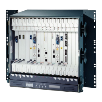
Page 52: Chapter 1 Shelf And Backplane Hardware
BNC/SMB connectors. You can mount the ONS 15454 in a 19- or 23-inch rack (482.6 or 584.2 mm). The shelf assembly weighs approximately 55 pounds (24.94 kg) with no cards installed. The shelf assembly includes a front door for added security, a fan tray module for cooling, and extensive cable-management space. -
Page 53: Rack Installation
Part 7 1.2 Rack Installation The ONS 15454 is mounted in a 19- or 23-in. (482.6- or 584.2-mm) equipment rack. The shelf assembly projects five inches (127 mm) from the front of the rack. It mounts in both Electronic Industries Alliance (EIA) standard and Telcordia-standard racks. -
Page 54: Reversible Mounting Bracket
Caution electromechanical corrosion of the hardware and joined material. When mounting the ONS 15454 in a frame with a nonconductive coating (such as paint, lacquer, or Caution enamel) either use the thread-forming screws provided with the ONS 15454 shipping kit, or remove the coating from the threads to ensure electrical continuity. -
Page 55: Mounting A Single Node
(2,133 mm) racks can hold four ONS 15454 shelves and a fuse and alarm panel. However, unequal flange racks are limited to three ONS 15454 shelves and a fuse and alarm panel or four ONS 15454 shelves and a fuse and alarm panel from an adjacent rack. -
Page 56: Front Door
ONS 15454. These LEDs must be visible so technicians can quickly determine if any alarms are present on the ONS 15454 shelf or the network. You can use the LCD to further isolate alarms. The front door... -
Page 57: Figure 1-4 Cisco Ons 15454 Deep Door
Cisco ONS 15454 Deep Door The ONS 15454 door locks with a pinned hex key that ships with the ONS 15454. A button on the right side of the shelf assembly releases the door. You can remove the front door of the ONS 15454 to provide unrestricted access to the front of the shelf assembly. -
Page 58: Figure 1-5 Ons 15454 Front Door Ground Strap
Chapter 1 Shelf and Backplane Hardware 1.3 1.3 Front Door Figure 1-5 ONS 15454 Front Door Ground Strap Figure 1-6 shows how to remove the front door. Cisco ONS 15454 Reference Manual, R7.0.1 OL-9217-01... - Page 59 An erasable label is pasted on the inside of the front door (Figure 1-7). You can use the label to record slot assignments, port assignments, card types, node ID, rack ID, and serial number for the ONS 15454. Cisco ONS 15454 Reference Manual, R7.0.1 OL-9217-01...
-
Page 60: Backplane Covers
Figure 1-9 on page 1-11. Each cover is held in place with nine 6-32 x 3/8 inch Phillips screws. See the “1.5 Electrical Interface Assemblies” section on page 1-14 for information on EIAs. Note Cisco ONS 15454 Reference Manual, R7.0.1 1-10 OL-9217-01... -
Page 61: Figure 1-9 Backplane Covers
Cover 1.4.1 Lower Backplane Cover The lower section of the ONS 15454 backplane is covered by either a clear plastic protector (15454-SA-ANSI) or a sheet metal cover (15454-SA-HD), which is held in place by five 6-32 x 1/2 inch screws. Remove the lower backplane cover to access the alarm interface panel (AIP), alarm pin fields,... -
Page 62: Figure 1-11 Backplane Attachment For Cover
Shelf and Backplane Hardware 1.4 1.4.2 Rear Cover 1.4.2 Rear Cover The ONS 15454 has an optional clear plastic rear cover. This clear plastic cover provides additional protection for the cables and connectors on the backplane. Figure 1-11 shows the rear cover screw locations. -
Page 63: Figure 1-12 Installing The Plastic Rear Cover With Spacers
The AIP is located above the alarm contacts on the lower section of the backplane. The AIP provides surge protection for the ONS 15454. It also provides an interface from the backplane to the fan-tray assembly and LCD. The AIP plugs into the backplane using a 96-pin DIN connector and is held in place with two retaining screws. -
Page 64: Electrical Interface Assemblies
AMP Champ on Side A and BNC on Side B or High-Density BNC on Side A and SMB on Side B, and so forth). As you face the rear of the ONS 15454 shelf assembly, the right side is the A side and the left side is the B side. -
Page 65: Table 1-1 Eia Types Compatible With The 15454-Sa-Ansi Only
Optional EIA backplane covers are typically preinstalled when ordered with the ONS 15454. A minimal amount of assembly might be required when EIAs are ordered separately from the ONS 15454. If you are installing EIAs after the shelf assembly is installed, plug the EIA into the backplane. The EIA has six electrical connectors that plug into six corresponding backplane connectors. -
Page 66: Table 1-2 Eia Configurations Compatible With The 15454-Sa-Ansi And The 15454-Sa-Hd
Slot 1 15454-EIA-BNC-A96= 96 pairs of Slot 12 15454-EIA-BNC-A96= MiniBNC MiniBNC DS-3/EC1-48 Slot 2 Slot 13 connectors connectors DS3XM-6 Slot 4 Slot 14 DS3XM-12 Slot 5 Slot 16 EC-1 Slot 6 Slot 17 Cisco ONS 15454 Reference Manual, R7.0.1 1-16 OL-9217-01... -
Page 67: Bnc Eia
1.5.3 BNC EIA The ONS 15454 BNC EIA supports 24 DS-3 circuits on each side of the ONS 15454 (24 transmit and 24 receive connectors). If you install BNC EIAs on both sides of the shelf assembly, the ONS 15454 hosts up to 48 circuits. -
Page 68: Figure 1-13 Bnc Backplane For Use In 1:1 Protection Schemes
1.5 1.5.3 BNC EIA type. Use RG-59/U cable to connect to the ONS 15454 BNC EIA. These cables are recommended to connect to a patch panel and are designed for long runs. You can use BNC EIAs for DS-3 (including the DS3XM-6 and DS3XM-12) or EC-1 cards. -
Page 69: Figure 1-14 Bnc Insertion And Removal Tool
Phone: 800 982-2629 Fax: 818 706-1040 1.5.4 High-Density BNC EIA The ONS 15454 high-density BNC EIA supports 48 DS-3 circuits on each side of the ONS 15454 (48 transmit and 48 receive connectors). If you install BNC EIAs on both sides of the unit, the ONS 15454 hosts up to 96 circuits. -
Page 70: Figure 1-15 High-Density Bnc Backplane For Use In 1:N Protection Schemes
(A and B) through 192 miniBNC connectors on each side. If you install BNC EIAs on both sides of the unit, the ONS 15454 hosts up to 192 circuits. The MiniBNC EIAs are designed to support DS-3 and EC-1 signals. -
Page 71: Table 1-3 Minibnc Protection Types And Slots
1.5.5.1 MiniBNC Connectors You can install MiniBNCs on one or both sides of the ONS 15454. As you face the rear of the ONS 15454 shelf assembly, the right side is the A side (15454-EIA-BNC-A96) and the left side is the B side (15454-EIA-BNC-A96). -
Page 72: Figure 1-16 Minibnc Backplane For Use In 1:N Protection Schemes
Chapter 1 Shelf and Backplane Hardware 1.5 1.5.5 MiniBNC EIA Figure 1-16 MiniBNC Backplane for Use in 1:N Protection Schemes Cisco ONS 15454 Reference Manual, R7.0.1 1-22 OL-9217-01... -
Page 73: Table 1-4 J-Labeling Port Assignments For A Shelf Assembly Configure With Low-Density Electrical Cards (A Side)
— 1–12 — LD DS-3 — — — — — 1–12 — — LD DS-3 — 1–12 — — — — — — LD DS-3 — — 1–12 — — — — Cisco ONS 15454 Reference Manual, R7.0.1 1-23 OL-9217-01... -
Page 74: Table 1-5 J-Labeling Port Assignments For A Shelf Assembly Configured With Low-Density Electrical Cards (B Side)
— — LD DS-3 — — 1–12 — — — — Table 1-6 Table 1-7 show the J-labeling and corresponding card ports for a shelf assembly configured with high-density 48-port DS-3/EC-1electrical cards. Cisco ONS 15454 Reference Manual, R7.0.1 1-24 OL-9217-01... -
Page 75: Table 1-6 J-Labeling Port Assignments For A Shelf Configured With High-Density Electrical Cards (A Side)
Cards (A Side) Slot Port Type Ports Ports Ports Ports Ports Ports Ports Ports HD DS-3 1–12 13–24 25–36 37–48 — — — — HD DS-3 — — — — 1–12 13–24 25–36 37–48 Cisco ONS 15454 Reference Manual, R7.0.1 1-25 OL-9217-01... -
Page 76: Minibnc Insertion And Removal Tool
Due to the large number of MiniBNC connectors on the MiniBNC EIA, you might require a special tool for inserting and removing MiniBNC EIAs (Figure 1-17). This tool also helps with ONS 15454 patch panel connections. Cisco ONS 15454 Reference Manual, R7.0.1... -
Page 77: Smb Eia
AMP 415484-2 (75-ohm) connectors. Use RG-179/U cable to connect to the ONS 15454 EIA. Cisco recommends these cables for connection to a patch panel; they are not designed for long runs. Range does not affect loopback testing. -
Page 78: Amp Champ Eia
RX TX for DS-1s The SMB EIA has 84 transmit and 84 receive connectors on each side of the ONS 15454 for a total of 168 SMB connectors (84 circuits). The EIA side marked “A” hosts 84 SMB connectors in six columns of 14 connectors. The “A” side columns are numbered 1 to 6 and correspond to Slots 1 to 6 on the shelf assembly. - Page 79 Table 1-8 shows the pin assignments for the AMP Champ connectors on the ONS 15454 AMP Champ EIA. The EIA side marked “A” hosts six AMP Champ connectors. The connectors are numbered 1 to 6 for the corresponding slots on the shelf assembly. Each AMP Champ connector on the backplane supports 14 DS-1 ports for a DS1-14 card, and each connector features 28 live pairs—one transmit pair...
-
Page 80: Table 1-8 Amp Champ Connector Pin Assignments
Tx Spare1– N/A Rx Spare1+ N/A Rx Spare1– N/A Table 1-9 shows the pin assignments for the AMP Champ connectors on the ONS 15454 AMP Champ EIA for a shielded DS-1 cable. Table 1-9 AMP Champ Connector Pin Assignments (Shielded DS-1 Cable) - Page 81 When the DS1N-14 card is installed in an ONS 15454 shelf that has an AMP Champ EIA, the cable that connects the AMP Champ connector with the traffic source must be connected to the ground on both the sides to meet the EMC standard.
-
Page 82: Ubic-V Eia
You can install UBIC-Vs on one or both sides of the ONS 15454. As you face the rear of the ONS 15454 shelf assembly, the right side is the A side (15454-EIA-UBICV-A) and the left side is the B side (15454-EIA-UBICV-B). -
Page 83: Ubic-H Eia
UBIC-V board. When installed with the standard door and cabling on the backplane, the ONS 15454 shelf measures approximately 15.7 inches (399 mm) deep when partially populated with backplane cables, 16.1 inches (409 mm) deep when fully populated, and 16.75 inches (425 mm) deep with the rear cover installed. - Page 84 1.5 1.5.9 UBIC-H EIA You can install UBIC-Hs on one or both sides of the ONS 15454. As you face the rear of the ONS 15454 shelf assembly, the right side is the A side (15454-EIA-UBICH-A) and the left side is the B side (15454-EIA-UBICH-B).
-
Page 85: Table 1-11 J-Labeling Port Assignments For A Shelf Assembly Configured With Low-Density Electrical Cards (A Side)
— — 1–12 — — — — — Tables 1-13 1-14 show the J-labeling and corresponding card ports for a shelf assembly configured with high-density 48-port DS-3/EC-1 or 56-port DS-1 electrical cards. Cisco ONS 15454 Reference Manual, R7.0.1 1-35 OL-9217-01... -
Page 86: Table 1-13 J-Labeling Port Assignments For A Shelf Configured With High-Density Electrical Cards (A Side)
14.5 inches deep when fully populated with backplane cables, and 15.0 inches deep with the rear cover installed. When installed with the deep door and cabling on the backplane, the ONS 15454 shelf measures approximately 16.5 inches deep when fully populated with backplane cables, and 17.0 inches deep with the rear cover installed. -
Page 87: Eia Replacement
1.5.10 EIA Replacement Before you attach a new EIA, you must remove the backplane cover or EIA already installed on the ONS 15454. Refer to the spare document(s) for the EIA type(s) you are removing and replacing for specific information. -
Page 88: Electrical Interface Adapters
ESD jack located on the lower-right outside edge of the shelf assembly. If you use DS-1 electrical twisted-pair cables, equip the ONS 15454 with an SMB EIA on each side of the backplane where DS-1 cables will terminate. You must install special DS-1 electrical interface adapters, commonly referred to as a balun, on every transmit and receive connector for each DS-1 termination. -
Page 89: Ubic-V Cables
#24 AWG twisted pairs on the far end and are color coded as identified in Table 1-17. The following DS-1 cables are no longer available from Cisco Systems for use with the UBIC-V EIA: DS-1 cable, 150 feet: 15454-CADS1-SD •... -
Page 90: Table 1-16 Ubic-V Ds-1 Scsi Connector Pin Out
FGnd FGnd FGnd FGnd FGnd FGnd FGnd FGnd FGnd FGnd FGnd FGnd FGnd FGnd FGnd FGnd FGnd FGnd FGnd FGnd FGnd FGnd FGnd FGnd FGnd FGnd FGnd FGnd FGnd FGnd FGnd FGnd Cisco ONS 15454 Reference Manual, R7.0.1 1-40 OL-9217-01... -
Page 91: Figure 1-24 Ubic-V Ds-1 Cable Schematic Diagram
1:1.15 DS1 75Ω Tip DS1 #14 Pin 50 100Ω Differential DS-1 Port #14 To/From DSx 75Ω Signal To/From UBIC-V Ring DS1 #14 FGND Table 1-17 shows the UBIC-V DS-1 Tip/Ring color coding. Cisco ONS 15454 Reference Manual, R7.0.1 1-41 OL-9217-01... -
Page 92: Table 1-17 Ubic-V Ds-1 Tip/Ring Color Coding
UBIC-V DS-3/EC-1 SCSI Connector Pin Out Port SCSI Pin SCSI Pin Port FGnd FGnd FGnd FGnd FGnd FGnd FGnd FGnd FGnd FGnd FGnd FGnd FGnd FGnd FGnd FGnd FGnd FGnd FGnd FGnd FGnd FGnd FGnd FGnd Cisco ONS 15454 Reference Manual, R7.0.1 1-42 OL-9217-01... - Page 93 UBIC-V DS-3/EC-1 SCSI Connector Pin Out (continued) Port SCSI Pin SCSI Pin Port FGnd FGnd FGnd FGnd FGnd FGnd FGnd FGnd FGnd FGnd FGnd FGnd Not connected Not connected Figure 1-25 shows the UBIC-V DS-3/EC-1 cable schematic diagram. Cisco ONS 15454 Reference Manual, R7.0.1 1-43 OL-9217-01...
-
Page 94: Ubic-H Cables
The UBIC-H EIA is designed to support DS-1, DS-3, or EC-1 signals. The type of signal supported is determined by the UBIC-H cable assembly that you order. To support DS-1 signals, select the DS-1 UBIC-H cable assembly (part number 15454-CADS1-H-<length>). Cisco ONS 15454 Reference Manual, R7.0.1 1-44 OL-9217-01... - Page 95 #24 AWG twisted pairs on the far end and are color coded as identified in Table 1-20. The following DS-1 cables are available from Cisco Systems for use with the UBIC-H EIA: 25 feet: 15454-CADS1-H-25 • 50 feet: 15454-CADS1-H-50 •...
-
Page 96: Figure 1-23 Cable Connector Pins
FGnd FGnd FGnd FGnd FGnd FGnd FGnd FGnd FGnd FGnd FGnd FGnd FGnd FGnd FGnd FGnd FGnd FGnd FGnd FGnd FGnd FGnd FGnd FGnd FGnd FGnd FGnd FGnd FGnd FGnd FGnd FGnd Cisco ONS 15454 Reference Manual, R7.0.1 1-46 OL-9217-01... -
Page 97: Figure 1-27 Ubic-H Ds-1 Cable Schematic Diagram
To/From UBIC-H Ring DS1 #13 FGND 1:1.15 DS1 75Ω Tip DS1 #14 Pin 50 Port #14 75Ω Signal To/From UBIC-H Ring DS1 #14 FGND Table 1-20 shows the UBIC-H DS-1 Tip/Ring color coding. Cisco ONS 15454 Reference Manual, R7.0.1 1-47 OL-9217-01... -
Page 98: Table 1-20 Ubic-H Ds-1 Tip/Ring Color Coding
UBIC-H DS-3/EC-1 SCSI Connector Pin Out Port SCSI Pin SCSI Pin Port FGnd FGnd FGnd FGnd FGnd FGnd FGnd FGnd FGnd FGnd FGnd FGnd FGnd FGnd FGnd FGnd FGnd FGnd FGnd FGnd FGnd FGnd FGnd FGnd Cisco ONS 15454 Reference Manual, R7.0.1 1-48 OL-9217-01... - Page 99 UBIC-H DS-3/EC-1 SCSI Connector Pin Out (continued) Port SCSI Pin SCSI Pin Port FGnd FGnd FGnd FGnd FGnd FGnd FGnd FGnd FGnd FGnd FGnd FGnd Not connected Not connected Figure 1-28 shows the UBIC-H DS-3/EC-1 cable schematic diagram Cisco ONS 15454 Reference Manual, R7.0.1 1-49 OL-9217-01...
-
Page 100: Ethernet Cables
Ethernet cables use RJ-45 connectors, and are straight-through or crossover, depending on what is connected to them. Table 1-22 shows 100Base-TX connector pin assignments, used with E100 Ethernet cards in the ONS 15454. Cisco ONS 15454 Reference Manual, R7.0.1 1-50 OL-9217-01... -
Page 101: Figure 1-29 100Baset Connector Pins
Ethernet cable schematic. Use a straight-through cable when connecting to a router or a PC. Figure 1-30 Straight-Through Cable Switch Router or PC 3 TD+ 3 RD+ 6 TD– 6 RD– 1 RD+ 1 TD+ 2 RD– 2 TD– Cisco ONS 15454 Reference Manual, R7.0.1 1-51 OL-9217-01... -
Page 102: Cable Routing And Management
1 RD+ 1 RD+ 2 RD– 2 RD– 1.11 Cable Routing and Management The ONS 15454 cable management facilities include the following: • A cable-routing channel (behind the fold-down door) that runs the width of the shelf assembly (Figure 1-32) Plastic horseshoe-shaped fiber guides at each side opening of the cable-routing channel that ensure •... -
Page 103: Fiber Management
Table 1-23 gives the maximum capacity of the fiber channel for each side of the shelf, for the different fiber sizes. Figure 1-33 Fiber Capacity Fiber guides Cisco ONS 15454 Reference Manual, R7.0.1 1-53 OL-9217-01... -
Page 104: Fiber Management Using The Tie-Down Bar
Figure 1-34 shows the tie-down bar, the ONS 15454, and the rack. Figure 1-34 Tie-Down Bar Tie-down bar Cisco ONS 15454 Reference Manual, R7.0.1... -
Page 105: Coaxial Cable Management
EIAs have cable management eyelets to tiewrap or lace cables to the cover panel. Tie wrap or lace the AMP Champ cables according to local site practice and route the cables. If you configure the ONS 15454 for a 23-inch (584.2 mm) rack, two additional inches (50.8 mm) of cable management area is available on each side of the shelf assembly. -
Page 106: Wire-Wrap And Pin Connections
60 VDC, anda maximum current of 100 mA. See the “2.7.2 External Alarms and Controls” section on page 2-29 for further information. 1.12.1 Wire-Wrap and Pin Connections Figure 1-37 shows the wire-wrapping connections on the backplane. Cisco ONS 15454 Reference Manual, R7.0.1 1-56 OL-9217-01... - Page 107 AE_CLK_N AE_CLK_N Yellow AE_DIN_P AE_DOUT_P Orange AE_DIN_N AE_DOUT_N AE_DOUT_P AE_DIN_P Brown AE_DOUT_N AE_DIN_N Figure 1-38 is a circuit diagram of the alarm inputs (Inputs 1 and 32 are shown in the example). Cisco ONS 15454 Reference Manual, R7.0.1 1-57 OL-9217-01...
-
Page 108: Figure 1-38 Alarm Input Circuit Diagram
Pin Number Signal Name Pin Number Signal Name ALARM_IN_1– ALARM_IN_2– ALARM_IN_3– ALARM_IN_4– ALARM_IN_5– ALARM_IN_6– ALARM_IN_7– ALARM_IN_8– ALARM_IN_9– ALARM_IN_10– ALARM_IN_11– ALARM_IN_12– ALARM_IN_13– ALARM_IN_14– ALARM_IN_15– ALARM_IN_16– ALARM_IN_17– ALARM_IN_18– ALARM_IN_19– ALARM_IN_20– ALARM_IN_21– ALARM_IN_22– ALARM_IN_23– ALARM_IN_24– ALARM_IN_25– Cisco ONS 15454 Reference Manual, R7.0.1 1-58 OL-9217-01... -
Page 109: Figure 1-39 Alarm Output Circuit Diagram
Table 1-26 Pin Association for Alarm Output Pins AMP Champ AMP Champ Pin Number Signal Name Pin Number Signal Name N.C. COM_0 COM_1 N.C. NO_1 NO_2 N.C. COM_2 COM_3 N.C. NO_3 NO_4 Cisco ONS 15454 Reference Manual, R7.0.1 1-59 OL-9217-01... -
Page 110: Filler Card
1.13 Filler Card Filler cards are designed to occupy empty multiservice and AIC-I slots in the Cisco ONS 15454 (Slots 1–6, 9, and 12 – 17). The filler card cannot operate in the XC slots (Slots 8 and 10) or TCC slots (7 and 11). -
Page 111: Fan-Tray Assembly
1.14 Fan-Tray Assembly The fan-tray assembly is located at the bottom of the ONS 15454 bay assembly. The fan tray is a removable drawer that holds fans and fan-control circuitry for the ONS 15454. The front door can be left in place or removed before installing the fan-tray assembly. -
Page 112: Fan Speed And Power Requirements
Caution assemblies (15454-SA-ANSI, P/N: 800-19857; 15454-SA-HD, P/N: 800-24848). The fan-tray assembly has a pin that prevents it from being installed in ONS 15454 shelf assemblies released before ONS 15454 Release 3.1 (15454-SA-NEBS3E, 15454-SA-NEBS3, and 15454-SA-R1, P/N: 800-07149). Equipment damage can result from attempting to install the 15454-FTA3 in a noncompatible shelf assembly. -
Page 113: Air Filter
(2.588 mm² [0.1018 inch]), with an integral lock washer. The lug must be a dual-hole type and rated to accept the #6 AWG (4.115 mm² [0.162 inch]) cable. Two posts are provided on the Cisco ONS 15454 to accommodate the dual-hole lug. -
Page 114: Alarm, Timing, Lan, And Craft Pin Connections
ESD jack located on the lower-right outside edge of the shelf assembly. The ONS 15454 has a backplane pin field located at the bottom of the backplane. The backplane pin field provides 0.045 square inch (29 mm ) wire-wrap pins for enabling external alarms, timing input and output, and craft interface terminals. -
Page 115: Figure 1-42 Ons 15454 Backplane Pinouts (Release 3.4 Or Later)
Chapter 1 Shelf and Backplane Hardware 1.16 1.16 Alarm, Timing, LAN, and Craft Pin Connections Figure 1-42 ONS 15454 Backplane Pinouts (Release 3.4 or Later) BITS ENVIRONMENTAL ALARMS MODEM CRAFT LOCAL ALARMS IN/OUT FG10 FG11 FG12 Field Function Field Function BITS BITS Output 2 negative (–) -
Page 116: Alarm Contact Connections
Each alarm contact consists of two wire-wrap pins on the shelf assembly backplane. Visual and audible alarm contacts are classified as critical, major, minor, and remote. Figure 1-43 shows alarm pin assignments. Cisco ONS 15454 Reference Manual, R7.0.1 1-66 OL-9217-01... -
Page 117: Timing Connections
Table 1-29 shows the LAN pin assignments. Before you can connect an ONS 15454 to other ONS 15454s or to a LAN, you must change the default IP address that is shipped with each ONS 15454 (192.1.0.2). Cisco ONS 15454 Reference Manual, R7.0.1... -
Page 118: Tl1 Craft Interface Installation
You can use the craft pins on the ONS 15454 backplane or the EIA/TIA-232 port on the TCC2/TCC2P card faceplate to create a VT100 emulation window to serve as a TL1 craft interface to the ONS 15454. Use a straight-through cable to connect to the EIA/TIA-232 port. -
Page 119: Card Slot Requirements
1.17.1 Card Slot Requirements The ONS 15454 shelf assembly has 17 card slots numbered sequentially from left to right. Slots 1 to 6 and 12 to 17 are multiservice slots that are used for electrical, optical, and Ethernet cards (traffic cards). -
Page 120: Table 1-31 Slot And Card Symbols
Color/Shape Definition Orange/Circle Slots 1 to 6 and 12 to 17. Only install ONS 15454 cards with a circle symbol on the faceplate. Blue/Triangle Slots 5, 6, 12, and 13. Only install ONS 15454 cards with circle or a triangle symbol on the faceplate. - Page 121 9.95 Gbps (STS-192) Faceplate SH 1550 OC192 LR/STM64 9.95 Gbps (STS-192) Faceplate LH 1550 OC192 LR/STM64 9.95 Gbps (STS-192) Faceplate LH ITU 15xx.xx FC_MR-4 4 (only 2 1.0625 Gbps Faceplate available in R4.6) Cisco ONS 15454 Reference Manual, R7.0.1 1-71 OL-9217-01...
-
Page 122: Card Replacement
1.17.2 Card Replacement To replace an ONS 15454 card with another card of the same type, you do not need to make any changes to the database; remove the old card and replace it with a new card. To replace a card with a card of a different type, physically remove the card and replace it with the new card, then delete the original card from CTC. -
Page 123: Software And Hardware Compatibility
1.18 Software and Hardware Compatibility Table 1-33 shows ONS 15454 software and hardware compatibility for nodes configured with XC or XCVT cards for Releases 4.6, 4.7, 5.0, 6.0, and 7.0. For software compatibility for a specific card, refer to the following URL: http://cisco.com/en/US/products/hw/optical/ps2006/prod_eol_notices_list.html... - Page 124 Chapter 1 Shelf and Backplane Hardware 1.18 1.18 Software and Hardware Compatibility Table 1-33 ONS 15454 Software and Hardware Compatibility—XC and XCVT Configurations (continued) Shelf 4.6.0x 5.0.0x 6.0.0x 7.0.0x Hardware Assembly (4.6) (5.0) (6.0) (7.0) ML1000-2 Fully compatible Fully compatible...
-
Page 125: Table 1-34 Ons 15454 Software And Hardware Compatibility-Xc10G And Xc-Vxc-10G Configurations
1. The XC card does not support features new to Release 5.0 and greater. 2. The shelf assemblies supported are 15454-SA-HD, 15454-SA-ANSI, and 15454-NEBS3E. 3. DS3 card having the part number 87-31-0001 does not work in Cisco ONS 15454 R8.0 and later. 4. ML-MR-10 and CE-MR-10 cards are not supported on XCVT. - Page 126 Chapter 1 Shelf and Backplane Hardware 1.18 1.18 Software and Hardware Compatibility Table 1-34 ONS 15454 Software and Hardware Compatibility—XC10G and XC-VXC-10G Configurations (continued) Shelf Hardware Assembly 4.6.0x (4.6) 5.0.0x (5.0) 6.0.0x (6.0) 7.0.0x (7.0) DS3-12 Fully compatible Fully compatible...
- Page 127 1. The shelf assemblies supported are 15454-SA-HD and 15454-SA-ANSI. 2. DS3 card having the part number 87-31-0001 does not work in Cisco ONS 15454 R8.0 and later. 3. Slots 1 to 4 and 14 to 17 give a total bandwidth of up to 2.5 Gb/s. Slots 5, 6, 12 , and 13 give a total bandwidth of up to 10 Gb/s 4.
- Page 128 Chapter 1 Shelf and Backplane Hardware 1.18 1.18 Software and Hardware Compatibility Cisco ONS 15454 Reference Manual, R7.0.1 1-78 OL-9217-01...
-
Page 129: Chapter 2 Common Control Cards
The card overview section summarizes card functions and compatibility. Each card is marked with a symbol that corresponds to a slot (or slots) on the ONS 15454 shelf assembly. The cards are then installed into slots displaying the same symbols. See the “1.17.1 Card Slot... -
Page 130: Table 2-1 Common Control Card Functions
“2.6 XC-VXC-10G Card” section on Tributary/Virtual Container (XC-VXC-10G) card page 2-22. serves as the switching matrix for the Cisco 15454 ANSI multiservice platform. The module operates as a superset of the XCVT or XC10G cross-connect module. The XC-VXC-10G card provides a... -
Page 131: Card Compatibility
1. The XC card does not support features new to Release 5.0 and greater. 2.1.3 Cross-Connect Card Compatibility The following tables list the compatible cross-connect cards for each Cisco ONS 15454 common-control card. The tables are organized according to type of common-control card. In the tables below, “Yes”... -
Page 132: Table 2-4 Electrical Card Cross-Connect Compatibility
Table 2-5 Optical Card Cross-Connect Compatibility Optical Card XCVT Card XC10G Card XC-VXC-10GCard OC3 IR 4 1310 OC3 IR 4/STM1 SH 1310 OC3 IR /STM1SH 1310-8 — OC12 IR 1310 OC12 LR 1310 Cisco ONS 15454 Reference Manual, R7.0.1 OL-9217-01... - Page 133 XC-VXC-10G Card E100T-12 — — E1000-2 — — E100T-G E1000-2-G G1K-4 Yes, in Slots 5, 6, 12, 13 ML100T-12 Yes, in Slots 5, 6, 12, 13 ML1000-2 Yes, in Slots 5, 6, 12, 13 Cisco ONS 15454 Reference Manual, R7.0.1 OL-9217-01...
-
Page 134: Tcc2 Card
The TCC2 card performs system initialization, provisioning, alarm reporting, maintenance, diagnostics, IP address detection/resolution, SONET section overhead (SOH) DCC/GCC termination, and system fault detection for the ONS 15454. The TCC2 also ensures that the system maintains Stratum 3 (Telcordia GR-253-CORE) timing requirements. It monitors the supply voltage of the system. -
Page 135: Tcc2 Card Functionality
84 DCCs can be routed over the TCC2 card and up to 84 section DCCs can be terminated at the TCC2 card (subject to the available optical digital communication channels). The TCC2 card selects and processes 84 DCCs to facilitate remote system management interfaces. Cisco ONS 15454 Reference Manual, R7.0.1 OL-9217-01... -
Page 136: Tcc2 Card-Level Indicators
10BASE T, half duplex. Full duplex and autonegotiate settings should not be used because they might result in a loss of visibility to the node. Note Cisco does not support operation of the ONS 15454 with only one TCC2 card. For full functionality and to safeguard your system, always operate with two TCC2 cards. Note When a second TCC2 card is inserted into a node, it synchronizes its software, its backup software, and its database with the active TCC2. -
Page 137: Network-Level Indicators
The ACO button opens the audible alarm closure on the backplane. ACO is stopped if a new alarm occurs. After the originating alarm is cleared, the ACO LED and audible alarm control are reset. Cisco ONS 15454 Reference Manual, R7.0.1 OL-9217-01... -
Page 138: Power-Level Indicators
The TCC2P card performs system initialization, provisioning, alarm reporting, maintenance, diagnostics, IP address detection/resolution, SONET SOH DCC/GCC termination, and system fault detection for the ONS 15454. The TCC2P card also ensures that the system maintains Stratum 3 (Telcordia GR-253-CORE) timing requirements. It monitors the supply voltage of the system. -
Page 139: Tcc2P Functionality
Up to 84 DCCs can be routed over the TCC2P card and up to 84 section DCCs can be terminated at the TCC2P card (subject to the available optical digital communication channels). The TCC2P selects and processes 84 DCCs to facilitate remote system management interfaces. Cisco ONS 15454 Reference Manual, R7.0.1 2-11 OL-9217-01... - Page 140 10BASE T, half duplex. Full duplex and autonegotiate settings should not be used because they might result in a loss of visibility to the node. Note Cisco does not support operation of the ONS 15454 with only one TCC2P card. For full functionality and to safeguard your system, always operate with two TCC2P cards. Note When a second TCC2P card is inserted into a node, it synchronizes its software, its backup software, and its database with the active TCC2P card.
-
Page 141: Tcc2P Card-Level Indicators
After pressing the ACO button, the ACO LED turns green. The ACO button opens the audible alarm closure on the backplane. ACO is stopped if a new alarm occurs. After the originating alarm is cleared, the ACO LED and audible alarm control are reset. Cisco ONS 15454 Reference Manual, R7.0.1 2-13 OL-9217-01... -
Page 142: Power-Level Indicators
The XCVT provides STS-48 capacity to Slots 5, 6, 12, and 13, and STS-12 capacity to Slots 1 to 4 and 14 to 17. Any STS-1 on any port can be connected to any other port, meaning that the STS cross-connections are nonblocking. Figure 2-3 shows the XCVT faceplate and block diagram. Cisco ONS 15454 Reference Manual, R7.0.1 2-14 OL-9217-01... -
Page 143: Xcvt Functionality
288 STS bidirectional ports • 144 STS bidirectional cross-connects 672 VT1.5 ports via 24 logical STS ports • 336 VT1.5 bidirectional cross-connects • Nonblocking at the STS level • STS-1/3c/6c/12c/48c cross-connects • Cisco ONS 15454 Reference Manual, R7.0.1 2-15 OL-9217-01... -
Page 144: Vt Mapping
CTC. The TCC2/TCC2P cards establish the proper internal cross-connect information and relay the setup information to the XCVT card. Do not operate the ONS 15454 with only one cross-connect card. Two cross-connect cards of the same Caution type (two XCVT or two XC10G cards) must always be installed. -
Page 145: Xcvt Hosting Ds3Xm-6 Or Ds3Xm-12
VT1.5 payloads. The VT1.5s can then be cross-connected by the XCVT card. The XCVT card can host a maximum of 336 bidirectional VT1.5s. 2.4.4 XCVT Card-Level Indicators Table 2-15 shows the two card-level LEDs on the XCVT card faceplate. Cisco ONS 15454 Reference Manual, R7.0.1 2-17 OL-9217-01... -
Page 146: Xc10G Card
576 STS-1 cross-connections through 1152 STS-1 ports. Any STS-1 on any port can be connected to any other port, meaning that the STS cross-connections are nonblocking. Figure 2-5 shows the XC10G faceplate and block diagram. Cisco ONS 15454 Reference Manual, R7.0.1 2-18 OL-9217-01... -
Page 147: Xc10G Functionality
TCC2/TCC2P cards assign bandwidth to each slot on a per STS-1 or per VT1.5 basis. Two cross-connect cards, installed in Slots 8 and 10, are required to operate the ONS 15454. You can establish cross-connect (circuit) information through the CTC. The cross-connect card establishes the proper internal cross-connect information and sends the setup information to the cross-connect card. -
Page 148: Vt Mapping
Chapter 2 Common Control Cards 2.5 2.5.2 VT Mapping Do not operate the ONS 15454 with only one XCVT or XC10G card. Two cross-connect cards of the Caution same type (either two XCVT or two XC10G cards) must always be installed. -
Page 149: Xc10G Hosting Ds3Xm-6 Or Ds3Xm-12
The FAIL LED flashes during the boot process. Replace the card if the red FAIL LED persists. ACT/STBY LED Indicates whether the XC10G is active and carrying traffic (green), or in standby mode to the active XC10G card (amber). Green (Active) Amber (Standby) Cisco ONS 15454 Reference Manual, R7.0.1 2-21 OL-9217-01... -
Page 150: Xcvt/Xc10G/Xc-Vxc-10G Compatibility
XC-VXC-10G cross-connect card is in use. Do not pair an XCVT card with an XC10G or XC-VXC-10G card. When upgrading from an XCVT to the XC10G or XC-VXC-10G card, refer to the “Upgrade Cards and Spans” chapter in the Cisco ONS 15454 Procedure Guide for more information. 2.6 XC-VXC-10G Card... -
Page 151: Xc-Vxc-10G Functionality
1344 bidirectional VT1.5 ports and 1008 bidirectional VT2 ports (mixed grooming) The TCC2/TCC2P card assigns bandwidth to each slot on a per STS-1, per VT1.5, or per VT2 basis. The switch matrices are fully crosspoint and broadcast supporting. Cisco ONS 15454 Reference Manual, R7.0.1 2-23 OL-9217-01... - Page 152 The XC-VXC-10G can be used with either the standard ANSI shelf assembly (15454-SA- ANSI) or high-density shelf assembly (15454-SA-HD). Do not operate the ONS 15454 with only one XC-VXC-10G cross-connect card. Two cross-connect Caution cards must always be installed.
-
Page 153: Vt Mapping
1008 bidirectional VT 2 cross-connects, or Mixed grooming (50% VT1.5 and 50% VT2) 2.6.2 VT Mapping The VT structure is designed to transport and switch payloads below the DS-3 rate. The ONS 15454 performs VT mapping according to Telcordia GR-253-CORE standards. Table 2-16 shows the VT numbering scheme for the ONS 15454 as it relates to the Telcordia standard. -
Page 154: Xc-Vxc-10G Hosting Ds3Xm-6 Or Ds3Xm-12
The FAIL LED flashes during the boot process. Replace the card if the red FAIL LED persists. ACT/STBY LED Indicates whether the XC10G is active and carrying traffic (green), or in standby mode to the active XC10G card (amber). Green (Active) Amber (Standby) Cisco ONS 15454 Reference Manual, R7.0.1 2-26 OL-9217-01... -
Page 155: Xc-Vxc-10G Compatibility
If you are using Ethernet cards, the E1000-2-G or the E100T-G must be used when the XC-VXC-10G cross-connect card is in use. When upgrading from an XC10G card to an XC-VXC-10G card, refer to the “Upgrade Cards and Spans” chapter in the Cisco ONS 15454 Procedure Guide for more information. Also refer to the “2.1.2 Card Compatibility”... -
Page 156: Aic-I Card-Level Indicators
Indicates that the cards processor is not ready. The FAIL LED is on during Reset and flashes during the boot process. Replace the card if the red FAIL LED persists. Green ACT LED Indicates the AIC-I card is provisioned for operation. Cisco ONS 15454 Reference Manual, R7.0.1 2-28 OL-9217-01... -
Page 157: External Alarms And Controls
You cannot assign the fan-tray abbreviation for the alarm; the abbreviation reflects the generic name of the input contacts. The alarm condition remains raised until the external input stops driving the contact or you provision the alarm input. Cisco ONS 15454 Reference Manual, R7.0.1 2-29 OL-9217-01... -
Page 158: Orderwire
Both express and local orderwire can be configured as on or off on a particular SONET facility. The ONS 15454 supports up to four orderwire channel terminations per shelf. This allows linear, single ring, dual ring, and small hub-and-spoke configurations. -
Page 159: Power Monitoring
The AIC-I supports selective dual tone multifrequency (DTMF) dialing for telephony connectivity, which causes one AIC-I card or all ONS 15454 AIC-I cards on the orderwire subnetwork to “ring.” The ringer/buzzer resides on the AIC-I. There is also a “ring” LED that mimics the AIC-I ringer. It flashes when a call is received on the orderwire subnetwork. -
Page 160: Table 2-22 Udc Pin Assignments
The DCC features a dedicated data channel of 576 kbps (D4 to D12 bytes) between two nodes in an ONS 15454 network. Each AIC-I card provides two DCCs, DCC-A and DCC-B, through separate RJ-45 connectors on the front of the AIC-I card. Use a shielded RJ-45 cable. Each DCC can be routed to an individual optical interface in the ONS 15454. -
Page 161: Electrical Card Overview
3.10 DS3XM-12 Card, page 3-26 3.1 Electrical Card Overview Each card is marked with a symbol that corresponds to a slot (or slots) on the ONS 15454 shelf assembly. The cards are then installed into slots displaying the same symbols. See the “1.17 Cards and Slots”... -
Page 162: Table 3-1 Cisco Ons 15454 Electrical Cards
The DS3XM-12 card provides 12 Telcordia- See the “3.10 DS3XM-12 Card” (Transmux) compliant GR-499-CORE M13 multiplexing section on page 3-26. functions. The DS3XM-12 converts twelve framed DS-3 network connections to 28x12 or 168 VT1.5s. Cisco ONS 15454 Reference Manual, R7.0.1 OL-9217-01... -
Page 163: Table 3-2 Electrical Card Software Release Compatibility
An EC1-12 card can be 1:1 protected with another EC1-12 card but cannot protect more than one EC1-12 card. You must install the EC1-12 in an even-numbered slot to serve as a working card and in an odd-numbered slot to serve as a protect card. Cisco ONS 15454 Reference Manual, R7.0.1 OL-9217-01... -
Page 164: Figure 3-1 Ec1-12 Faceplate And Block Diagram
3.2.1 EC1-12 Slots and Connectors You can install the EC1-12 card in Slots 1 to 6 or 12 to 17 on the ONS 15454. Each EC1-12 interface features DSX-level (digital signal cross-connect frame) outputs supporting distances up to 450 feet (137 meters) depending on facility conditions. -
Page 165: Ec1-12 Hosted By Xcvt, Xc10G, Or Xc-Vxc-10G
3.2.5 EC1-12 Port-Level Indicators You can obtain the status of the EC1-12 card ports by using the LCD screen on the ONS 15454 fan tray. Use the LCD to view the status of any port or card slot; the screen displays the number and severity of alarms for a given port or slot. -
Page 166: Ds1N-14 Features And Functions
If you use the DS1N-14 as a standard DS-1 card in a 1:1 protection group, you can install the DS1N-14 card in Slots 1 to 6 or 12 to 17 on the ONS 15454. If you use the card’s 1:N functionality, you must install a DS1N-14 card in Slots 3 and 15. - Page 167 STS-1 / STS-12 STS1 to Cross Relay Interface 14 DS1 Mux/Demux Connect ASIC Units Matrix Mapper Matrix ASIC DRAM FLASH Figure 3-3 shows the DS1N-14 faceplate and a block diagram of the card. Cisco ONS 15454 Reference Manual, R7.0.1 OL-9217-01...
-
Page 168: Ds1-14 And Ds1N-14 Hosted By Xcvt, Xc10G, Or Xc-Vxc-10G
The XC10G and XCVT cards manage up to 336 bidirectional VT1.5 ports. The XC-VXC-10G card can manage up to 2688 bidirectional VT1.5 ports 3.3.5 DS1-14 and DS1N-14 Card-Level Indicators Table 3-4 describes the three card-level LEDs on the DS1-14 and DS1N-14 card faceplates. Cisco ONS 15454 Reference Manual, R7.0.1 OL-9217-01... -
Page 169: Ds1-14 And Ds1N-14 Port-Level Indicators
You can obtain the status of the DS1-14 and DS1N-14 card ports by using the LCD screen on the ONS 15454 fan-tray assembly. Use the LCD to view the status of any port or card slot; the screen displays the number and severity of alarms for a given port or slot. -
Page 170: Ds1/E1-56 Faceplate And Block Diagram
XC-VXC-10G and TCC2/TCC2P cards. You can install the DS1/E1-56 card in Slots 1 to 3 or 15 to 17 on the ONS 15454, but installing this card in certain slots will block the use of other slots. -
Page 171: Figure 3-4 Ds1/E1-56 Faceplate And Block Diagram
3 thru 6 not shown LINK to Analog Digital DS1/E1 x8 ports x8 ports Octal AD BUS PROC 3.4.3 DS1/E1-56 Card-Level Indicators The DS1/E1-56 card has three card-level LED indicators (Table 3-6). Cisco ONS 15454 Reference Manual, R7.0.1 3-11 OL-9217-01... -
Page 172: Ds1/E1-56 Port-Level Indicators
3.4.4 DS1/E1-56 Port-Level Indicators You can obtain the status of the DS1/E1-56 card ports by using the LCD screen on the ONS 15454 fan-tray assembly. Use the LCD to view the status of any port or card slot; the screen displays the number and severity of alarms for a given port or slot. -
Page 173: Ds3-12 And Ds3N-12 Slots And Connectors
3.5.1 DS3-12 and DS3N-12 Slots and Connectors You can install the DS3-12 or DS3N-12 card in Slots 1 to 6 or 12 to 17 on the ONS 15454. Each DS3-12 or DS3N-12 card port features DSX-level outputs supporting distances up to 137 meters (450 feet) depending on facility conditions. -
Page 174: Figure 3-6 Ds3N-12 Faceplate And Block Diagram
When the ACT/STBY LED is amber, the card is operational and Green (Active) in standby (protect) mode. Amber (Standby) Amber SF LED The amber SF LED indicates a signal failure or condition such as port LOS. Cisco ONS 15454 Reference Manual, R7.0.1 3-14 OL-9217-01... -
Page 175: Ds3-12 And Ds3N-12 Port-Level Indicators
XC-VXC-10G and TCC2/TCC2P cards. You can install the DS3/EC1-48 card in Slots 1 to 3 or 15 to 17 on the ONS 15454, but installing this card in certain slots will block the use of other slots. -
Page 176: Ds3/Ec1-48 Faceplate And Block Diagram
“7.2 Electrical Card Protection and the Backplane” section on page 7-5 for more information about electrical card slot protection and restrictions. 3.6.2 DS3/EC1-48 Faceplate and Block Diagram Figure 3-7 shows the DS3/EC1-48 faceplate and a block diagram of the card. Cisco ONS 15454 Reference Manual, R7.0.1 3-16 OL-9217-01... -
Page 177: Figure 3-7 Ds3/Ec1-48 Faceplate And Block Diagram
DS3/EC1 Mapper Ports & Protection Framer/ FPGA Mux/Relays Mapper/ (UBIC-V, UBIC-H, or PROTECT HD MiniBNC) IBPIA ASIC Processor 3.6.3 DS3/EC1-48 Card-Level Indicators The DS3/EC1-48 card has three card-level LED indicators (Table 3-9). Cisco ONS 15454 Reference Manual, R7.0.1 3-17 OL-9217-01... -
Page 178: Ds3/Ec1-48 Port-Level Indicators
3.6.4 DS3/EC1-48 Port-Level Indicators You can obtain the status of the DS3/EC1-48 card ports by using the LCD screen on the ONS 15454 fan-tray assembly. Use the LCD to view the status of any port or card slot; the screen displays the number and severity of alarms for a given port or slot. -
Page 179: Figure 3-8 Ds3I-N-12 Faceplate And Block Diagram
M-bit monitoring • F-bit monitoring • Far-end block error (FEBE) monitoring • Far-end alarm and control (FEAC) status and loop code detection • • Path trace byte support with TIM-P alarm generation Cisco ONS 15454 Reference Manual, R7.0.1 3-19 OL-9217-01... -
Page 180: Ds3I-N-12 Card-Level Indicators
3.7.3 DS3i-N-12 Port-Level Indicators You can find the status of the DS3i-N-12 card ports by using the LCD screen on the ONS 15454 fan-tray assembly. Use the LCD to view the status of any port or card slot; the screen displays the number and severity of alarms for a given port or slot. -
Page 181: Ds3-12E And Ds3N-12E Slots And Connectors
3.8.1 DS3-12E and DS3N-12E Slots and Connectors You can install the DS3-12E and DS3N-12E cards in Slots 1 to 6 or 12 to 17 on the ONS 15454. Each DS3-12E and DS3N-12E port features DSX-level outputs supporting distances up to 137 meters (450 feet). -
Page 182: Figure 3-9 Ds3-12E Faceplate And Block Diagram
Unit #1 BERT ASIC FPGA ASIC main DS3-m12 protect DS3-p12 Line Interface Unit #1 FPGA uP bus Processor SDRAM Flash Figure 3-10 shows the DS3N-12E faceplate and a block diagram of the card. Cisco ONS 15454 Reference Manual, R7.0.1 3-22 OL-9217-01... -
Page 183: Figure 3-10 Ds3N-12E Faceplate And Block Diagram
When the ACT/STBY LED is amber, the card is operational and Green (Active) in standby (protect) mode. Amber (Standby) Amber SF LED The amber SF LED indicates a signal failure or condition such as port LOS or AIS. Cisco ONS 15454 Reference Manual, R7.0.1 3-23 OL-9217-01... -
Page 184: Ds3-12E And Ds3N-12E Port-Level Indicators
You can find the status of the DS3-12E and DS3N-12E card ports by using the LCD screen on the ONS 15454 fan-tray assembly. Use the LCD to quickly view the status of any port or card slot; the screen displays the number and severity of alarms for a given port or slot. -
Page 185: Figure 3-11 Ds3Xm-6 Faceplate And Block Diagram
336 bidirectional VT1.5s on two DS3XM-6 cards. In most network configurations, two DS3XM-6 cards are paired together as working and protect cards. 3.9.4 DS3XM-6 Card-Level Indicators Table 3-12 describes the three card-level LEDs on the DS3XM-6 card faceplate. Cisco ONS 15454 Reference Manual, R7.0.1 3-25 OL-9217-01... -
Page 186: Ds3Xm-6 Port-Level Indicators
3.9.5 DS3XM-6 Port-Level Indicators You can find the status of the six DS3XM-6 card ports by using the LCD screen on the ONS 15454 fan-tray assembly. Use the LCD to quickly view the status of any port or card slot; the screen displays the number and severity of alarms for a given port or slot. -
Page 187: Ported Mode
XC10G/XC-VXC-10G Shelf Port Maximums (XCVT Card) XC-VXC-10G Cards) (any multiservice slot) Portless Ports Ported Ports Do not install low-density DS-1 cards in the same side of the shelf as DS3XM-12 cards. Caution Cisco ONS 15454 Reference Manual, R7.0.1 3-27 OL-9217-01... -
Page 188: Protection Modes
A combination of ported and portless connections is used but all the ported cards being protected are on the same side of the chassis as the protecting card. These protection groups can be implemented in the ONS 15454 SONET platform for both the A and B sides and do not require a special protect card. -
Page 189: Ds3Xm-12 Slots And Connectors
The card can be installed in Slots 1 to 6 or 12 to 17. Each DS3XM-12 port features DSX-level outputs supporting distances up to 137 meters (450 feet) depending on facility conditions. 3.10.8 DS3XM-12 Faceplate and Block Diagram Figure 3-12 shows the DS3XM-12 faceplate and a block diagram of the card. Cisco ONS 15454 Reference Manual, R7.0.1 3-29 OL-9217-01... -
Page 190: Ds3Xm-12 Card-Level Indicators
& Protection Framer/ FPGA DS3 LIU Mux/Relays Mapper PROTECT IBPIA ASIC DS3 Mapped STS’1s (Portless Mode) Processor 3.10.9 DS3XM-12 Card-Level Indicators Table 3-15 describes the three card-level LEDs on the DS3XM-12 card faceplate. Cisco ONS 15454 Reference Manual, R7.0.1 3-30 OL-9217-01... -
Page 191: Ds3Xm-12 Port-Level Indicators
3.10.10 DS3XM-12 Port-Level Indicators You can find the status of the twelve DS3XM-12 card ports by using the LCD screen on the ONS 15454 fan-tray assembly. Use the LCD to quickly view the status of any port or card slot; the screen displays the number and severity of alarms for a given port or slot. - Page 192 Chapter 3 Electrical Cards 3.10 3.10.10 DS3XM-12 Port-Level Indicators Cisco ONS 15454 Reference Manual, R7.0.1 3-32 OL-9217-01...
- Page 193 The terms "Unidirectional Path Switched Ring" and "UPSR" may appear in Cisco literature. These terms Note do not refer to using Cisco ONS 15xxx products in a unidirectional path switched ring configuration. Rather, these terms, as well as "Path Protected Mesh Network" and "PPMN," refer generally to Cisco's path protection feature, which may be used in any topological network configuration.
-
Page 194: Table 4-1 Optical Cards For The Ons 15454
• 4.1 Optical Card Overview Each card is marked with a symbol that corresponds to a slot (or slots) on the ONS 15454 shelf assembly. The cards are then installed into slots displaying the same symbols. See the “1.17 Cards and Slots”... -
Page 195: Card Summary
Chapter 4 Optical Cards 4.1 4.1.1 Card Summary Table 4-1 Optical Cards for the ONS 15454 (continued) Card Port Description For Additional Information... OC12 LR/STM4 The OC12 LR/STM4 LH 1550 card provides one See the “4.6 OC12 LH 1550 long-range OC-12 port and operates at 1550 nm. -
Page 196: Table 4-2 Optical Card Software Release Compatibility
1. In the Cisco Transport Controller (CTC) GUI, these cards are known as OC192-XFP. The Cisco OC3 IR/STM1 SH, OC12 IR/STM4 SH, and OC48 IR/STM16 SH interface optics, all Note working at 1310 nm, are optimized for the most widely used SMF-28 fiber, available from many suppliers. -
Page 197: Card Compatibility
4.2 OC3 IR 4/STM1 SH 1310 Card For hardware specifications, see the “A.6.1 OC3 IR 4/STM1 SH 1310 Card Specifications” section on Note page A-26. See Table 4-2 on page 4-4 for optical card compatibility. Cisco ONS 15454 Reference Manual, R7.0.1 OL-9217-01... -
Page 198: Oc3 Ir 4/Stm1 Sh 1310 Card
1310-nm laser and contains a transmit and receive connector (labeled) on the card faceplate. The card uses SC connectors. The OC3 IR 4/STM1 SH 1310 card supports 1+1 unidirectional or bidirectional protection switching. You can provision protection on a per port basis. Cisco ONS 15454 Reference Manual, R7.0.1 OL-9217-01... -
Page 199: Oc3 Ir 4/Stm1 Sh 1310 Card-Level Indicators
You can find the status of the four card ports by using the LCD screen on the ONS 15454 fan-tray assembly. Use the LCD to view the status of any port or card slot;... -
Page 200: Figure 4-2 Oc3Ir/Stm1 Sh 1310-8 Faceplate And Block Diagram
You can provision protection on a per port basis. The OC3 IR/STM1 SH 1310-8 card detects LOS, LOF, LOP, AIS-L, and RDI-L conditions. Refer to the Cisco ONS 15454 Troubleshooting Guide for a description of these conditions. The card also counts section and line BIP errors. -
Page 201: Oc3 Ir/Stm1 Sh 1310-8 Card-Level Indicators
You can also find the status of the eight card ports by using the LCD screen on the ONS 15454 fan-tray assembly. Use the LCD to view the status of any port or card slot;... -
Page 202: Oc12 Ir/Stm4 Sh 1310 Card
1+1 unidirectional and bidirectional protection. The OC12 IR/STM4 SH 1310 detects LOS, LOF, LOP, AIS-L, and RDI-L conditions. Refer to the Cisco ONS 15454 Troubleshooting Guide for a description of these conditions. The card also counts section and line BIT errors. -
Page 203: Oc12 Ir/Stm4 Sh 1310 Card-Level Indicators
You can find the status of the OC-12 IR/STM4 SH 1310 card port by using the LCD screen on the ONS 15454 fan-tray assembly. Use the LCD to view the status of any port or card slot; the screen displays the number and severity of alarms for a given port or slot. Refer to the Cisco ONS 15454 Troubleshooting Guide for a complete description of the alarm messages. -
Page 204: Oc12 Lr/Stm4 Lh 1310 Card
The OC12 LR/STM4 LH 1310 card detects LOS, LOF, LOP, AIS-L, and RDI-L conditions. Refer to the Cisco ONS 15454 Troubleshooting Guide for a description of these conditions. The card also counts section and line BIT errors. -
Page 205: Oc12 Lr/Stm4 Lh 1310 Card-Level Indicators
You can find the status of the OC12 LR/STM4 LH 1310 card port by using the LCD screen on the ONS 15454 fan-tray assembly. Use the LCD to quickly view the status of any port or card slot; the screen displays the number and severity of alarms for a given port or slot. -
Page 206: Oc12 Lr/Stm4 Lh 1550 Card
The OC12 LR/STM4 LH 1550 detects LOS, LOF, LOP, AIS-L, and RDI-L conditions. The card also counts section and line BIT errors. 4.6.1 OC12 LR/STM4 LH 1550 Card-Level Indicators Table 4-7 describes the three card-level LEDs on the OC12 LR/STM4 LH 1550 card. Cisco ONS 15454 Reference Manual, R7.0.1 4-14 OL-9217-01... -
Page 207: Oc12 Lr/Stm4 Lh 1550 Card-Level Indicators
You can find the status of the OC12 LR/STM4 LH 1550 card port by using the LCD screen on the ONS 15454 fan-tray assembly. Use the LCD to view the status of any port or card slot; the screen displays the number and severity of alarms for a given port or slot. -
Page 208: Oc12 Ir/Stm4 Sh 1310-4 Card
You can provision protection on a per port basis. The OC12 IR/STM4 SH 1310-4 card detects LOS, LOF, LOP, MS-AIS, and MS-FERF conditions. Refer to the Cisco ONS 15454 Troubleshooting Guide for a description of these conditions. The card also counts section and line BIP errors. -
Page 209: Table 4-8 Oc12 Ir/Stm4 Sh 1310-4 Card-Level Indicators
4.7.2 OC12 IR/STM4 SH 1310-4 Port-Level Indicators You can find the status of the four card ports by using the LCD screen on the ONS 15454 fan-tray assembly. Use the LCD to view the status of any port or card slot; the screen displays the number and severity of alarms for a given port or slot. -
Page 210: Oc48 Ir 1310 Card
The OC48 IR 1310 detects LOS, LOF, LOP, AIS-L, and RDI-L conditions. The card also counts section and line BIP errors. 4.8.1 OC48 IR 1310 Card-Level Indicators Table 4-9 describes the three card-level LEDs on the OC48 IR 1310 card. Cisco ONS 15454 Reference Manual, R7.0.1 4-18 OL-9217-01... -
Page 211: Table 4-9 Oc48 Ir 1310 Card-Level Indicators
4.8.2 OC48 IR 1310 Port-Level Indicators You can find the status of the OC48 IR 1310 card port by using the LCD screen on the ONS 15454 fan-tray assembly. Use the LCD to view the status of any port or card slot; the screen displays the number and severity of alarms for a given port or slot. -
Page 212: Figure 4-8 Oc48 Lr 1550 Faceplate And Block Diagram
The OC48 LR 1550 detects LOS, LOF, LOP, AIS-L, and RDI-L conditions. The card also counts section and line BIP errors. 4.9.1 OC48 LR 1550 Card-Level Indicators Table 4-10 describes the three card-level LEDs on the OC48 LR 1550 card. Cisco ONS 15454 Reference Manual, R7.0.1 4-20 OL-9217-01... -
Page 213: Oc48 Lr 1550 Card-Level Indicators
4.9.2 OC48 LR 1550 Port-Level Indicators You can find the status of the OC48 LR 1550 card port by using the LCD screen on the ONS 15454 fan-tray assembly. Use the LCD to view the status of any port or card slot; the screen displays the number and severity of alarms for a given port or slot. -
Page 214: Figure 4-9 Oc48 Ir/Stm16 Sh As 1310 Faceplate And Block Diagram
The OC48 IR/STM16 SH AS 1310 detects LOS, LOF, LOP, AIS-L, and RDI-L conditions. The card also counts section and line BIP errors. 4.10.1 OC48 IR/STM16 SH AS 1310 Card-Level Indicators Table 4-11 lists the three card-level LEDs on the OC48 IR/STM16 SH AS 1310 card. Cisco ONS 15454 Reference Manual, R7.0.1 4-22 OL-9217-01... -
Page 215: Oc48 Ir/Stm16 Sh As 1310 Card-Level Indicators
You can find the status of the OC48 IR/STM16 SH AS 1310 card port by using the LCD screen on the ONS 15454 fan-tray assembly. Use the LCD to view the status of any port or card slot; the screen displays the number and severity of alarms for a given port or slot. -
Page 216: Figure 4-10 Oc48 Lr/Stm16 Lh As 1550 Faceplate And Block Diagram
The OC48 LR/STM16 LH AS 1550 detects LOS, LOF, LOP, AIS-L, and RDI-L conditions. The card also counts section and line BIP errors. 4.11.1 OC48 LR/STM16 LH AS 1550 Card-Level Indicators Table 4-12 describes the three card-level LEDs on the OC48 LR/STM16 LH AS 1550 card. Cisco ONS 15454 Reference Manual, R7.0.1 4-24 OL-9217-01... -
Page 217: Oc48 Lr/Stm16 Lh As 1550 Card-Level Indicators
You can find the status of the OC48 LR/STM16 LH AS 1550 card port by using the LCD screen on the ONS 15454 fan-tray assembly. Use the LCD to view the status of any port or card slot; the screen displays the number and severity of alarms for a given port or slot. -
Page 218: Figure 4-11 Oc48 Elr/Stm16 Eh 100 Ghz Faceplate And Block Diagram
1546.92 nm, 1547.72 nm, 1548.51 nm,1549.32 nm, 1550.12 nm, 1550.92 nm, 1551.72 nm, 1552.52 nm, 1554.13 nm, 1554.94 nm, 1555.75 nm, 1556.55 nm, 1557.36 nm, 1558.17 nm, 1558.98 nm, 1559.79 nm, and 1560.61 nm). These cards are also designed to interoperate with the Cisco ONS 15216 DWDM solution. -
Page 219: Oc48 Elr 100 Ghz Card-Level Indicators
You can find the status of the OC48 ELR/STM16 EH 100 GHz card ports by using the LCD screen on the ONS 15454 fan-tray assembly. Use the LCD to quickly view the status of any port or card slot; the screen displays the number and severity of alarms for a given port or slot. -
Page 220: Oc48 Elr 200 Ghz Cards
The other nine cards operate in the red band with spacing of 200 GHz on the ITU grid (1547.72 nm, 1549.32 nm, 1550.92 nm, 1552.52 nm, 1554.13 nm, 1555.75 nm, 1557.36 nm, 1558.98 nm, and 1560.61 nm). These cards are also designed to interoperate with the Cisco ONS 15216 DWDM solution. -
Page 221: Oc48 Elr 200 Ghz Card-Level Indicators
You can find the status of the OC48 ELR 200 GHz card ports by using the LCD screen on the ONS 15454 fan-tray assembly. Use the LCD to quickly view the status of any port or card slot; the screen displays the number and severity of alarms for a given port or slot. -
Page 222: Oc192 Sr/Stm64 Io 1310 Card
The OC192 SR/STM64 IO 1310 card detects SF, LOS, or LOF conditions on the optical facility. Refer to the Cisco ONS 15454 Troubleshooting Guide for a description of these conditions. The card also counts section and line BIP errors from B1 and B2 byte registers in the section and line overhead. -
Page 223: Oc192 Sr/Stm64 Io 1310 Card-Level Indicators
You can find the status of the OC192 SR/STM64 IO 1310 card ports by using the LCD screen on the ONS 15454 fan-tray assembly. Use the LCD to view the status of any port or card slot; the screen displays the number and severity of alarms for a given port or slot. Refer to the Cisco ONS 15454 Troubleshooting Guide for a complete description of the alarm messages. -
Page 224: Oc192 Ir/Stm64 Sh 1550 Card
The OC192 IR/STM64 SH 1550 card detects SF, LOS, or LOF conditions on the optical facility. Refer to the Cisco ONS 15454 Troubleshooting Guide for a description of these conditions. The card also counts section and line BIP errors from B1 and B2 byte registers in the section and line overhead. -
Page 225: Oc192 Ir/Stm64 Sh 1550 Card-Level Indicators
You can find the status of the OC192 IR/STM64 SH 1550 card ports by using the LCD screen on the ONS 15454 fan-tray assembly. Use the LCD to view the status of any port or card slot; the screen displays the number and severity of alarms for a given port or slot. Refer to the Cisco ONS 15454 Troubleshooting Guide for a complete description of the alarm messages. -
Page 226: Oc192 Lr/Stm64 Lh 1550 Card
ADC x 8 SRAM Flash Processor Dig Pol x 2 MAX INPUT POWER LEVEL - 10dBm Class 1M (IEC) Class 1 (CDRH) Figure 4-16 shows an enlarged view of the faceplate warning for 15454-OC192-LR2. Cisco ONS 15454 Reference Manual, R7.0.1 4-34 OL-9217-01... -
Page 227: Figure 4-16 Enlarged Section Of The Oc192 Lr/Stm64 Lh 1550 (15454-Oc192Lr1550) Faceplate
DIRECTLY WITH OPTICAL INSTRUMENTS. MAX INPUT POWER LEVEL - 10dBm Class 1M (IEC) Class 1 (CDRH) Figure 4-17 shows the OC192 LR/STM64 LH 1550 (15454-OC192-LR2) faceplate and a block diagram of the card. Cisco ONS 15454 Reference Manual, R7.0.1 4-35 OL-9217-01... - Page 228 Demux transceiver ASIC OC-192/STM-64 Optical transceiver CK Mpy MAX INPUT POWER LEVEL -7 dBm ADC x 8 SRAM Flash Processor Figure 4-18 shows an enlarged view of the faceplate warning on 15454-OC192LR1550. Cisco ONS 15454 Reference Manual, R7.0.1 4-36 OL-9217-01...
- Page 229 You can install OC192 LR/STM64 LH 1550 cards in Slots 5, 6, 12, and 13 and provision the card as a drop or span card in a two-fiber or four-fiber BLSR, path protection, ADM (linear) configuration, or as a regenerator for longer span reaches. Cisco ONS 15454 Reference Manual, R7.0.1 4-37 OL-9217-01...
-
Page 230: Table 4-17 Oc192 Lr/Stm64 Lh 1550 Card-Level Indicators
You can find the status of the OC192 LR/STM64 LH 1550 card port by using the LCD screen on the ONS 15454 fan-tray assembly. Use the LCD to view the status of the port or card slot; the screen displays the number and severity of alarms for a given port or slot. -
Page 231: Oc192 Lr/Stm64 Lh Itu 15Xx.xx Card
Optical Cards 4.17 4.17 OC192 LR/STM64 LH ITU 15xx.xx Card Sixteen distinct OC-192/STM-64 ITU 100 GHz DWDM cards comprise the ONS 15454 DWDM channel plan. Each OC192 LR/STM64 LH ITU 15xx.xx card provides one long-reach STM-64/OC-192 port per card, compliant with ITU-T G.707, ITU-T G.957, and Telcordia GR-253-CORE (except minimum and maximum transmit power, and minimum receive power). - Page 232 The OC192 LR/STM64 LH ITU 15xx.xx card detects SF, LOS, or LOF conditions on the optical facility. Refer to the Cisco ONS 15454 Troubleshooting Guide for a description of these conditions. The card also counts section and line BIP errors from B1 and B2 byte registers in the section and line overhead.
-
Page 233: Oc192 Lr/Stm64 Lh Itu 15Xx.xx Card-Level Indicators
You can find the status of the OC192 LR/STM64 LH ITU 15xx.xx card ports by using the LCD screen on the ONS 15454 fan-tray assembly. Use the LCD to view the status of any port or card slot; the screen displays the number and severity of alarms for a given port or slot. -
Page 234: Figure 4-21 15454_Mrc-12 Card Faceplate And Block Diagram
You can install 15454_MRC-12 cards in Slots 1 through 6 and 12 through 17 with an XCVT, XC10G, or XC-VXC-10G. The 15454_MRC-12 card supports an errorless software-initiated cross-connect card switch when used Note in a shelf equipped with XC-VXC-10G and TCC2/TCC2P cards. Cisco ONS 15454 Reference Manual, R7.0.1 4-42 OL-9217-01... - Page 235 If Port 4 is used as an OC-3, Ports 2 and 3 can be used as an OC-3 or OC-12. – If Port 7 is used as an OC-3, Ports 5, 6, and 8 can be used as an OC-3 or OC-12. Cisco ONS 15454 Reference Manual, R7.0.1 4-43 OL-9217-01...
-
Page 236: Table 4-20 Line Rate Configurations Per 15454_Mrc-12 Port, Based On Available Bandwidth
— — — — — — — — — — — — — — — — — — — — — — — — — — — — — — — — Cisco ONS 15454 Reference Manual, R7.0.1 4-44 OL-9217-01... -
Page 237: Table 4-21 15454_Mrc-12 Card-Level Indicators
1. If the MRC-12 card is initially populated with OC-3/12 on all its 12 ports, you can later add OC-48 SFPs on that card from top port to bottom port or from bottom port to top port. The maximum available bandwidth usage is different for these two cases. 4.18.3 15454_MRC-12 Card-Level Indicators Table 4-21 describes the three card-level LEDs on the 15454_MRC-12 card. Cisco ONS 15454 Reference Manual, R7.0.1 4-45 OL-9217-01... -
Page 238: Mrc-12 Card-Level Indicators
You can also find the status of the 15454_MRC-12 card ports by using the LCD screen on the ONS 15454 fan-tray assembly. Use the LCD to view the status of any port or card slot; the screen displays the number and severity of alarms for a given port or slot. -
Page 239: Oc192Sr1/Stm64Io Short Reach And Oc192/Stm64 Any Reach Cards
The OC192SR1/STM64IO Short Reach and OC192/STM64 Any Reach cards support an errorless software-initiated cross-connect card switch when used in a shelf equipped with XC-VXC-10G and TCC2/TCC2P cards. Figure 4-22 shows the faceplates and block diagram for the two cards. Cisco ONS 15454 Reference Manual, R7.0.1 4-47 OL-9217-01... - Page 240 40 km. A card using the LR-2 XFP is intended to be used in applications requiring 10-Gbps transport with • unregenerated spans of up to 80 km. Cisco ONS 15454 Reference Manual, R7.0.1 4-48 OL-9217-01...
-
Page 241: Oc192Sr1/Stm64Io Short Reach And Oc192/Stm64 Any Reach Card-Level Indicators
You can find the status of the OC192SR1/STM64IO Short Reach and OC192/STM64 Any Reach card ports by using the LCD screen on the ONS 15454 fan-tray assembly. Use the LCD to view the status of any port or card slot; the screen displays the number and severity of alarms for a given port or slot. Refer to the Cisco ONS 15454 Troubleshooting Guide for a complete description of the alarm messages. -
Page 242: Figure 4-23 Mylar Tab Sfp
See the label on the SFP for technology type and model. Three latch types are available: mylar (Figure 4-23), actuator/button (Figure 4-24), and bail clasp (Figure 4-25). Figure 4-23 Mylar Tab SFP Cisco ONS 15454 Reference Manual, R7.0.1 4-50 OL-9217-01... -
Page 243: Figure 4-24 Actuator/Button Sfp
(PIN) photodetector, transimpedance amplifier and passes it to an output driver. The XFP module uses the bail clasp latching mechanism, shown unlatched in Figure 4-26 and latched in Figure 4-27. See the label on the XFP for technology type and model. Cisco ONS 15454 Reference Manual, R7.0.1 4-51 OL-9217-01... -
Page 244: Figure 4-26 Bail Clasp Xfp (Unlatched)
SFPs and XFPs are known as pluggable-port modules (PPMs) in the CTC. Multirate PPMs for the 15454_MRC-12 card can be provisioned for different line rates in CTC. For more information about provisioning PPMs, refer to the Cisco ONS 15454 Procedure Guide. Cisco ONS 15454 Reference Manual, R7.0.1... -
Page 245: Ethernet Card Overview
The Cisco ONS 15454 integrates Ethernet into a SONET platform through the use of Ethernet cards. This chapter describes the E-Series, G-Series, ML-Series, and CE-Series Ethernet cards. For installation and card turn-up procedures, refer to the Cisco ONS 15454 Procedure Guide. -
Page 246: Table 5-1 Ethernet Cards For The Ons 15454
Ethernet Cards 5.1 5.1.1 Ethernet Cards Each card is marked with a symbol that corresponds to a slot (or slots) on the ONS 15454 shelf assembly. Note The cards are then installed into slots displaying the same symbols. Refer to the Cisco ONS 15454 Procedure Guide for a list of slots and symbols. -
Page 247: Table 5-2 Ethernet Card Software Compatibility
A-45. Note The ONS 15454 uses E100T-12 cards for Ethernet (10 Mbps) and Fast Ethernet (100 Mbps). Each card provides 12 switched, IEEE 802.3-compliant, 10/100BaseT Ethernet ports that can independently detect the speed of an attached device (autosense) and automatically connect at the appropriate speed. The ports Cisco ONS 15454 Reference Manual, R7.0.1... - Page 248 (TDM) traffic with packet-switched data traffic. Each E100T-12 card supports standards-based, wire-speed, Layer 2 Ethernet switching between its Ethernet interfaces. The IEEE 802.1Q tag logically isolates traffic (typically subscribers). IEEE 802.1Q also supports multiple classes of service. Cisco ONS 15454 Reference Manual, R7.0.1 OL-9217-01...
-
Page 249: Slot Compatibility
You can find the status of the E100T-12 card port using the LCD on the ONS 15454 fan-tray assembly. Use the LCD to view the status of any port or card slot; the screen displays the number and severity of alarms for a given port or slot. -
Page 250: E100T-G Card
A-45. Note The ONS 15454 uses E100T-G cards for Ethernet (10 Mbps) and Fast Ethernet (100 Mbps). Each card provides 12 switched, IEEE 802.3-compliant, 10/100BaseT Ethernet ports that can independently detect the speed of an attached device (autosense) and automatically connect at the appropriate speed. The ports autoconfigure to operate at either half or full duplex and determine whether to enable or disable flow control. -
Page 251: Slot Compatibility
5-6). You can find the status of the E100T-G card port using the LCD screen on the ONS 15454 fan-tray assembly. Use the LCD to view the status of any port or card slot; the screen displays the number and severity of alarms for a given port or slot. -
Page 252: Cross-Connect Compatibility
“A.7.3 E1000-2 Card Specifications” section on page A-46. Note The ONS 15454 uses E1000-2 cards for Gigabit Ethernet (1000 Mbps). The E1000-2 card provides two IEEE-compliant, 1000-Mbps ports for high-capacity customer LAN interconnections. Each port supports full-duplex operation. The E1000-2 card uses GBIC modular receptacles for the optical interfaces. For details, see the “5.13 Ethernet Card GBICs and SFPs”... - Page 253 SONET interfaces on the ONS 15454. The IEEE 802.1Q VLAN tag logically isolates traffic (typically subscribers). Multiple E-Series Ethernet cards installed in an ONS 15454 can act together as a single switching entity or as independent single switches supporting a variety of SONET port configurations.
-
Page 254: Slot Compatibility
Solid green The link is established. The connection is inactive, or traffic is unidirectional. 5.4.4 Cross-Connect Compatibility The E1000-2 is compatible with XCVT cards. The XC10G and XC-VXC-10G cards require the E1000-2-G card. Cisco ONS 15454 Reference Manual, R7.0.1 5-10 OL-9217-01... -
Page 255: E1000-2-G Card
“A.7.4 E1000-2-G Card Specifications” section on page A-46. Note The ONS 15454 uses E1000-2-G cards for Gigabit Ethernet (1000 Mbps). The E1000-2-G card provides two IEEE-compliant, 1000-Mbps ports for high-capacity customer LAN interconnections. Each port supports full-duplex operation. The E1000-2-G card uses GBIC modular receptacles for the optical interfaces. For details, see the “5.13 Ethernet Card GBICs and SFPs”... - Page 256 SONET interfaces on the ONS 15454. The IEEE 802.1Q VLAN tag logically isolates traffic (typically subscribers). Multiple E-Series Ethernet cards installed in an ONS 15454 can act together as a single switching entity or as independent single switches supporting a variety of SONET port configurations.
-
Page 257: E1000-2-G Card-Level Indicators
You can create logical SONET ports by provisioning STS channels to the packet switch entity within the ONS 15454. Logical ports can be created with a bandwidth granularity of STS-1. The ONS 15454 supports STS-1, STS-3c, STS-6c, or STS-12c circuit sizes. -
Page 258: G1000-4 Card
5.6 5.6 G1000-4 Card 5.6 G1000-4 Card The G1000-4 card requires the XC10G card. The ONS 15454 uses G1000-4 cards for Gigabit Ethernet (1000 Mbps). The G1000-4 card provides four ports of IEEE-compliant, 1000-Mbps interfaces. Each port supports full-duplex operation for a maximum bandwidth of OC-48 on each card. -
Page 259: Sts-24C Restriction
Note minimize the impact of this restriction. Group the STS-24c circuits together on a card separate from circuits of other sizes. The grouped circuits can be dropped on other G-Series cards on the ONS 15454. 5.6.2 G1000-4 Card-Level Indicators The G1000-4 card faceplate has two card-level LED indicators, described in Table 5-11. -
Page 260: Slot Compatibility
5.6.4 Slot Compatibility The G1000-4 card requires Cisco ONS 15454 Release 3.2 or later system software and the XC10G cross-connect card. You can install the card in Slots 1 to 6 and 12 to 17, for a total shelf capacity of 48 Gigabit Ethernet ports. -
Page 261: Sts-24C Restriction
G-Series card. These restrictions are transparently enforced by the ONS 15454, and you do not need to keep track of restricted circuit combinations. When a single STS-24c terminates on a card, the remaining circuits on that card can be another single STS-24c or any combination of circuits of STS-12c size or less that add up to no more than 12 STSs (that is a total of 36 STSs on the card). -
Page 262: G1K-4 Compatibility
Note minimize the impact of this restriction. Group the STS-24c circuits together on a card separate from circuits of other sizes. The grouped circuits can be dropped on other G-Series cards on the ONS 15454. 5.7.2 G1K-4 Compatibility The G1K-4 card operates with the XCVT, XC10G or XC-VXC-10G cards. With the XC10G or XC-VXC-10G cards, you can install the G1K-4 card in Slots 1 to 6 and 12 to 17, for a total shelf capacity of 48 Gigabit Ethernet ports. -
Page 263: Ml100T-12 Card
The ports autoconfigure to operate at either half or full duplex and can determine whether to enable or disable flow control. For ML-Series configuration information, see the Ethernet Card Software Feature and Configuration Guide for the Cisco ONS 15454, Cisco ONS 15454 SDH, and Cisco ONS 15327. -
Page 264: Figure 5-7 Ml100T-12 Faceplate And Block Diagram
An ML-Series card supports STS-1c-2v, STS-3c-2v and STS-12c-2v. To configure an ML-Series card SONET VCAT circuit, refer to the “Create Circuits and VT Tunnels” chapter of the Cisco ONS 15454 Procedure Guide. 5.8.1 ML100T-12 Card-Level Indicators The ML00T-12 card supports two card-level LED indicators. -
Page 265: Ml100T-12 Port-Level Indicators
Each interface supports full-duplex operation for autonegotiation and a maximum bandwidth of 200 Mbps per port and 2.488 Gbps per card. For ML-Series configuration information, see the Ethernet Card Software Feature and Configuration Guide for the Cisco ONS 15454, Cisco ONS 15454 SDH, and Cisco ONS 15327. - Page 266 STS-48. The ports function in a manner similar to OC-N card ports, and each port carries an STS circuit with a size of STS-1, STS-3c, STS-6c, STS-9c, STS-12c, or STS-24c. To configure an ML-Series card SONET STS circuit, refer to the “Create Circuits and VT Tunnels” chapter of the Cisco ONS 15454 Procedure Guide.
-
Page 267: Ml100X-8 Card-Level Indicators
The ML1000-2 card provides two ports of IEEE-compliant, 1000-Mbps interfaces. Each interface supports full-duplex operation for a maximum bandwidth of 2 Gbps per port and 4 Gbps per card. Each port autoconfigures for full duplex and IEEE 802.3x flow control. Cisco ONS 15454 Reference Manual, R7.0.1 5-23 OL-9217-01... -
Page 268: Figure 5-9 Ml1000-2 Faceplate
STS-48. The ports function in a manner similar to OC-N card ports, and each port carries an STS circuit with a size of STS-1, STS-3c, STS-6c, STS-9c, STS-12c, or STS-24c. To configure an ML-Series card SONET STS circuit, refer to the “Create Circuits and VT Tunnels” chapter of the Cisco ONS 15454 Procedure Guide. -
Page 269: Ml1000-2 Card-Level Indicators
The CE-100T-8 card provides mapping of 10/100 Mbps Ethernet traffic into SONET STS-12 payloads, making use of low-order (VT1.5) virtual concatenation, high-order (STS-1) virtual concatenation, generic framing procedure (GFP), and point-to-point protocol/high-level data link control (PPP/HDLC) framing protocols. Cisco ONS 15454 Reference Manual, R7.0.1 5-25 OL-9217-01... - Page 270 CE-100T-8 also supports SW-LCAS. This makes it compatible with the ONS 15454 SDH ML-Series card, which supports only SW-LCAS and does not support the standard hardware-based LCAS. SW-LCAS is supported when a circuit from the CE-100T-8 terminates on the ONS 15454 SDH ML-Series card.
-
Page 271: Ce-100T-8 Card-Level Indicators
PHY channels and then to the Ethernet port for transmission to the external client(s). For information on the CE-100T-8 QoS features, refer to the “CE-100T-8 Operations” chapter of the Ethernet Card Software Feature and Configuration Guide for the Cisco ONS 15454, Cisco ONS 15454, and Cisco ONS 15327. -
Page 272: Cross-Connect And Slot Compatibility
– Non-standard CCAT sizes (STS-6c, STS-9c, STS-18c). To configure a CE-1000-4 card SONET STS or VCAT circuit, refer to the “Create Circuits and Tunnels” chapter in the Cisco ONS 15454 Procedure Guide. Cisco ONS 15454 Reference Manual, R7.0.1 5-28 OL-9217-01... - Page 273 The CE-1000-4 card supports the software link capacity adjustment scheme (SW-LCAS). This makes it compatible with the ONS 15454 CE-100T-8 and ML-Series cards. The CE-1000-4 card supports VCAT groups (VCGs) that are reconfigurable when SW-LCAS is enabled (flexible VCGs). The CE-1000-4 card does not support the standard hardware-based LCAS.
-
Page 274: Ce-1000-4 Card-Level Indicators
If the CE-1000-4 card is inserted in a slot that has been preprovisioned for a different type of card, the red FAIL LED and the green ACT LED will flash alternately until the configuration mismatch is resolved. Cisco ONS 15454 Reference Manual, R7.0.1 5-30 OL-9217-01... -
Page 275: Ce-1000-4 Port-Level Indicators
(DWDM) and coarse wavelength division multiplexing (CWDM) GBICs to function as Gigabit Ethernet transponders. For all Ethernet cards, the type of GBIC or SFP plugged into the card is displayed in CTC and TL1. Cisco offers SFPs and GBICs as separate orderable products. -
Page 276: Gbic Description
10-2192-01 ONS-GC-GE-LX 10-2191-01 ONS-GC-GE-ZX 10-2190-01 1. This TAN is only compatible with ONS 15454-E1000-2 or 15454-E1000-2-G cards. 2. xx.x defines the 32 possible wavelengths Table 5-27 on page 5-34. 3. xxxx defines the 8 possible wavelengths as shown in Table 5-26 on page 5-33. -
Page 277: G-1K-4 Dwdm And Cwdm Gbics
CWDM and DWDM GBICs. G1K-4 cards manufactured prior to August 2003 do not support CWDM or DWDM GBICs. The ONS 15454-supported CWDM GBICs reach up to 100 to 120 km over single-mode fiber and support eight wavelengths as shown in Table 5-26. - Page 278 Orange Band The ONS 15454-supported DWDM GBICs reach up to 100 to 120 km over single-mode fiber and support 32 different wavelengths in the red and blue bands. Paired with optical amplifiers, such as the Cisco ONS 15216, the DWDM GBICs allow maximum unregenerated spans of approximately 300 km (Table 5-27).
-
Page 279: Figure 5-14 G-Series With Cwdm/Dwdm Gbics In Cable Network
SFP temperature ranges for are: COM—commercial operating temperature range -5•C to 70•C • EXT—extended operating temperature range -5•C to 85•C • IND—industrial operating temperature range -40•C to 85•C • Figure 5-15 Mylar Tab SFP Cisco ONS 15454 Reference Manual, R7.0.1 5-35 OL-9217-01... -
Page 280: Figure 5-16 Actuator/Button Sfp
Chapter 5 Ethernet Cards 5.13 5.13.4 SFP Description Figure 5-16 Actuator/Button SFP Figure 5-17 Bail Clasp SFP Cisco ONS 15454 Reference Manual, R7.0.1 5-36 OL-9217-01... -
Page 281: Fc_Mr-4 Card Overview
The terms "Unidirectional Path Switched Ring" and "UPSR" may appear in Cisco literature. These terms Note do not refer to using Cisco ONS 15xxx products in a unidirectional path switched ring configuration. Rather, these terms, as well as "Path Protected Mesh Network" and "PPMN," refer generally to Cisco's path protection feature, which may be used in any topological network configuration. -
Page 282: Chapter 6 Storage Acces Networking Card
Frame encapsulation: ITU-T G.7041 transparent generic framing procedure (GFP-T) • High-order SONET/SDH VCAT support (STS1-Xv and STS-3c-Xv/VC4-Xv) • Differential delay support for VCAT circuits Figure 6-1 shows the FC_MR-4 faceplate and block diagram. Cisco ONS 15454 Reference Manual, R7.0.1 OL-9217-01... -
Page 283: Figure 6-1 Fc_Mr-4 Faceplate And Block Diagram
FAIL LED persists. ACT LED (Green) If the ACT/STBY LED is green, the card is operational and ready to carry traffic. ACT LED (Amber) If the ACT/STBY LED is amber, the card is rebooting. Cisco ONS 15454 Reference Manual, R7.0.1 OL-9217-01... -
Page 284: Fc_Mr-4 Port-Level Indicators
SONET/SDH transport error. The ACT/LNK LED is not lit if there is no link. You can find the status of the card ports using the LCD screen on the ONS 15454 SDH fan-tray assembly. Use the LCD to view the status of any port or card slot; the screen displays the number and severity of alarms for a given port or slot. -
Page 285: Enhanced Card Mode
Enabling of a storage access networking (SAN) extension over long distances through • buffer-to-buffer (B2B) credit spoofing. 2300 km for 1G ports (longer distances supported with lesser throughput) – 1150 km for 2G ports (longer distances supported with lesser throughput) – Cisco ONS 15454 Reference Manual, R7.0.1 OL-9217-01... -
Page 286: Differential Delay Features
Chapter 6 Storage Access Networking Cards 6.2 6.2.3 Link Integrity Negotiation mechanism to identify whether a far-end FC-over-SONET card supports the Cisco • proprietary B2B mechanism • Auto detection of FC switch B2B credits from FC-SW standards-based exchange link parameters (ELP) frames •... -
Page 287: Link Recovery
Remote Fibre Channel/FICON circuit bandwidth upgrades through integrated Cisco Transport • Controller (CTC) Multiple management options through CTC, Cisco Transport Manager (CTM), TL1, and Simple • Network Management Protocol (SNMP) Differential delay compensation of up to 122 ms for diversely routed VCAT circuits •... -
Page 288: Fc_Mr-4 Card Gbics
Table 6-2 GBIC Compatibility Compatible GBIC or SFP Cisco Top Assembly Card (Cisco Product ID) Number (TAN) FC_MR-4 15454-GBIC-SX 30-0759-01 (ONS 15454 SONET/SDH) 15454E-GBIC-SX 800-06780-01 15454-GBIC-LX/LH 10-1743-01 15454E-GBIC-LX/LH 30-0703-01 ONS-GX-2FC-MMI 10-2015-01 ONS-GX-2FC-SML 10-2016-01 Cisco ONS 15454 Reference Manual, R7.0.1 OL-9217-01... -
Page 289: Electrical Card Protection
• • 7.5 External Switching Commands, page 7-14 7.1 Electrical Card Protection The ONS 15454 provides a variety of electrical card protection methods. This section describes the protection options. Figure 7-1 shows a 1:1 protection configuration and Figure 7-2 on page 7-3 shows a 1:N protection configuration. -
Page 290: Chapter 7 Card Protection
Figure 7-1 shows an example of the ONS 15454 in a 1:1 protection configuration. Each working card in an even-numbered slot is paired with a protect card in an odd-numbered slot: Slot 1 is protecting Slot 2, Slot 3 is protecting Slot 4, Slot 5 is protecting Slot 6, Slot 17 is protecting Slot 16, Slot 15 is protecting Slot 14, and Slot 13 is protecting Slot 12. -
Page 291: N Protection
The physical DS-1 or DS-3 interfaces on the ONS 15454 backplane use the working card until the working card fails. When the node detects this failure, the protect card takes over the physical DS-1 or DS-3 electrical interfaces through the relays and signal bridging on the backplane. -
Page 292: Revertive Switching
ONS 15454 software, Cisco Transport Controller (CTC). To set the revertive delay, refer to the “Turn Up a Node” chapter in the Cisco ONS 15454 Procedure Guide. All cards in a protection group share the same reversion settings. 1:N protection groups default to automatic reversion. -
Page 293: Electrical Card Protection And The Backplane
EC1-12 • Note For EIA installation, refer to the “Install the Shelf and Backplane Cable” chapter in the Cisco ONS 15454 Procedure Guide. Caution When a protection switch moves traffic from the working/active electrical card to the protect/standby electrical card, ports on the new active/standby card cannot be taken out of service as long as traffic is switched. - Page 294 LD, Protect — — HD, Working A — — 1, 2 — — 1, 2 — — 16, 17 — — 16, 17 HD, Protect — — — — — — — — Cisco ONS 15454 Reference Manual, R7.0.1 OL-9217-01...
-
Page 295: Figure 7-3 Unprotected Low-Density Electrical Card Schemes For Eia Types
7.2 7.2 Electrical Card Protection and the Backplane Figure 7-3 shows unprotected low-density electrical card schemes by EIA type. Figure 7-3 Unprotected Low-Density Electrical Card Schemes for EIA Types Standard BNC High-Density BNC SMB/UBIC/AMP Champ MiniBNC Cisco ONS 15454 Reference Manual, R7.0.1 OL-9217-01... -
Page 296: Figure 7-4 Unprotected High-Density Electrical Card Schemes For Eia Types
Chapter 7 Card Protection 7.2 7.2 Electrical Card Protection and the Backplane Figure 7-4 shows unprotected high-density electrical card schemes by EIA type. Figure 7-4 Unprotected High-Density Electrical Card Schemes for EIA Types UBIC/MiniBNC Cisco ONS 15454 Reference Manual, R7.0.1 OL-9217-01... - Page 297 7.2 7.2 Electrical Card Protection and the Backplane Figure 7-5 shows 1:1 low-density card protection by EIA type. Figure 7-5 1:1 Protection Schemes for Low-Density Electrical Cards with EIA Types Standard BNC High-Density BNC SMB/UBIC/AMP Champ/MiniBNC Cisco ONS 15454 Reference Manual, R7.0.1 OL-9217-01...
-
Page 298: Figure 7-6 1:N Protection Schemes For Low-Density Electrical Cards With Eia Types
1:N protection for low-density electrical cards. Figure 7-6 1:N Protection Schemes for Low-Density Electrical Cards with EIA Types Standard BNC High-Density BNC SMB/UBIC/AMP Champ/MiniBNC EC-1 cards do not support 1:N protection. Note Cisco ONS 15454 Reference Manual, R7.0.1 7-10 OL-9217-01... -
Page 299: Standard Bnc Protection
Types UBIC/MiniBNC 7.2.1 Standard BNC Protection When used with the standard BNC EIA, the ONS 15454 supports unprotected, 1:1, or 1:N (N < 2) electrical card protection for DS-3 and EC-1 signals, as outlined in Table 7-1 on page 7-2... -
Page 300: Minibnc Protection
DS-3 and EC-1 services. 7.2.4 SMB Protection When used with the SMB EIA, the ONS 15454 supports unprotected, 1:1, or 1:N (N < 5) electrical card protection for DS-3 and EC-1 signals, as outlined in Table 7-1 on page 7-2 Table 7-2 on page 7-3. -
Page 301: Oc-N Card Protection
Also, 1+1 optimized span protection does not use the Manual switch command. The 1+1 optimized span protection scheme is supported only on the Cisco ONS 15454 SONET using either OC3-4 cards or OC3-8 cards with ports that are provisioned for SDH payloads. -
Page 302: Figure 7-8 Ons 15454 In An Unprotected Configuration
7.5 External Switching Commands The external switching commands on the ONS 15454 are Manual, Force, and Lockout. If you choose a Manual switch, the command will switch traffic only if the path has an error rate less than the signal degrade (SD) bit error rate threshold. - Page 303 Chapter 7 Card Protection 7.5 7.5 External Switching Commands Force and Manual switches do not apply to 1:1 protection groups; these ports have a single switch Note command. Cisco ONS 15454 Reference Manual, R7.0.1 7-15 OL-9217-01...
- Page 304 Chapter 7 Card Protection 7.5 7.5 External Switching Commands Cisco ONS 15454 Reference Manual, R7.0.1 7-16 OL-9217-01...
- Page 305 CTC is stored on the Advanced Timing, Communications, and Control (TCC2) card or the Advanced Timing, Communications, and Control Plus (TCC2P) card, and it is downloaded to your workstation the first time you log into the ONS 15454 with a new software release.
-
Page 306: C H A P T E R 8 Cisco Transport Controller Operation
Maintenance tab Select the Maintenance > Software tabs in network view to display the software versions installed on all the network nodes (Figure 8-2). Figure 8-2 CTC Software Versions, Network View Maintenance tab Cisco ONS 15454 Reference Manual, R7.0.1 OL-9217-01... -
Page 307: Ctc Software Installed On The Pc Or Unix Workstation
8.2 CTC Installation Overview To connect to an ONS 15454 using CTC, you enter the ONS 15454 IP address in the URL field of Netscape Navigator or Microsoft Internet Explorer. After connecting to an ONS 15454, the following occurs automatically: A CTC launcher applet is downloaded from the TCC2/TCC2P card to your computer. - Page 308 8.3 PC and UNIX Workstation Requirements To use CTC for the ONS 15454, your computer must have a web browser with the correct Java Runtime Environment (JRE) installed. The correct JRE for each CTC software release is included on the Cisco ONS 15454 software CD.
-
Page 309: Pc And Unix Workstation Requirements
Software R7.0 nodes. If CTC must be launched directly from nodes running software R5.0 or R6.0, Cisco recommends JRE 1.4.2.If CTC must be launched directly from nodes running software earlier than R5.0, Cisco recommends JRE 1.3.1_02. Cisco ONS 15454 Reference Manual, R7.0.1 OL-9217-01... - Page 310 (local craft connection) using the RJ-45 port on the TCC2/TCC2P card or the LAN pins on the backplane, connect your PC to a hub or switch that is connected to the ONS 15454, connect to the ONS 15454 through a LAN or modem, or establish TL1 connections from a PC or TL1 terminal.
-
Page 311: Ons 15454 Connection
The top pane provides status information about the selected objects and a graphic of the current view. The bottom pane provides tabs and subtab to view ONS 15454 information and perform ONS 15454 provisioning and maintenance. From this window you can display three ONS 15454 views: network, node, and card. -
Page 312: Ctc Window
8.5.1.1 CTC Card Colors The graphic area of the CTC window depicts the ONS 15454 shelf assembly. The colors of the cards in the graphic reflect the real-time status of the physical card and slot (Table 8-4). -
Page 313: Node View
IS-NR, OOS-MA,DSBLD, or OOS-AU,AINS when testing is complete. Gray OOS-MA,DSBLD (Out-of-Service and Management, Disabled) The port is out-of-service and unable to carry traffic. Loopbacks are not allowed in this service state. Cisco ONS 15454 Reference Manual, R7.0.1 OL-9217-01... -
Page 314: Node View Card Shortcuts
Node View Tabs and Subtabs Description Subtabs Alarms Lists current alarms (CR, MJ, MN) for the node — and updates them in real time. Conditions Displays a list of standing conditions on the — node. Cisco ONS 15454 Reference Manual, R7.0.1 8-10 OL-9217-01... -
Page 315: Table 8-7 Node View Tabs And Subtabs
8.5.2 Network View Network view allows you to view and manage ONS 15454s that have DCC connections to the node that you logged into and any login node groups you have selected (Figure 8-6). Cisco ONS 15454 Reference Manual, R7.0.1 8-11 OL-9217-01... -
Page 316: Network View
Discovery check box in the Login dialog box. The graphic area displays a background image with colored ONS 15454 icons. A Superuser can set up the logical network view feature, which enables each user to see the same network view. Selecting a node or span in the graphic area displays information about the node and span in the status area. -
Page 317: Network View Tabs
DCC links are consolidated together.You can access individual links within consolidated links using the right-click shortcut menu. Each link has an associated icon (Table 8-11). Cisco ONS 15454 Reference Manual, R7.0.1 8-13 OL-9217-01... -
Page 318: Link Consolidation
Refer to the Cisco ONS 15454 Procedure Guide for more information about consolidated links. 8.5.3 Card View The card view provides information about individual ONS 15454 cards. Use this window to perform card-specific maintenance and provisioning (Figure 8-7). -
Page 319: Card View
Card identification and status Note CTC provides a card view for all ONS 15454 cards except the TCC2, TCC2P, XCVT, XC10G, and XC-VXC-10G cards. Provisioning for these common control cards occurs at the node view; therefore, no card view is necessary. -
Page 320: Table 8-12 Card View Tabs And Subtabs
Displays an Inventory screen of the ports (TXP — and MXP cards only). For TXP, MXP, and DWDM card information, refer to the Cisco ONS 15454 DWDM Reference Manual. Note 8.5.4 Print or Export CTC Data You can use the File > Print or File > Export options to print or export CTC provisioning information for record keeping or troubleshooting. -
Page 321: Print Or Export Ctc Data
Cisco ONS 15454 Procedure Guide. 8.6 TCC2/TCC2P Card Reset You can reset the ONS 15454 TCC2/TCC2P card by using CTC (a soft reset) or by physically reseating a TCC2/TCC2P card (a hard reset). A soft reset reboots the TCC2/TCC2P card and reloads the operating system and the application software. -
Page 322: Software Revert
Release 7.0 a second time after you have activated the new load ensures that no actual revert to a previous load can take place (the TCC2/TCC2P card will reset, but will not be traffic affecting and will not change your database). Cisco ONS 15454 Reference Manual, R7.0.1 8-18 OL-9217-01... -
Page 323: User Ids And Security Levels
9.1 User IDs and Security Levels The CISCO15 user ID is provided with the ONS 15454 for initial login to the node, but this user ID is not supplied in the prompt when you sign into Cisco Transport Controller (CTC). This ID can be used to set up other ONS 15454 user IDs. -
Page 324: Chapter 9 Security
Add/Edit/Delete TARP: MAT: — — Add/Edit/Remove Routers: Setup: Edit — — — Routers: Subnets: — — Edit/Enable/Disable Tunnels: Create/Edit/Delete — — BLSR Create/Edit/Delete/Upgrade — — Ring Map/Squelch Table/RIP Table Protection Create/Edit/Delete — — Cisco ONS 15454 Reference Manual, R7.0.1 OL-9217-01... -
Page 325: Table 9-1 Ons 15454 Security Levels-Node View
Chapter 9 Security 9.2 9.2.1 User Privileges by CTC Action Table 9-1 ONS 15454 Security Levels—Node View (continued) CTC Tab Subtab [Subtab]:Actions Retrieve Maintenance Provisioning Superuser Security Users: Create/Delete/Clear — — — Security Intrusion Alarm Users: Edit Same user Same user... - Page 326 Chapter 9 Security 9.2 9.2.1 User Privileges by CTC Action Table 9-1 ONS 15454 Security Levels—Node View (continued) CTC Tab Subtab [Subtab]:Actions Retrieve Maintenance Provisioning Superuser Inventory — Delete — — Reset — Maintenance Database Backup — Restore — —...
-
Page 327: Table 9-2 Ons 15454 Security Levels-Network View
The — indicates that the privilege to perform an action is not available to the user. 3. The action buttons in the subtab are active for all users, but the actions can be completely performed only by the users with the required security levels. Cisco ONS 15454 Reference Manual, R7.0.1 OL-9217-01... -
Page 328: Security Policies
9.2.2.2 Idle User Timeout Each ONS 15454 CTC or TL1 user can be idle during his or her login session for a specified amount of time before the CTC window is locked. The lockouts prevent unauthorized users from making changes. -
Page 329: Table 9-4 Audit Trail Window Columns
External events, internal events, attribute changes, and software upload/download activities are recorded in the audit trail. To view the audit trail log, refer to the Cisco ONS 15454 Procedure Guide. You can access the audit trail logs from any management interface (CTC, CTM, TL1). -
Page 330: Radius Authentication
• 9.3.2 Audit Trail Capacities The ONS 15454 is able to store 640 log entries. When this limit is reached, the oldest entries are overwritten with new events. When the log server is 80 percent full, an AUD-LOG-LOW condition is raised and logged (by way of CORBA/CTC). -
Page 331: Table 9-5 Shared Secret Character Groups
In addition, any user passwords are sent encrypted between the client and RADIUS server. This eliminates the possibility that someone monitoring an unsecured network could determine a user's password. Refer to the Cisco ONS 15454 Procedure Guide for detailed instructions for implementing RADIUS authentication. - Page 332 Chapter 9 Security 9.4 9.4.2 Shared Secrets Cisco ONS 15454 Reference Manual, R7.0.1 9-10 OL-9217-01...
-
Page 333: Timing Parameters
The internal ST3 clock on the TCC2/TCC2P card. You can set ONS 15454 timing to one of three modes: external, line, or mixed. If timing is coming from the BITS pins, set ONS 15454 timing to external. If the timing comes from an OC-N card, set the timing to line. -
Page 334: Chapter 10 Timing
10.2 Network Timing Figure 10-1 shows an ONS 15454 network timing setup example. Node 1 is set to external timing. Two timing references are set to BITS. These are Stratum 1 timing sources wired to the BITS input pins on the Node 1 backplane. -
Page 335: Table 10-1 Ssm Generation 1 Message Set
SSM messages are either Generation 1 or Generation 2. Generation 1 is the first and most widely deployed SSM message set. Generation 2 is a newer version. If you enable SSM for the ONS 15454, consult your timing reference documentation to determine which message set to use. -
Page 336: Synchronization Status Messaging
Chapter 10 Timing 10.3 10.3 Synchronization Status Messaging Cisco ONS 15454 Reference Manual, R7.0.1 10-4 OL-9217-01... - Page 337 The terms "Unidirectional Path Switched Ring" and "UPSR" may appear in Cisco literature. These terms Note do not refer to using Cisco ONS 15xxx products in a unidirectional path switched ring configuration. Rather, these terms, as well as "Path Protected Mesh Network" and "PPMN," refer generally to Cisco's path protection feature, which may be used in any topological network configuration.
-
Page 338: Chapter 11 Circuit And Tunnel
• 11.22 Server Trails, page 11-43 • 11.1 Overview You can create circuits across and within ONS 15454 nodes and assign different attributes to circuits. For example, you can: Create one-way, two-way (bidirectional), or broadcast circuits. • Assign user-defined names to circuits. - Page 339 OCHNC Dir—For OCHNCs, the direction of the optical channel network connection, either east to • west or west to east. For more information, refer to the Cisco ONS 15454 DWDM Installation and Operations Guide. Protection—The type of circuit protection. See the “11.2.4 Circuit Protection Types”...
-
Page 340: Concatenated Sts Time Slot Assignments
Circuits and Tunnels 11.2 11.2.1 Concatenated STS Time Slot Assignments Figure 11-1 ONS 15454 Circuit Window in Network View 11.2.1 Concatenated STS Time Slot Assignments Table 11-1 shows the available time slot assignments for concatenated STSs when using CTC to provision circuits. -
Page 341: Table 11-1 Sts Mapping Using Ctc
Chapter 11 Circuits and Tunnels 11.2 11.2.1 Concatenated STS Time Slot Assignments Table 11-1 STS Mapping Using CTC (continued) Starting STS-3c STS-6c STS-9c STS-12c STS-18c STS-24c STS-36c STS-48c STS-192c Cisco ONS 15454 Reference Manual, R7.0.1 11-5 OL-9217-01... -
Page 342: Circuit Status
CREATING CTC is creating a circuit. DISCOVERED CTC created a circuit. All components are in place and a complete path exists from circuit source to destination. DELETING CTC is deleting a circuit. Cisco ONS 15454 Reference Manual, R7.0.1 11-6 OL-9217-01... -
Page 343: Circuit States
The circuit service state is an aggregate of the cross-connect states within the circuit. If all cross-connects in a circuit are in the In-Service and Normal (IS-NR) service state, the circuit • service state is In-Service (IS). Cisco ONS 15454 Reference Manual, R7.0.1 11-7 OL-9217-01... - Page 344 CTC crash or communication error, or if one of the cross-connects could not be changed. Refer to the Cisco ONS 15454 Troubleshooting Guide for troubleshooting procedures. The OOS-PARTIAL circuit state does not apply to OCHNC circuit types.
-
Page 345: Circuit Protection Types
For splitter information, refer to the Cisco ONS 15454 DWDM Installation and Operations Guide. Y-Cable The circuit is protected by a transponder or muxponder card Y-cable protection group. For more information, refer to the Cisco ONS 15454 DWDM Installation and Operations Guide. Cisco ONS 15454 Reference Manual, R7.0.1 11-9... -
Page 346: Circuit Information In The Edit Circuit Window
Number of alarms on each node organized by severity • Port service states on the circuit route • Alarm state/color of most severe alarm on port • Loopbacks Path trace states • Path selector states • Cisco ONS 15454 Reference Manual, R7.0.1 11-10 OL-9217-01... -
Page 347: Table 11-4 Port State Color Indicators
Right-click a path protection span to change the state of the path selectors in the path protection circuit. Figure 11-2 shows a circuit routed on a two-fiber BLSR. A port is shown in terminal loopback. Cisco ONS 15454 Reference Manual, R7.0.1 11-11 OL-9217-01... -
Page 348: Figure 11-2 Blsr Circuit Displayed On The Detailed Circuit Map
Figure 11-2 BLSR Circuit Displayed on the Detailed Circuit Map 11.3 Cross-Connect Card Bandwidth The ONS 15454 XCVT, XC10G, and XC-VXC-10G cross-connect cards perform port-to-port, time-division multiplexing (TDM). XCVT, XC10G, and XC-VXC-10G cards perform STS, VT2 (XC-VXC-10G only), and VT1.5 multiplexing. - Page 349 VT1.5 circuit #1 on STS-1 1 VT1.5 used on STS-1 27 VT1.5s available on STS-1 XC-VXC-10G Matrices Source STS Matrix Drop EC-1 2 STSs total used OC-192 94 STSs available VT1.5 Matrix VT1.5 Cisco ONS 15454 Reference Manual, R7.0.1 11-13 OL-9217-01...
-
Page 350: Figure 11-4 Two Vt1.5 Circuits In A Blsr
VT matrix ports at pass-through nodes if VT tunnels and aggregation points are not used. If the circuit is routed on a VT tunnel or an aggregation point, no VT matrix resources are used. Table 11-5 shows basic STS port usage rates for VT 1.5 circuits. Cisco ONS 15454 Reference Manual, R7.0.1 11-14 OL-9217-01... -
Page 351: Portless Transmux
When creating a circuit through the DS3XM-12 card, the portless pair blocks the mapped physical port(s); CTC does not display a blocked physical port in the source or destination drop-down list during circuit creation. Table 11-6 lists the portless transmux mapping for XCVT drop ports. Cisco ONS 15454 Reference Manual, R7.0.1 11-15 OL-9217-01... -
Page 352: Dcc Tunnels
(OAM&P): one on the SONET Section layer (DCC1) and three on the SONET Line layer (DCC2, DCC3, and DCC4). The ONS 15454 uses the Section DCC (SDCC) for ONS 15454 management and provisioning. An SDCC and Line DCC (LDCC) each provide 192 Kbps of bandwidth per channel. -
Page 353: Table 11-8 Dcc Tunnels
11.5 11.5.1 Traditional DCC Tunnels 11.5.1 Traditional DCC Tunnels In traditional DCC tunnels, you can use the three LDCCs and the SDCC (when not used for ONS 15454 DCC terminations). A traditional DCC tunnel endpoint is defined by slot, port, and DCC, where DCC can be either the SDCC or one of the LDCCs. -
Page 354: Ip-Encapsulated Tunnels
SDCC bandwidth. Each ONS 15454 supports up to ten IP-encapsulated tunnels. You can convert a traditional DCC tunnel to an IP-encapsulated tunnel or an IP-encapsulated tunnel to a traditional DCC tunnel. Only tunnels in the DISCOVERED status can be converted. -
Page 355: Monitor Circuits
SD BER thresholds, and hence, in the UPSR Selectors tab, the SF BER Level and SD BER Level columns display "N/A" for these cards. In the UPSR Switch Counts subtab, you can: Perform maintenance switches on the circuit selector. • View switch counts for the selectors. • Cisco ONS 15454 Reference Manual, R7.0.1 11-19 OL-9217-01... -
Page 356: Open-Ended Path Protection Circuits
ONS 15454. At the destination node, the fourth circuit is created with two sources, one at each node interface connected to the third-party network. A selector at the destination node chooses between the two signals that arrive at the node, similar to a regular path protection circuit. -
Page 357: Blsr Protection Channel Access Circuits
Protection Channel Access check box appears whenever Fully Protected Path is unchecked in the circuit creation wizard. Refer to the Cisco ONS 15454 Procedure Guide for more information. When provisioning PCA circuits, two considerations are important to keep in mind: •... -
Page 358: Blsr Sts And Vt Squelch Tables
ONS 15327 platforms. The ONS 15600 platform does not support VT squelching; however, when an ONS 15454 and an ONS 15600 are in the same network, the ONS 15600 node allows the ONS 15454 node to carry VT circuits in a VT tunnel. The ONS 15600 performs 100-ms STS-level squelching for each VT-access STS at the switching node in case of a node failure. -
Page 359: Section And Path Trace
OC-3, OC-48 AS, and OC-192 can only receive the J1 bytes. Cards that are not listed in the table do not support the J1 byte. The DS3XM-12 card supports J2 path trace for VT circuits. Cisco ONS 15454 Reference Manual, R7.0.1 11-23... -
Page 360: Table 11-9 Ons 15454 Cards Capable Of J1 Path Trace
Chapter 11 Circuits and Tunnels 11.13 11.13 Path Signal Label, C2 Byte Table 11-9 ONS 15454 Cards Capable of J1 Path Trace J1 Function Cards Transmit and Receive CE-Series DS1-14 DS1N-14 DS1/EC1-56 DS3-12E DS3i-N-12 DS3/EC1-48 DS3N-12E DS3XM-6 DS3XM-12 FC_MR-4 G-Series... - Page 361 STS-1 with 4 VTx PDs 0xE5 STS-1 with 5 VTx PDs 0xE6 STS-1 with 6 VTx PDs 0xE7 STS-1 with 7 VTx PDs 0xE8 STS-1 with 8 VTx PDs 0xE9 STS-1 with 9 VTx PDs Cisco ONS 15454 Reference Manual, R7.0.1 11-25 OL-9217-01...
-
Page 362: Table 11-11 Sts Path Signal Label Assignments For Signals With Payload Defects
Because circuit routing always selects the shortest path, one or more links and/or segments can have some protection. CTC does not look at link protection while computing a path for unprotected circuits. Cisco ONS 15454 Reference Manual, R7.0.1 11-26 OL-9217-01... -
Page 363: Bandwidth Allocation And Routing
11-9. Traffic is protected while it goes through a network of ONS 15454s. Figure 11-9 Secondary Sources and Destinations Primary source Primary destination Vendor A Vendor B network network Secondary source Secondary destination ONS 15454 network Cisco ONS 15454 Reference Manual, R7.0.1 11-27 OL-9217-01... -
Page 364: Manual Circuit Routing
For bidirectional circuits, CTC creates a path protection connection at the source node that allows traffic to be selected from one of the two sources on the ONS 15454 network. If you check the Fully Path Protected option during circuit creation, traffic is protected within the ONS 15454 network. At the destination, another path protection connection is created to bridge traffic from the ONS 15454 network to the two destinations. - Page 365 In a shared packet ring, choose the links of multicard EtherSwitch circuits to route from source to • destination back to source (Figure 11-12). Otherwise, a route (set of links) chosen with loops is invalid. Cisco ONS 15454 Reference Manual, R7.0.1 11-29 OL-9217-01...
- Page 366 Number of Connection Type Inbound Links Outbound Links Sources Destinations UPSR — — UPSR — — UPSR — — UPSR — — UPSR — — UPSR — — Double UPSR — — Cisco ONS 15454 Reference Manual, R7.0.1 11-30 OL-9217-01...
- Page 367 Number of Number of Number of Connection Type Inbound Links Outbound Links Sources Destinations At Intermediate Nodes Only UPSR — — UPSR — — Double UPSR — — Two way — — Cisco ONS 15454 Reference Manual, R7.0.1 11-31 OL-9217-01...
-
Page 368: Constraint-Based Circuit Routing
The required nodes and links constraint is only used during the primary path computation and only for PPMN domains/segments. The alternate path is computed normally; CTC uses excluded nodes/links when finding all primary and alternate paths on PPMNs. Cisco ONS 15454 Reference Manual, R7.0.1 11-32 OL-9217-01... -
Page 369: Figure 11-14 Vcat Common Fiber Routing
VCAT VCG-1 VCG-1 Function Function STS-2 STS-2 Member 2 Member 2 Intermediate CE-100T-8 CE-100T-8 Member 1 Member 1 STS-3 STS-3 VCAT VCAT VCG-2 VCG-2 Function Function STS-4 STS-4 Member 2 Member 2 Cisco ONS 15454 Reference Manual, R7.0.1 11-33 OL-9217-01... -
Page 370: Figure 11-15 Vcat Split Fiber Routing
Note occurs, the VCAT Group Degraded (VCG-DEG) alarm is raised. For information on clearing this alarm, refer to the Cisco ONS 15454 Troubleshooting Guide. Instead of LCAS, the FC_MR-4 (enhanced mode), CE-1000-4 card, and ML-Series cards support software LCAS (SW-LCAS). SW-LCAS is a limited form of LCAS that allows the VCAT circuit to adapt to member failures and keep traffic flowing at a reduced bandwidth. -
Page 371: Vcat Circuit Size
11.17.4 VCAT Circuit Size Table 11-16 lists supported VCAT circuit rates and number of members for each card. Table 11-16 ONS 15454 Card VCAT Circuit Rates and Members Card Circuit Rate Number of Members CE-100T-8 VT1.5... -
Page 372: Bridge And Roll
SW-LCAS Non-LCAS 1. When adding or deleting a member from an LCAS VCAT circuit, Cisco recommends that you first put the member in the OOS-MA,OOG service state to avoid service disruptions. 2. For CE-Series cards, you can add or delete members after creating a VCAT circuit with no protection. During the time it takes to add or delete members (from seconds to minutes), the entire VCAT circuit will be unable to carry traffic. -
Page 373: Rolls Window
You can use the bridge and roll feature for maintenance functions such as card or facility replacement, or for load balancing. You can perform a bridge and roll on the following ONS platforms: ONS 15454, ONS 15454 SDH, ONS 15600, ONS 15327, and ONS 15310-CL. 11.18.1 Rolls Window The Rolls window lists information about a rolled circuit before the roll process is complete. -
Page 374: Table 11-18 Roll Statuses
Table 11-18 lists the roll statuses. Table 11-18 Roll Statuses State Description ROLL_PENDING Roll is awaiting completion or cancellation. ROLL_COMPLETED Roll is complete. Click the Finish button. ROLL_CANCELLED Roll has been canceled. Cisco ONS 15454 Reference Manual, R7.0.1 11-38 OL-9217-01... -
Page 375: Single And Dual Rolls
11-17, you can select any available STS on Node 1 for a new source. Figure 11-17 Single Source Roll Node 1 Node 2 Original leg New leg Figure 11-18, you can select any available STS on Node 2 for a new destination. Cisco ONS 15454 Reference Manual, R7.0.1 11-39 OL-9217-01... -
Page 376: Figure 11-18 Single Destination Roll
When a Roll To circuit is involved in the dual roll, the first roll must roll onto the source of the • Roll To circuit and the second roll must roll onto the destination of the Roll To circuit. Cisco ONS 15454 Reference Manual, R7.0.1 11-40 OL-9217-01... -
Page 377: Figure 11-21 Dual Roll To Reroute A Link
• If a single roll exists on a circuit, you must roll the connection onto the source or the destination of the second circuit and not an intermediate node in the circuit. Cisco ONS 15454 Reference Manual, R7.0.1 11-41 OL-9217-01... -
Page 378: Protected Circuits
To merge overhead circuits, you choose the overhead circuits on the network view Provisioning > Overhead Circuits window. You can only merge orderwire and UDC circuits. Cisco ONS 15454 Reference Manual, R7.0.1 11-42 OL-9217-01... -
Page 379: Vlan Management
Preemptible, Unprotected, and Fully Protected. The server trail protection type determines the protection type for any circuits that traverse it. PCA circuits will use server trails with the Preemptible attribute. Cisco ONS 15454 Reference Manual, R7.0.1 11-43 OL-9217-01... - Page 380 When creating circuits or VCATs, you can choose a server trail link during manual circuit routing. CTC may also route circuits over server trail links during automatic routing. VCAT common-fiber automatic routing is not supported. Cisco ONS 15454 Reference Manual, R7.0.1 11-44 OL-9217-01...
-
Page 381: Table 12-1 Ons 15454 Rings With Redundant Tcc2/Tcc2P Cards
The terms "Unidirectional Path Switched Ring" and "UPSR" may appear in Cisco literature. These terms Note do not refer to using Cisco ONS 15xxx products in a unidirectional path switched ring configuration. Rather, these terms, as well as "Path Protected Mesh Network" and "PPMN," refer generally to Cisco's path protection feature, which may be used in any topological network configuration. - Page 382 Chapter 12 SONET Topologies and Upgrades 12.1 12.1 SONET Rings and TCC2/TCC2P Cards Table 12-1 ONS 15454 Rings with Redundant TCC2/TCC2P Cards (continued) Ring Type Maximum Rings per Node Path Protection with LDCC Cisco ONS 15454 Reference Manual, R7.0.1 12-2...
-
Page 383: Chapter 12 Sonet Topologie And Upgrade
LDCC. You can provision SDCCs and LDCCs on different ports in the same node. 12.2 Bidirectional Line Switched Rings The ONS 15454 can support five concurrent bidirectional line switch rings (BLSRs) in one of the following configurations: •... - Page 384 The traffic travels in a reverse direction on the protect bandwidth until it reaches its destination node. At that point, traffic is switched back to the working bandwidth. Figure 12-2 shows a traffic pattern sample on a four-node, two-fiber BLSR. Cisco ONS 15454 Reference Manual, R7.0.1 12-4 OL-9217-01...
- Page 385 STS-26 on Fiber 2. Fiber 2 carries the circuit to Node 0 where the circuit is switched back to STS-2 on Fiber 1 and then dropped to its destination. Cisco ONS 15454 Reference Manual, R7.0.1 12-5 OL-9217-01...
-
Page 386: Four-Fiber Blsrs
Figure 12-4. To implement a four-fiber BLSR, you must install four OC-48, OC-48 AS, or OC-192 cards at each BLSR node. Cisco ONS 15454 Reference Manual, R7.0.1 12-6 OL-9217-01... - Page 387 (Node 0 and Node 1 in the example in Figure 12-5) and then returns to the working fibers. Multiple span switches can occur at the same time. Cisco ONS 15454 Reference Manual, R7.0.1 12-7 OL-9217-01...
- Page 388 12-6) occurs when a span switch cannot recover traffic, such as when both • the working and protect fibers fail on the same span. In a ring switch, traffic is routed to the protect fibers throughout the full ring. Cisco ONS 15454 Reference Manual, R7.0.1 12-8 OL-9217-01...
-
Page 389: Blsr Bandwidth
96 x N – PT 1. N equals the number of ONS 15454 nodes configured as BLSR nodes. 2. PT equals the number of STS-1 circuits passed through ONS 15454 nodes in the ring (capacity can vary depending on the traffic pattern). -
Page 390: Blsr Application Example
192 x N – PT 1. N equals the number of ONS 15454 nodes configured as BLSR nodes. 2. PT equals the number of STS-1 circuits passed through ONS 15454 nodes in the ring (capacity can vary depending on the traffic pattern). - Page 391 Chapter 12 SONET Topologies and Upgrades 12.2 12.2.4 BLSR Application Example The ONS 15454 OC-3 card supports a total of four OC-3 ports so that two additional OC-3 spans • can be added at little cost. Figure 12-8 Five-Node Two-Fiber BLSR...
-
Page 392: Figure 12-9 Shelf Assembly Layout For Node 0 In Figure
Node 4, and ten DS-3s can be added at Node 2. Each site has free slots for future traffic needs. Figure 12-10 Shelf Assembly Layout for Nodes 1 to 4 in Figure 12-8 Cisco ONS 15454 Reference Manual, R7.0.1 12-12 OL-9217-01... -
Page 393: Blsr Fiber Connections
Figure 12-11 shows fiber connections for a two-fiber BLSR with trunk cards in Slot 5 (west) and Slot 12 (east). Refer to the Cisco ONS 15454 Procedure Guide for fiber connection procedures. Always plug the transmit (Tx) connector of an OC-N card at one node into the receive (Rx) Note connector of an OC-N card at the adjacent node. -
Page 394: Figure 12-12 Connecting Fiber To A Four-Node, Four-Fiber Blsr
(2 x N) + 4 Path Protection DRI 48 - PT STS 1-48 Supported (2 x N) + 4 supported 1. N equals the number of ONS 15454 nodes configured as BLSR nodes. Cisco ONS 15454 Reference Manual, R7.0.1 12-14 OL-9217-01... -
Page 395: Figure 12-13 Linear (Point-To-Point) Adm Configuration
Chapter 12 SONET Topologies and Upgrades 12.4 12.4 Linear ADM Configurations 2. PT equals the number of STS-1 circuits passed through ONS 15454 nodes in the ring (capacity can vary depending on the traffic pattern). 12.4 Linear ADM Configurations You can configure ONS 15454s as a line of add/drop multiplexers (ADMs) by configuring one set of OC-N cards as the working path and a second set as the protect path. - Page 396 Nodes 1, 2, 3, and 4 in a standard OC-48 ring. Nodes 5, 6, 7, and 8 link to the backbone ring through OC-12 fiber. The “virtual ring” formed by Nodes 5, 6, 7, and 8 uses both OC-48 and OC-12 cards. Cisco ONS 15454 Reference Manual, R7.0.1 12-16 OL-9217-01...
-
Page 397: Four-Shelf Node Configurations
ONS 15454. You can link nodes with OC-12 or OC-48 fiber spans as you would link any other two network nodes. The nodes can be grouped in one facility to aggregate more local traffic. -
Page 398: Figure 12-16 Four-Shelf Node Configuration
12.7 OC-N Speed Upgrades A span is the optical fiber connection between two ONS 15454 nodes. In a span (optical speed) upgrade, the transmission rate of a span is upgraded from a lower to a higher OC-N signal but all other span configuration attributes remain unchanged. -
Page 399: Table 12-5 Slot 5, 6, 12, And 13 Upgrade Options
OC-192 — — — — — — supported MRC-12 Supported Supported Not — supported supported supported supported 1. The OC-192 is not supported on Slots 1 through 4 and 14 through 17. Cisco ONS 15454 Reference Manual, R7.0.1 12-19 OL-9217-01... -
Page 400: Span Upgrade Wizard
Span upgrades do not upgrade SONET topologies (for example, a 1+1 group to a two-fiber BLSR). Refer Note to the Cisco ONS 15454 Procedure Guide for topology upgrade procedures. 12.7.1 Span Upgrade Wizard The Span Upgrade Wizard automates all steps in the manual span upgrade procedure (BLSR, path protection, and 1+1). -
Page 401: In-Service Topology Upgrades
You cannot upgrade stitched Ethernet circuits during topology conversions. For in-service topology upgrade procedures, refer to the “Convert Network Configurations” chapter in the Cisco ONS 15454 Procedure Guide. For procedures to add or remove a node, refer to the “Add and Remove Nodes” chapter of the Cisco ONS 15454 Procedure Guide. -
Page 402: Unprotected Point-To-Point Or Linear Adm To Path Protection
BLSR nodes. To complete a conversion from an unprotected point-to-point or linear ADM to a two-fiber BLSR, use the CTC Convert Unprotected/path protection to BLSR wizard from the Tools > Topology Upgrade menu. Cisco ONS 15454 Reference Manual, R7.0.1 12-22 OL-9217-01... -
Page 403: Path Protection To Two-Fiber Blsr
1+1 linear ADM or path protection configuration does not disrupt traffic. CTC provides a wizard for adding a node to a point-to-point or 1+1 linear ADM. This wizard is used when adding a node between two other nodes. Cisco ONS 15454 Reference Manual, R7.0.1 12-23 OL-9217-01... - Page 404 Chapter 12 SONET Topologies and Upgrades 12.8 12.8.5 Add or Remove a Node from a Topology Cisco ONS 15454 Reference Manual, R7.0.1 12-24 OL-9217-01...
- Page 405 Note nor does it provide IP addressing examples to meet all networked scenarios. For ONS 15454 networking setup instructions, refer to the “Turn Up a Node” chapter of the Cisco ONS 15454 Procedure Guide. Chapter topics include: 13.1 IP Networking Overview, page 13-1 •...
-
Page 406: C H A P T E R 13 Management Network Connectivity
Management Network Connectivity 13.2 13.2 IP Addressing Scenarios IP subnetting can create multiple logical ONS 15454 networks within a single Class A, B, or C IP • network. If you do not subnet, you will only be able to use one network from your Class A, B, or C network. -
Page 407: Ip Scenario 1: Ctc And Ons 15454S On Same Subnet
Default Router = N/A Static Routes = N/A Static Routes = N/A 13.2.2 IP Scenario 2: CTC and ONS 15454 Nodes Connected to a Router In IP Scenario 2 the CTC computer resides on a subnet (192.168.1.0) and attaches to LAN A (Figure 13-2). -
Page 408: Figure 13-2 Ip Scenario 2: Ctc And Ons 15454 Nodes Connected To A Router
DCC-connected ONS 15454s must reside on the same subnet. When a LAN device sends an ARP request to an ONS 15454 that is not connected to the LAN, the gateway ONS 15454 returns its MAC address to the LAN device. The LAN device then sends the datagram for the remote ONS 15454 to the MAC address of the proxy ONS 15454. -
Page 409: Ip Scenario 3: Using Proxy Arp To Enable An Ons 15454 Gateway
Chapter 13 Management Network Connectivity 13.2 13.2.3 IP Scenario 3: Using Proxy ARP to Enable an ONS 15454 Gateway IP Scenario 3 is similar to IP Scenario 1, but only one ONS 15454 (1) connects to the LAN (Figure 13-3). - Page 410 ARP is not used because the network includes different subnets. For the CTC computer to communicate with Nodes 2 and 3, Node 1 is entered as the default gateway on the CTC computer. Cisco ONS 15454 Reference Manual, R7.0.1 13-6...
-
Page 411: Ip Scenario 4: Default Gateway On A Ctc Computer
Node 1. You must also manually add static routes between the CTC computer on LAN A and Nodes 2 and 3 because these nodes are on different subnets. Cisco ONS 15454 Reference Manual, R7.0.1 13-7... -
Page 412: Ip Scenario 5: Using Static Routes To Connect To Lans
2. You must manually add static routes between the CTC computers on LAN A, B, and C and Nodes 2 and 3 because these nodes are on different subnets. Cisco ONS 15454 Reference Manual, R7.0.1 13-8 OL-9217-01... - Page 413 ONS 15454 #2 ONS 15454 #3 IP Address 192.168.3.20 IP Address 192.168.4.30 Subnet Mask 255.255.255.0 Subnet Mask 255.255.255.0 Default Router = N/A Default Router = N/A Static Routes = N/A Static Routes = N/A Cisco ONS 15454 Reference Manual, R7.0.1 13-9 OL-9217-01...
- Page 414 ONS 15454s use the OSPF protocol in internal ONS 15454 networks for node discovery, circuit routing, and node management. You can enable OSPF on the ONS 15454s so that the ONS 15454 topology is sent to OSPF routers on a LAN. Advertising the ONS 15454 network topology to LAN routers eliminates the need to manually enter static routes for ONS 15454 subnetworks.
-
Page 415: Ip Scenario 6: Using Ospf
ONS 15454 #2 ONS 15454 #3 IP Address 192.168.3.20 IP Address 192.168.4.30 Subnet Mask 255.255.255.0 Subnet Mask 255.255.255.0 Default Router = N/A Default Router = N/A Static Routes = N/A Static Routes = N/A Cisco ONS 15454 Reference Manual, R7.0.1 13-11 OL-9217-01... - Page 416 13.2.7 IP Scenario 7: Provisioning the ONS 15454 SOCKS Proxy Server The ONS 15454 SOCKS proxy is an application that allows an ONS 15454 node to serve as an internal gateway between a private enterprise network and the ONS 15454 network. (SOCKS is a standard proxy protocol for IP-based applications developed by the Internet Engineering Task Force.) Access is allowed...
-
Page 417: Ip Scenario 7: Provisioning The Ons 15454 Socks Proxy Server
Figure 13-10 SOCKS Proxy Server Gateway Settings If checked, the ONS 15454 serves as a proxy for connections between CTC clients and ONS 15454s that are DCC-connected to the proxy ONS 15454. The CTC client establishes connections to DCC-connected nodes through the proxy node. The CTC client can connect to nodes that it cannot directly reach from the host on which it runs. - Page 418 NOC or central office LANs. In the example, the ONS 15454 GNE is assigned an IP address within the central office LAN and is physically connected to the LAN through its LAN port. ONS 15454 ENEs are assigned IP addresses that are outside the central office LAN and are given private network IP addresses.
- Page 419 SOCKS proxy server implementation with ONS 15454 ENEs on different subnets. Figure 13-13 on page 13-17 shows the implementation with ONS 15454 ENEs in multiple rings. In each example, ONS 15454 GNEs and ENEs are provisioned with the settings shown in Table 13-2. Cisco ONS 15454 Reference Manual, R7.0.1...
- Page 420 Chapter 13 Management Network Connectivity 13.2 13.2.7 IP Scenario 7: Provisioning the ONS 15454 SOCKS Proxy Server Figure 13-12 IP Scenario 7: ONS 15454 SOCKS Proxy Server with GNE and ENEs on Different Subnets Remote CTC 10.10.20.10 10.10.20.0/24 Interface 0/0 10.10.20.1...
- Page 421 192.168.80.250/24 192.168.70.200/24 Ethernet SONET Table 13-3 shows the rules that the ONS 15454 follows to filter packets for the firewall when nodes are configured as ENEs and GNEs. Table 13-3 SOCKS Proxy Server Firewall Filtering Rules Packets Arriving At: Are Accepted if the Destination IP Address is:...
- Page 422 13.2.8 IP Scenario 8: Dual GNEs on a Subnet The ONS 15454 provides GNE load balancing, which allows CTC to reach ENEs over multiple GNEs without the ENEs being advertised over OSPF. This feature allows a network to quickly recover from the loss of a GNE, even if the GNE is on a different subnet.
-
Page 423: Ip Scenario 8: Dual Gnes On A Subnet
Interface 0/1 10.10.10.1 10.10.10.0/24 ONS 15454 ONS 15454 10.10.10.100/24 10.10.10.150/24 ONS 15454 ONS 15454 10.10.10.250/24 10.10.10.200/24 Ethernet Local/Craft CTC 192.168.20.20 SONET Figure 13-15 shows a network with dual GNEs on different subnets. Cisco ONS 15454 Reference Manual, R7.0.1 13-19 OL-9217-01... - Page 424 Changing a TCC2P node from repeater mode to secure mode allows you to provision two IP addresses for the ONS 15454 and causes the node to assign the ports different MAC addresses. In secure mode, one IP address is provisioned for the ONS 15454 backplane LAN port, and the other IP address is provisioned for the TCC2P Ethernet port.
-
Page 425: Ip Scenario 9: Ip Addressing With Secure Mode Enabled
ENE. In repeater mode, an ENE’s SOCKS proxy can be disabled—effectively isolating the node beyond the LAN firewall—but it cannot be disabled in secure mode.To change a node’s GNE or ENE status and disable the SOCKS proxy, refer to the “Turn Up a Node” chapter in the Cisco ONS 15454 Procedure Guide. - Page 426 Chapter 13 Management Network Connectivity 13.2 13.2.9 IP Scenario 9: IP Addressing with Secure Mode Enabled Figure 13-16 . IP Scenario 9: ONS 15454 GNE and ENEs on the Same Subnet with Secure Mode Enabled Remote CTC 10.10.20.10 10.10.20.0/24 Interface 0/0 10.10.20.1...
-
Page 427: Secure Node Locked And Unlocked Behavior
Chapter 13 Management Network Connectivity 13.2 13.2.9 IP Scenario 9: IP Addressing with Secure Mode Enabled Figure 13-17 IP Scenario 9: ONS 15454 GNE and ENEs on Different Subnets with Secure Mode Enabled Remote CTC 10.10.20.10 10.10.20.0/24 Interface 0/0 10.10.20.1... -
Page 428: Table 13-5 Cisco Ons 15454 Client/Trunk Card Combinations For Provisionable Patchcords
(virtual link) patchcords in CTC. In TL1, only internal patchcords can be provisioned. Table 13-5 lists the supported card combinations for client and trunk ports in a provisionable patchcord. Table 13-5 Cisco ONS 15454 Client/Trunk Card Combinations for Provisionable Patchcords Client Cards MXP_2.5G_10G/ MXP_2.5G_10E/ 32MUX-O... -
Page 429: Table 13-6 Cisco Ons 15454 Client/Client Card Combinations For Provisionable Patchcords
MXP_2.5G_10G, TXP_MR_10G, TXP(P)_MR_2.5G, MXP_2.5G_10E, TXP_MR_10E, 32MUX-O, 32DMX-O, 32WSS, and 32DMX. Table 13-6 lists the supported card combinations for client-to-client ports in a patchcord. Table 13-6 Cisco ONS 15454 Client/Client Card Combinations for Provisionable Patchcords MXP_2.5G_10G/ TXP(P)_MR_2.5G MXP_2.5G_10E/ Client Cards... -
Page 430: Table 13-8 Sample Routing Table Entries
Chapter 13 Management Network Connectivity 13.4 13.4 Routing Table For TXP, MXP, and DWDM card information, refer to the Cisco ONS 15454 DWDM Reference Manual. Note 13.4 Routing Table ONS 15454 routing information appears on the Maintenance > Routing Table tab. The routing table provides the following information: •... -
Page 431: Table 13-9 Ports Used By The Tcc2/Tcc2P
Ports Used by the TCC2/TCC2P Port Function Action Never used FTP control SSH (Secure Shell) Telnet HTTP SUNRPC (Sun Remote Procedure Call) SNMP traps destinations SNMP traps destinations rlogin CORBA IIOP 1080 Proxy server (socks) Cisco ONS 15454 Reference Manual, R7.0.1 13-27 OL-9217-01... -
Page 432: External Firewalls
In the example, the CTC workstation's address is 192.168.10.10. and the ONS 15454 address is 10.10.10.100. The firewall is attached to the GNE, so inbound is CTC to the GNE and outbound is from the GNE to CTC. The CTC CORBA Standard constant is 683 and the TCC CORBA Default is TCC Fixed (57790). - Page 433 101 remark *** allows ACKs from the 15454 GNE to CTC *** 13.6 Open GNE The ONS 15454 can communicate with non-ONS nodes that do not support Point-to-Point Protocol (PPP) vendor extensions or OSPF type 10 opaque link-state advertisements (LSA), both of which are necessary for automatic node and link discovery.
-
Page 434: Open Gne
ENE Ethernet port. Proxy and firewall tunnels are useful in this example because the GNE would otherwise block IP access between the PC and foreign node. This configuration also requires a firewall tunnel on the ENE. Cisco ONS 15454 Reference Manual, R7.0.1 13-30 OL-9217-01... -
Page 435: Tcp/Ip And Osi Networking
SONET 13.7 TCP/IP and OSI Networking ONS 15454 DCN communication is based on the TCP/IP protocol suite. However, ONS 15454s can also be networked with equipment that uses the OSI protocol suite. While TCP/IP and OSI protocols are not directly compatible, they do have the same objectives and occupy similar layers of the OSI reference model. -
Page 436: Point-To-Point Protocol
Link control protocol (LCP)—Establishes, configures, and tests the point-to-point connections. • CTC automatically enables IP over PPP whenever you create an SDCC or LDCC. The SDCC or LDCC can be provisioned to support OSI over PPP. Cisco ONS 15454 Reference Manual, R7.0.1 13-32 OL-9217-01... -
Page 437: Link Access Protocol On The D Channel
13.7.2 Link Access Protocol on the D Channel LAP-D is a data link protocol used in the OSI protocol stack. LAP-D is assigned when you provision an ONS 15454 SDCC as OSI-only. Provisionable LAP-D parameters include: • Transfer Service—One of the following transfer services must be assigned: –... -
Page 438: Table 13-11 Nsap Fields
NSAP addresses. Whether an address is an NSAP address or a NET depends on the network selector value in the NSAP. The ONS 15454 supports the ISO Data Country Code (ISO-DCC) NSAP address format as specified in ISO 8348. The NSAP address is divided into an initial domain part (IDP) and a domain-specific part (DSP). - Page 439 Routing NSAP Identifier Identifier Domain Selector Reserved Area System ID 39.840F.80.000000.0000.0000.0000.xxxxxxxxxxxx.00 The ONS 15454 main NSAP address is shown on the node view Provisioning > OSI > Main Setup subtab (Figure 13-21). Cisco ONS 15454 Reference Manual, R7.0.1 13-35 OL-9217-01...
- Page 440 A routing algorithm, Shortest Path First (SPF), that uses information contained in the RIB to derive • routes between ESs. Cisco ONS 15454 Reference Manual, R7.0.1 13-36 OL-9217-01...
-
Page 441: Osi Routing
Domain When you provision an ONS 15454 for a network with NEs that use both the TCP/IP and OSI protocol stacks, you will provision it as one of the following: End System—The ONS 15454 performs OSI ES functions and relies upon an IS for communication •... -
Page 442: End System-To-Intermediate System Protocol
Three optional IS-IS metrics (costs)—delay, expense, and error—are not supported by the ONS 15454. IS-IS maintains a mapping of the metrics to the quality of service (QoS) option in the CLNP packet header. IS-IS uses the mappings to compute routes through the internetwork. - Page 443 After an NE originates a TARP Type 2 PDU, the PDU it has no matching NSAP and no is sent to all Level 1 and Level 2 neighbors. response was received from the Type 1 PDU. Cisco ONS 15454 Reference Manual, R7.0.1 13-39 OL-9217-01...
-
Page 444: Table 13-13 Tarp Pdu Types
Waiting for response to address resolution request 0–3600 Timer starts when T2 expires (used during error recovery) 0–3600 Table 13-15 shows the main TARP processes and the general sequence of events that occurs in each process. Cisco ONS 15454 Reference Manual, R7.0.1 13-40 OL-9217-01... -
Page 445: Tarp Processing
LDB entry, the PDU is discarded. If the tar-seq is greater than the LDB entry, the PDU is processed and the tar-seq field in the LDB entry is updated with the new value. The Cisco ONS 15454 LDB holds approximately 500 entries. -
Page 446: Manual Tarp Adjacencies
TCP/IP and OSI protocol suites: T–TD—Performs a TL1-over-IP to TL1-over-OSI gateway mediation to enable an IP-based OSS to • manage OSI-only NEs subtended from a GNE. Figure 13-24 shows the T–TD protocol flow. Cisco ONS 15454 Reference Manual, R7.0.1 13-42 OL-9217-01... - Page 447 Cisco IOS configuration backups and restores for ML and ML2 Series cards. • 13.7.7 OSI Virtual Routers The ONS 15454 supports three OSI virtual routers. The routers are provisioned on the Provisioning > OSI > Routers tab, shown in Figure 13-26.
-
Page 448: Osi Virtual Routers
IS L1s, IS L1/L2s, and DCCs that are supported by each router. An IS Level1 and IS Level1/Level2 support one ES per DCC subnet and up to 100 ESs per LAN subnet. Cisco ONS 15454 Reference Manual, R7.0.1 13-44... - Page 449 13.7.8 IP-over-CLNS Tunnels IP-over-CLNS tunnels are used to encapsulate IP for transport across OSI NEs. The ONS 15454 supports two tunnel types: GRE—Generic Routing Encapsulation is a tunneling protocol that encapsulates one network layer •...
-
Page 450: Ip-Over-Clns Tunnels
IP-over-CLNS tunnels must be carefully planned to prevent nodes from losing visibility or connectivity. Before you begin a tunnel, verify that the tunnel type, either Cisco IP or GRE, is supported by the equipment at the other end. Always verify IP and NSAP addresses. Provisioning of IP-over-CLNS tunnels in CTC is performed on the node view Provisioning >... -
Page 451: Table 13-17 Ip-Over-Clns Tunnel Ios Commands
If you are provisioning an IP-over-CLNS tunnel on a Cisco router, always follow procedures provided in the Cisco IOS documentation for the router you are provisioning. For information about ISO CLNS provisioning including IP-over-CLNS tunnels, see the “Configuring ISO CLNS” chapter in the Cisco IOS Apollo Domain, Banyon VINES, DECnet, ISO CLNS, and XNS Configuration Guide. - Page 452 SDCC is created between the ONS NE 1 and the other vender GNE. The OSI over IP tunnel can be either the Cisco IP tunnel or a GRE tunnel, depending on the tunnel types supported by the router. ONS NE 1 IP-over-CLNS tunnel provisioning: Destination: 10.10.30.10 (Router 1, Interface 0/1)
-
Page 453: Ip-Over-Clns Tunnel Scenario 2: Ons Node To Router
(LAP-D) SDCC is created between the ONS NE 1 and the other vender GNE. The OSI over IP tunnel can be either the Cisco IP tunnel or a GRE tunnel, depending on the tunnel types supported by the router. Cisco ONS 15454 Reference Manual, R7.0.1... - Page 454 NSAP: Other vender GNE NSAP address • Metric: 110 • Tunnel Type: Cisco IP • Router 2 IP-over-CLNS tunnel provisioning (sample Cisco IOS provisioning): ip routing clns routing interface ctunnel 102 ip address 10.10.30.30 255.255.255.0 ctunnel destination 39.840F.80.1111.0000.1111.1111.dddddddddddd.00 interface Ethernet0/1...
-
Page 455: Ip-Over-Clns Tunnel Scenario 3: Ons Node To Router Across An Osi Dcn
• ONS 15454 NEs run TARP, which allows them to resolve a TL1 TID to a NSAP address. A TID might resolve to both an IP and an NSAP address when the destination TID is an ONS 15454 NE that has both IP and NSAP address. -
Page 456: Osi/Ip Networking Scenarios
13-32) shows an ONS 15454 GNE in a multivendor OSI network. Both the ONS 15454 GNE and the other vendor NEs are managed by an IP OSS using TL1 and FTP. The ONS 15454 is also managed by CTC and Cisco Transport Manager (CTM). Because the other vendor NE only supports TL1 and FTAM over the full OSI stack, the ONS 15454 GNE provides T–TD and... -
Page 457: Osi/Ip Scenario 2: Ip Oss, Ip Dcn, Ons Gne, Osi Dcc, And Other Vendor Ene
The ONS 15454 GNE routes TL1 traffic to the correct NE by resolving the TL1 TID to either an IP or NSAP address. For TL1 traffic to other vendor NEs (OSI-only nodes), the TID is resolved to an NSAP address. - Page 458 TL1 traffic received by an ONS 15454 NE and addressed to its NSAP is sent up the OSI stack to the mediation function, which extracts the TL1 and passes it to the ONS 15454 TL1 processor.
-
Page 459: Osi/Ip Scenario 3: Ip Oss, Ip Dcn, Other Vendor Gne, Osi Dcc, And Ons Ene
NE The IP OSS manages the ONS 15454 and other vendor NEs using TL1 and FTP. The other vendor GNE performs mediation for TL1 and FTP, so the DCCs to the ONS 15454 and other vendor NEs are OSI-only. - Page 460 ONS 15454 OSPF area. An alternate approach is to create a single IP-over-CLNS tunnel from CTC/CTM to an ONS 15454 NE, and then to configure a tunnel from that NE to an NE in each isolated OSPF area. This approach requires additional static routes.
-
Page 461: Osi/Ip Scenario 4: Multiple Ons Dcc Areas
13-36) is similar to OSI/IP Scenario 3 except that the OSI GNE only has an IP connection to the DCN. It does not have an OSI DCN connection to carry CTC/CTM IP traffic through an IP-over-OSI tunnel. A separate DCN to ONS 15454 NE connection is created to provide CTC/CTM access. -
Page 462: Osi/Ip Scenario 5: Gne Without An Osi Dcc Connection
(Figure 13-37) shows how the ONS 15454 supports OSI DCNs. The OSI DCN has no impact on the ONS 15454 because all IP traffic (CTC/CTM, FTP, and TL1) is tunneled through the OSI DCN. Cisco ONS 15454 Reference Manual, R7.0.1... -
Page 463: Osi/Ip Scenario 6: Ip Oss, Osi Dcn, Ons Gne, Osi Dcc, And Other Vendor Ene
Other vendor NE The IP OSS manages ONS 15454 and other vendor NEs using TL1 and FTP. OSS IP traffic is tunneled through the DCN to the ONS 15454 GNE. CTC/CTM IP traffic is tunneled through the DCN to the ONS 15454 GNE. - Page 464 IP and OSI/PPP/DCC ONS NE 3 ONS 15454 NEs are managed by CTC/CTM only (TL1/FTP is not used). The OSI OSS manages other vendor NEs only. CTC/CTM communicates with the ONS 15454 over a IP-over-CLNS tunnel between the ONS 15454 NE and external router.
- Page 465 ONS 15454. Management traffic between the OSS and other vendor NEs is routed by the ONS 15454 GNE and NEs. This is possible because all ONS 15454 NEs run dual stacks (OSI and IP).
- Page 466 CTC/CTM communicates with the ONS 15454 over an IP-over-CLNS tunnel between the ONS 15454 NE and the external router. A static route is needed on the GNE. The ONS 15454 GNE routes OSI traffic to other vendor NEs. No IP-over-CLNS tunnel is needed.
- Page 467 13.7.10 Provisioning OSI in CTC Table 13-18 shows the OSI actions that are performed from the node view Provisioning tab. Refer to the Cisco ONS 15454 Procedure Guide for OSI procedures and tasks. Table 13-18 OSI Actions from the CTC Provisioning Tab Actions OSI >...
-
Page 468: Provisioning Osi In Ctc
Chapter 13 Management Network Connectivity 13.7 13.7.10 Provisioning OSI in CTC Cisco ONS 15454 Reference Manual, R7.0.1 13-64 OL-9217-01... -
Page 469: Overview
(NMS). 14.2 LCD Alarm Counts You can view node, slot, or port-level alarm counts and summaries using the buttons on the ONS 15454 LCD panel. The Slot and Port buttons toggle between display types; the Slot button toggles between node display and slot display, and the Port button toggles between slot and port views. -
Page 470: Figure 14-1 Shelf Lcd Panel
14.3 14.3 Alarm Information The ONS 15454 has a one-button update for some commonly viewed alarm counts. If you press the Slot button once and then wait eight seconds, the display automatically changes from a slot alarm count to a slot alarm summary. -
Page 471: Table 14-2 Color Codes For Alarm And Condition Severities
Description Description of the alarm. When an entity is put in the OOS,MT administrative state, the ONS 15454 suppresses all standing alarms Note on that entity. All alarms and events appear on the Conditions tab. You can change this behavior for the LPBKFACILITY and LPBKTERMINAL alarms. -
Page 472: Viewing Alarms With Each Node's Time Zone
CTC retains your filter activation setting. For example, if you turn the filter on and then log out, CTC keeps the filter active the next time you log in. Cisco ONS 15454 Reference Manual, R7.0.1 14-4... -
Page 473: Figure 14-2 Select Affected Circuits Option
14.3 14.3.4 Viewing Alarm-Affected Circuits 14.3.4 Viewing Alarm-Affected Circuits A user can view which ONS 15454 circuits are affected by a specific alarm by positioning the cursor over the alarm in the Alarm window and right-clicking. A shortcut menu appears (Figure 14-2). -
Page 474: Table 14-4 Conditions Display
If you click the button while displaying the network view, all conditions for the network (including ONS 15454 nodes and other connected nodes) are displayed, and the card view shows only card-specific conditions. -
Page 475: Filtering Conditions
Indicates a service-affecting alarm (when checked). Cond The error message/alarm name; these names are alphabetically defined in the “Alarm Troubleshooting” chapter of the Cisco ONS 15454 Troubleshooting Guide. Description Description of the condition. 1. All alarms, their severities, and service-affecting statuses are also displayed in the Condition tab unless you choose to filter the alarm from the display using the Filter button. -
Page 476: Table 14-6 History Column Description
History > Session window. In the card-view history window, after you retrieve the card history, you can see the history of alarms, conditions, and transients Cisco ONS 15454 Reference Manual, R7.0.1 14-8... -
Page 477: Alarm History And Log Buffer Capacities
The alarm profiles feature allows you to change default alarm severities by creating unique alarm profiles for individual ONS 15454 ports, cards, or nodes. A created alarm profile can be applied to any node on the network. Alarm profiles can be saved to a file and imported elsewhere in the network, but the profile must be stored locally on a node before it can be applied to the node, its cards, or its cards’... -
Page 478: Creating And Modifying Alarm Profiles
ONS nodes. To see the full list of profiles including those available for loading or cloning, click the Available button. You must load a profile before you can clone it. Cisco ONS 15454 Reference Manual, R7.0.1 14-10 OL-9217-01... -
Page 479: Alarm Profile Buttons
Available Displays all profiles available on each node. Usage Displays all entities (nodes and alarm subjects) present in the network and which profiles contain the alarm. Can be printed. Cisco ONS 15454 Reference Manual, R7.0.1 14-11 OL-9217-01... -
Page 480: Table 14-8 Alarm Profile Editing Options
Alarm Profile Editor window. (The check box text changes to “Hide Values matching profile Default” in this case. • Hide identical rows—Hides rows of alarms that contain the same severity for each profile. Cisco ONS 15454 Reference Manual, R7.0.1 14-12 OL-9217-01... -
Page 481: Figure 14-4 Ds1 Card Alarm Profile
Figure 14-4 DS1 Card Alarm Profile 14.6 Alarm Suppression The following sections explain alarm suppression features for the ONS 15454. 14.6.1 Alarms Suppressed for Maintenance When you place a port in OOS,MT administrative state, this raises the alarm suppressed for maintenance... -
Page 482: Alarms Suppressed By User Command
14.6.2 Alarms Suppressed by User Command In the Provisioning > Alarm Profiles > Alarm Behavior tabs, the ONS 15454 has an alarm suppression option that clears raised alarm messages for the node, chassis, one or more slots (cards), or one or more ports. -
Page 483: External Controls
Remote NE alarm severity—Similar to local NE alarm severity trigger setting, but applies to – remote alarms. Virtual wire entities—You can provision an alarm that is input to a virtual wire to trigger an – external control output. Cisco ONS 15454 Reference Manual, R7.0.1 14-15 OL-9217-01... - Page 484 Chapter 14 Alarm Monitoring and Management 14.7 14.7.2 External Controls Cisco ONS 15454 Reference Manual, R7.0.1 14-16 OL-9217-01...
-
Page 485: Performance Monitoring
Ethernet cards, optical cards, optical multirate cards, and storage access networking (SAN) cards in the Cisco ONS 15454. For information about enabling and viewing PM values, refer to the Cisco ONS 15454 Procedure Guide. Chapter topics include: 15.1 Threshold Performance Monitoring, page 15-1... -
Page 486: Figure 15-1 Tcas Displayed In Ctc
RX and TX are appended to the TCA descriptions. Table 15-1 Electrical Cards that Report RX and TX Direction for TCAs Card Line Path Near End Far End Near End Far End DS1-14 — — — DS1N-14 — — — Cisco ONS 15454 Reference Manual, R7.0.1 15-2 OL-9217-01... -
Page 487: Table 15-2 Ons 15454 Line Terminating Equipment
1. An OC-48 IR card used in a bidirectional line switched ring (BLSR) does not support IPPM during a protection switch. ONS 15454 Software R3.0 and higher allows LTE cards to monitor near-end PM data on individual synchronous transport signal (STS) payloads by enabling IPPM. After enabling IPPM provisioning on the line card, service providers can monitor large amounts of STS traffic through intermediate nodes, thus making troubleshooting and maintenance activities more efficient. -
Page 488: Pointer Justification Count Performance Monitoring
Table 15-2 on page 15-3 for a list of Cisco ONS 15454 LTE cards. In CTC, the count fields for PPJC and NPJC PMs appear white and blank unless they are enabled on the card view Provisioning tab. Table 15-3 on page 15-5 for detailed information and definitions of specific pointer justification count PM parameters. - Page 489 CV-PFE second register. CVP-P Code Violation Path (CVP-P) is a code violation parameter for M23 applications. CVP-P is a count of P-bit parity errors occurring in the accumulation period. Cisco ONS 15454 Reference Manual, R7.0.1 15-5 OL-9217-01...
-
Page 490: Table 15-3 Performance Monitoring Parameters
OTN path during the PM time interval. ESR-SM Section Monitoring Errored Seconds Ratio (ESR-SM) indicates the errored seconds ratio recorded in the OTN section during the PM time interval. Cisco ONS 15454 Reference Manual, R7.0.1 15-6 OL-9217-01... - Page 491 Laser Bias Current Line—Average (LBCL-AVG) is the average percentage of laser bias current. LBCL-MAX Laser Bias Current Line—Maximum (LBCL-MAX) is the maximum percentage of laser bias current. LOFC Loss of Frame Count (LOFC) Cisco ONS 15454 Reference Manual, R7.0.1 15-7 OL-9217-01...
- Page 492 Positive Pointer Justification Count, STS Path Generated (PPJC-PGEN-P) is a count of the positive pointer justifications generated for a particular path to reconcile the frequency of the SPE with the local clock. Cisco ONS 15454 Reference Manual, R7.0.1 15-8 OL-9217-01...
- Page 493 In a four-fiber BLSR, Protection Switching Duration-Ring (PSD-R) is a count of the seconds that the protection line was used to carry service. A count is only incremented if ring switching is used. Cisco ONS 15454 Reference Manual, R7.0.1 15-9 OL-9217-01...
- Page 494 K (see Telcordia GR-253 for value) or more section-layer BIP errors were detected or an SEF or LOS defect was present. SES-SM Section Monitoring Severely Errored Seconds (SES-SM) indicates the severely errored seconds recorded in the OTN section during the PM time interval. Cisco ONS 15454 Reference Manual, R7.0.1 15-10 OL-9217-01...
- Page 495 SES-PFEs, and continues to be unavailable until ten consecutive seconds occur that do not qualify as SES-PFEs. UAS-PM Path Monitoring Unavailable Seconds (UAS-PM) indicates the unavailable seconds recorded in the OTN path during the PM time interval. Cisco ONS 15454 Reference Manual, R7.0.1 15-11 OL-9217-01...
-
Page 496: Figure 15-2 Monitored Signal Types For The Ec1-12 Card
Monitored Signal Types for the EC1-12 Card ONS 15454 ONS 15454 EC1 Signal EC1 Signal Fiber OC48 OC48 EC1 Path (EC1 XX) PMs Near and Far End Supported STS Path (STS XX-P) PMs Near and Far End Supported Cisco ONS 15454 Reference Manual, R7.0.1 15-12 OL-9217-01... -
Page 497: Figure 15-3 Pm Read Points On The Ec1-12 Card
STS Path (FE) CV-S CV-L CV-P CV-LFE CV-PFE ES-S ES-L ES-P ES-LFE ES-PFE SES-S SES-L SES-P SES-LFE SES-PFE SEF-S UAS-L UAS-P UAS-LFE UAS-PFE FC-L FC-P FC-LFE FC-PFE PPJC-PDET-P NPJC-PDET-P PPJC-PGEN-P NPJC-PGEN-P PJCS-PDET-P PJCS-PGEN-P PJC-DIFF-P Cisco ONS 15454 Reference Manual, R7.0.1 15-13 OL-9217-01... -
Page 498: Ds1_E1_56 Card Performance Monitoring Parameters
EC1 Path (EC1 XX) PMs Near and Far End Supported STS Path (STS XX-P) PMs Near and Far End Supported Figure 15-5 shows where overhead bytes detected on the ASICs produce PM parameters for the DS1/E1-56 card. Cisco ONS 15454 Reference Manual, R7.0.1 15-14 OL-9217-01... -
Page 499: Figure 15-5 Pm Read Points On The Ds1/E1-56 Card
BFDL (SES) UAS-PFE BFDL (CSS) CSS-PFE BFDL LOFC) This group of PMs are received from the far end. They only exist for ESF framing mode. PMs read on Ultramapper ASIC and LIU Cisco ONS 15454 Reference Manual, R7.0.1 15-15 OL-9217-01... -
Page 500: Ds1-14 And Ds1N-14 Card Performance Monitoring Parameters
PMs listed in Table 15-6 with the given prefix and/or suffix. Note Figure 15-7 shows where overhead bytes detected on the ASICs produce PM parameters for the DS1-14 and DS1N-14 cards. Cisco ONS 15454 Reference Manual, R7.0.1 15-16 OL-9217-01... -
Page 501: Figure 15-7 Pm Read Points On The Ds1-14 And Ds1N-14 Cards
FC-PFE SES-P SES-P SEFS-PFE UAS-P UAS-P SES-PFE CSS-P UAS-PFE ESA-P ESB-P SEFS-P Far-end DS1 performance monitoring values are valid only when the DS1 line is set to extended super Note frame (ESF). Cisco ONS 15454 Reference Manual, R7.0.1 15-17 OL-9217-01... -
Page 502: Ds-1 Facility Data Link Performance Monitoring
15.5 15.5.4 DS3-12 and DS3N-12 Card Performance Monitoring Parameters 15.5.3.1 DS-1 Facility Data Link Performance Monitoring Facility Data Link (FDL) performance monitoring enables an ONS 15454 DS1N-14 card to calculate and report DS-1 error rate performance measured at both the near-end and far-end of the FDL. The far-end information is reported as received on the FDL in a performance report message (PRM) from an intelligent channel service unit (CSU). -
Page 503: Figure 15-9 Pm Read Points On The Ds3-12 And Ds3N-12 Cards
CV-PFE ES-L ES-P ES-PFE SES-L SES-P SES-PFE LOSS-L UAS-P UAS-PFE FC-P FC-PFE 15.5.5 DS3-12E and DS3N-12E Card Performance Monitoring Parameters Figure 15-10 shows the signal types that support near-end and far-end PMs. Cisco ONS 15454 Reference Manual, R7.0.1 15-19 OL-9217-01... -
Page 504: Figure 15-11 Pm Read Points On The Ds3-12E And Ds3N-12E Cards
STS UAS-PFE DS3 CVCP-PFE DS3 ESCP-PFE DS3 SASCP-PFE PMs read on Mux/Demux ASIC DS3 SESCP-PFE DS3 UASCP-PFE PMs read on LIU Table 15-8 describes the PM parameters for the DS3-12E and DS3N-12E cards. Cisco ONS 15454 Reference Manual, R7.0.1 15-20 OL-9217-01... -
Page 505: Ds3I-N-12 Card Performance Monitoring Parameters
Figure 15-12 represents all PMs listed in Table 15-9 with the given prefix and/or suffix. Note Figure 15-13 shows where overhead bytes detected on the ASICs produce PM parameters for the DS3i-N-12 cards. Cisco ONS 15454 Reference Manual, R7.0.1 15-21 OL-9217-01... -
Page 506: Figure 15-13 Pm Read Points On The Ds3I-N-12 Cards
1. The C-Bit PMs (PMs that contain the text “CP-P”) are applicable only if the line format is C-Bit. 2. DS3i-N-12 cards support SAS-P only on the Rx path. 3. The SASCP parameter is also displayed as "undefined" for near-end parameter though it is a far-end parameter. Cisco ONS 15454 Reference Manual, R7.0.1 15-22 OL-9217-01... -
Page 507: Ds3Xm-6 Card Performance Monitoring Parameters
PMs listed in Table 15-10 with the given prefix and/or suffix. Note Figure 15-15 shows where the overhead bytes detected on the ASICs produce PM parameters for the DS3XM-6 card. Cisco ONS 15454 Reference Manual, R7.0.1 15-23 OL-9217-01... -
Page 508: Figure 15-15 Pm Read Points On The Ds3Xm-6 Card
2. Parameter received from far-end direction only. 3. DS3XM-6 cards support SAS-P only on the Rx path. 4. The SASCP parameter is also displayed as “undefined” for near-end parameter though it is a far-end parameter. Cisco ONS 15454 Reference Manual, R7.0.1 15-24 OL-9217-01... -
Page 509: Ds3Xm-12 Card Performance Monitoring Parameters
PMs listed in Table 15-11 with the given prefix and/or suffix. Note Figure 15-17 shows where the overhead bytes detected on the ASICs produce PM parameters for the DS3XM-12 card. Cisco ONS 15454 Reference Manual, R7.0.1 15-25 OL-9217-01... -
Page 510: Figure 15-17 Pm Read Points On The Ds3Xm-12 Card
2. Parameter received from far-end direction only. 3. DS3XM-12 cards support SAS-P only on the Rx path. 4. The SASCP parameter is also displayed as “undefined” for near-end parameter though it is a far-end parameter. Cisco ONS 15454 Reference Manual, R7.0.1 15-26 OL-9217-01... -
Page 511: Ds3-Ec1-48 Card Performance Monitoring Parameters
PMs listed in Table 15-12 with the given prefix and/or suffix. Note Figure 15-19 shows where the overhead bytes detected on the ASICs produce PM parameters for the DS3-EC1-48 card. Cisco ONS 15454 Reference Manual, R7.0.1 15-27 OL-9217-01... -
Page 512: Figure 15-19 Pm Read Points On The Ds3/Ec1-48 Card
1. The C-Bit PMs (PMs that contain the text “CP-P”) are applicable only if the line format is C-Bit. 2. DS3/EC1-48 cards support SAS-P only on the Rx path. 3. The SASCP parameter is also displayed as "undefined" for near-end parameter though it is a far-end parameter. Cisco ONS 15454 Reference Manual, R7.0.1 15-28 OL-9217-01... -
Page 513: Performance Monitoring For Ethernet Cards
Performance Monitoring 15.6 15.6 Performance Monitoring for Ethernet Cards 15.6 Performance Monitoring for Ethernet Cards The following sections define PM parameters and definitions for the ONS 15454 E-Series, G-Series, ML-Series, and CE-Series Ethernet cards. 15.6.1 E-Series Ethernet Card Performance Monitoring Parameters CTC provides Ethernet performance information, including line-level parameters, port bandwidth consumption, and historical Ethernet statistics. - Page 514 FCS octets) of between 64 and 1518 octets, inclusive, but had either a bad FCS with an integral number of octets (FCS Error) or a bad FCS with a nonintegral number of octets (Alignment Error). Cisco ONS 15454 Reference Manual, R7.0.1 15-30 OL-9217-01...
-
Page 515: E-Series Ethernet Utilization Window
15-15. The parameters are defined in Table 15-13 on page 15-29. Table 15-15 Ethernet History Statistics per Time Interval Time Interval Number of Previous Intervals Displayed 1 minute 15 minutes 1 hour 1 day (24 hours) Cisco ONS 15454 Reference Manual, R7.0.1 15-31 OL-9217-01... -
Page 516: G-Series Ethernet Card Performance Monitoring Parameters
Tx Pkts Dropped Internal Number of transmit queue drops due to drops in the G-Series frame buffer. Congestion HDLC Errors High-level data link control (HDLC) errors received from SONET/SDH (see Note). Cisco ONS 15454 Reference Manual, R7.0.1 15-32 OL-9217-01... -
Page 517: G-Series Ethernet Utilization Window
Line utilization numbers express the average of ingress and egress traffic as a percentage of capacity. Note Unlike the E-Series, the G-Series card does not have a display of Trunk Utilization statistics, because Note the G-Series card is not a Layer 2 device or switch. Cisco ONS 15454 Reference Manual, R7.0.1 15-33 OL-9217-01... -
Page 518: G-Series Ethernet History Window
The total number of packets received that were longer than 1518 octets (excluding framing bits, but including FCS octets) and were otherwise well formed. Note that for tagged interfaces, this number becomes 1522 bytes. Cisco ONS 15454 Reference Manual, R7.0.1 15-34 OL-9217-01... -
Page 519: Ml-Series Pos Ports Window
ML-Series card. The two framing modes for the POS port on the ML-Series card are HDLC and frame-mapped generic framing procedure (GFP-F). For more information on provisioning a framing mode, refer to Cisco ONS 15454 Procedure Guide. Table 15-18 defines the ML-Series Ethernet card POS Ports HDLC parameters. - Page 520 36 byte header, which is a total of 2148 bytes. mediaIndStatsRxFramesToo Number of received frames with CRC error.s Long mediaIndStatsRxShortPkts Number of received packets that are too small. Cisco ONS 15454 Reference Manual, R7.0.1 15-36 OL-9217-01...
-
Page 521: Ce-Series Ethernet Card Performance Monitoring Parameters
Number of outbound packets or transmission units that could not be transmitted because of errors. ifOutUcastPkts Number of unicast packets transmitted. Cisco ONS 15454 Reference Manual, R7.0.1 15-37 OL-9217-01... - Page 522 Note that this does not include multicast packets. etherStatsMulticastPkts The total number of good packets received that were directed to a multicast address. Note that this number does not include packets directed to the broadcast address. Cisco ONS 15454 Reference Manual, R7.0.1 15-38 OL-9217-01...
- Page 523 Number of received frames with CRC error. BadCRC mediaIndStatsTxFrames Number of transmitted frames with CRC error. BadCRC mediaIndStatsRxShortPk Number of received packets that are too small. 1. For CE1000-4 only 2. For CE100T-8 only Cisco ONS 15454 Reference Manual, R7.0.1 15-39 OL-9217-01...
-
Page 524: Ce-Series Card Ether Ports Utilization Window
Number of bytes transmitted since the last counter reset. txTotalPkts Number of transmitted packets. ifOutOversizePkts Packets greater than 1518 bytes transmitted out a port. gfpStatsRxFrame Number of received GFP frames. Cisco ONS 15454 Reference Manual, R7.0.1 15-40 OL-9217-01... -
Page 525: Ce-Series Card Pos Ports Utilization Window
Depending on the selected time interval, the History window displays the statistics for each port for the number of previous time intervals as shown in Table 15-15 on page 15-31. The listed parameters are defined in Table 15-20 on page 15-37. Cisco ONS 15454 Reference Manual, R7.0.1 15-41 OL-9217-01... -
Page 526: Performance Monitoring For Optical Cards
Performance Monitoring 15.7 15.7 Performance Monitoring for Optical Cards 15.7 Performance Monitoring for Optical Cards This section lists PM parameters for ONS 15454 optical cards, including the OC-3, OC-12, OC-48, and OC-192 cards. Figure 15-20 shows the signal types that support near-end and far-end PMs. - Page 527 PPJC-PDET PSD (1+1) NPJC-PDET PPJC-PGEN NPJC-PGEN PPJC-PDET-P PPJC-PGEN-P PJC-DIFF 1. The STS Path (FE) PMs are valid only for the OC3-4 card on ONS 15454. Table 15-23 OC3-8 Card PMs Physical Layer Section (NE) Line (NE) (NE) STS Path (NE)
-
Page 528: Performance Monitoring For Optical Multirate Cards
Near-End ES-S F ar-End SES-LFE Far-End MS-SES F ar-End UAS-LFE Near-End SEFS-S Far-End MS-UAS Far-End MS-BBE Far-End MS-FC PMs read on Amazon ASIC Table 15-25 lists the PM parameters for MRC-12 card. Cisco ONS 15454 Reference Manual, R7.0.1 15-44 OL-9217-01... -
Page 529: Performance Monitoring For Storage Access Networking Cards
Fibre Channel signal (carrier) from the attached Fibre Channel device; up means present, and down means not present. ifInOctets Number of bytes received without error for the Fibre Channel payload. Cisco ONS 15454 Reference Manual, R7.0.1 15-45 OL-9217-01... -
Page 530: Table 15-26 Fc_Mr-4 Card Statistics
<= 36 bytes. mediaIndStatsRxFramesTooLong Number of Fibre Channel frames received with frame size higher than the provisioned maximum frame size. mediaIndStatsRxFramesBadCRC Number of Fibre Channel frames received with bad CRC. Cisco ONS 15454 Reference Manual, R7.0.1 15-46 OL-9217-01... -
Page 531: Table 15-27 Maxbaserate For Sts Circuits
8b->10b conversion. Similarly, for 2 Gbps of bit rate being transported, there are only 1700 Mbps (850 Mbps x 2) of actual data. Line utilization numbers express the average of ingress and egress traffic as a percentage of capacity. Note Cisco ONS 15454 Reference Manual, R7.0.1 15-47 OL-9217-01... -
Page 532: Fc_Mr-4 History Window
Time Interval Number of Intervals Displayed 1 minute 60 previous time intervals 15 minutes 32 previous time intervals 1 hour 24 previous time intervals 1 day (24 hours) 7 previous time intervals Cisco ONS 15454 Reference Manual, R7.0.1 15-48 OL-9217-01... -
Page 533: Snmp Overview
SNMP allows a generic SNMP manager such as HP OpenView Network Node Manager (NNM) or Open Systems Interconnection (OSI) NetExpert to be utilized for limited management functions. The Cisco ONS 15454 supports SNMP Version 1 (SNMPv1) and SNMP Version 2c (SNMPv2c). These versions share many features, but SNMPv2c includes additional protocol operations and 64-bit performance monitoring support. -
Page 534: Figure 16-1 Basic Network Managed By Snmp
A network might be managed by one or more management systems. Figure 16-2 illustrates the relationship between the network manager, the SNMP agent, and the managed devices. Cisco ONS 15454 Reference Manual, R7.0.1 16-2 OL-9217-01... - Page 535 A managed element—such as a router, access server, switch, bridge, hub, computer host, or network element (such as an ONS 15454)—is accessed through the SNMP agent. Managed devices collect and store management information, making it available through SNMP to other management systems having the same protocol compatibility.
-
Page 536: Snmp External Interface Requirement
Ethernet switches and SONET multiplexers using a supported MIB. Note ONS 15454 MIB files in the CiscoV1 and CiscoV2 directories are almost identical in content except for the difference in 64-bit performance monitoring features. The CiscoV2 directory contains three MIBs with 64-bit performance monitoring counters:. -
Page 537: Table 16-2 Ietf Standard Mibs Implemented In The Ons 15454 System
16.6 16.6 SNMP Management Information Bases 16.6 SNMP Management Information Bases Section 16.6.1 lists IETF-standard MIBs that are implemented in the ONS 15454 and shows their compilation order. Section 16.6.2 lists proprietary MIBs for the ONS 15454 and shows their compilation order. -
Page 538: Table 16-3 Ons 15454 Proprietary Mibs
MIB as specified in RFC 2021 1. RFC = Request for Comment 16.6.2 Proprietary ONS 15454 MIBs Each ONS 15454 is shipped with a software CD containing applicable proprietary MIBs. Table 16-3 lists the proprietary MIBs for the ONS 15454. -
Page 539: Table 16-4 Cerentgenericpmthresholdtable
PM statistics for each kind of monitor and any supported interval at the near end and far end. Previously existing MIBs in the ONS 15454 system provide some of these counts. For example, SONET interface 15-minute current PM counts and historic PM statistics are available using the SONET-MIB. -
Page 540: Table 16-5 Cerentgenericpmstatscurrenttable
— 16.7 SNMP Trap Content The ONS 15454 generates all alarms and events, such as raises and clears, as SNMP traps. These contain the following information: Cisco ONS 15454 Reference Manual, R7.0.1 16-8 OL-9217-01... -
Page 541: Table 16-7 Generic Ietf Traps
Severity and service effect of the alarm (critical, major, minor, or event; service-affecting or • non-service-affecting). Date and time stamp showing when the alarm occurred. • 16.7.1 Generic and IETF Traps The ONS 15454 supports the generic IETF traps listed in Table 16-7. Table 16-7 Generic IETF Traps From RFC No. -
Page 542: Table 16-8 Ons 15454 Snmpv2 Trap Variable Bindings
SNMP 16.7 16.7.2 Variable Trap Bindings 16.7.2 Variable Trap Bindings Each SNMP trap contains variable bindings that are used to create the MIB tables. ONS 15454 traps and variable bindings are listed in Table 16-8. For each group (such as Group A), all traps within the group are associated with all of its variable bindings. - Page 543 Chapter 16 SNMP 16.7 16.7.2 Variable Trap Bindings Table 16-8 ONS 15454 SNMPv2 Trap Variable Bindings (continued) Variable Trap Name(s) Associated Binding Group with Number SNMPv2 Variable Bindings Description cerent454AlarmState The alarm severity and (cont.) service-affecting status. Severities are Minor, Major, and Critical.
- Page 544 Chapter 16 SNMP 16.7 16.7.2 Variable Trap Bindings Table 16-8 ONS 15454 SNMPv2 Trap Variable Bindings (continued) Variable Trap Name(s) Associated Binding Group with Number SNMPv2 Variable Bindings Description alarmRisingThreshold When the current sampled value (cont.) is greater than or equal to this...
- Page 545 Chapter 16 SNMP 16.7 16.7.2 Variable Trap Bindings Table 16-8 ONS 15454 SNMPv2 Trap Variable Bindings (continued) Variable Trap Name(s) Associated Binding Group with Number SNMPv2 Variable Bindings Description cerent454AlarmState The alarm severity and (cont.) service-affecting status. Severities are Minor, Major, and Critical.
- Page 546 Chapter 16 SNMP 16.7 16.7.2 Variable Trap Bindings Table 16-8 ONS 15454 SNMPv2 Trap Variable Bindings (continued) Variable Trap Name(s) Associated Binding Group with Number SNMPv2 Variable Bindings Description cerent454AlarmAdditionalInfo Additional information for the (cont.) alarm object. In the current...
- Page 547 Chapter 16 SNMP 16.7 16.7.2 Variable Trap Bindings Table 16-8 ONS 15454 SNMPv2 Trap Variable Bindings (continued) Variable Trap Name(s) Associated Binding Group with Number SNMPv2 Variable Bindings Description (10) cerent454ThresholdLocation Indicates whether the event (cont.) occurred at the near or far end.
-
Page 548: Remote Monitoring
SNMP communities in Cisco Transport Controller (CTC). When community names are assigned to traps, the ONS 15454 treats the request as valid if the community name matches one that is provisioned in CTC. In this case, all agent-managed MIB variables are accessible to that request. -
Page 549: Bit Rmon Monitoring Over Dcc
16.10 16.10.1 64-Bit RMON Monitoring over DCC 16.10.1 64-Bit RMON Monitoring over DCC The ONS 15454 DCC is implemented over the IP protocol, which is not compatible with Ethernet. The system builds Ethernet equipment History and Statistics tables using HDLC statistics that are gathered over the DCC (running point-topoint protocol, or PPP). -
Page 550: Hc-Rmon-Mib Support
16.10.3.2 Get Requests and GetNext Requests Get requests and getNext requests for the etherStatsMulticastPkts and etherStatsBroadcastPkts columns return a value of zero because the variables are not supported by ONS 15454 Ethernet cards. 16.10.3.3 Row Deletion in etherStatsTable To delete a row in the etherStatsTable, the SetRequest PDU should contain an etherStatsStatus “invalid”... -
Page 551: Bit Etherstatshighcapacity Table
The historyControlTable maximum row size is determined by multiplying the number of ports on a card by the number of sampling periods. For example, an ONS 15454 E100 card contains 24 ports, which multiplied by periods allows 96 rows in the table. An E1000 card contains 14 ports, which multiplied by four periods allows 56 table rows. -
Page 552: Get Requests And Getnext Requests
(invalid). A deleted row can be recreated. 16.10.5 Ethernet History RMON Group The ONS 15454 implements the etherHistoryTable as defined in RFC 2819. The group is created within the bounds of the historyControlTable and does not deviate from the RFC in its design. -
Page 553: Table 16-10 Oids Supported In The Alarmtable
{1.3.6.1.2.1.2.2.1.16} — ifOutUcastPkts {1.3.6.1.2.1.2.2.1.17} — ifOutMulticastPkts {1.3.6.1.2.1.31.1.1.1.4} Unsupported in E100/E1000 ifOutBroadcastPkts {1.3.6.1.2.1.31.1.1.1.5} Unsupported in E100/E1000 ifOutDiscards {1.3.6.1.2.1.2.2.1.19} Unsupported in E100/E1000 Dot3StatsAlignmentErrors {1.3.6.1.2.1.10.7.2.1.2} — Dot3StatsFCSErrors {1.3.6.1.2.1.10.7.2.1.3} — Dot3StatsSingleCollisionFrames {1.3.6.1.2.1.10.7.2.1.4} — Dot3StatsMultipleCollisionFrames {1.3.6.1.2.1.10.7.2.1.5} — Cisco ONS 15454 Reference Manual, R7.0.1 16-21 OL-9217-01... -
Page 554: Get Requests And Getnext Requests
The ONS 15454 implements the logTable as specified in RFC 2819. Cisco ONS 15454 Reference Manual, R7.0.1... -
Page 555: Event Table
If there is a controller card protection switch, the existing logTable is cleared and a new one is started on the newly active controller card. The table contains as many rows as provided by the alarm controller. Cisco ONS 15454 Reference Manual, R7.0.1 16-23 OL-9217-01... - Page 556 Chapter 16 SNMP 16.10 16.10.7 Event RMON Group Cisco ONS 15454 Reference Manual, R7.0.1 16-24 OL-9217-01...
-
Page 557: Hardware Specifications
The terms "Unidirectional Path Switched Ring" and "UPSR" may appear in Cisco literature. These terms Note do not refer to using Cisco ONS 15xxx products in a unidirectional path switched ring configuration. Rather, these terms, as well as "Path Protected Mesh Network" and "PPMN," refer generally to Cisco's path protection feature, which may be used in any topological network configuration. -
Page 558: A.1.3 Cisco Transport Controller
Point-to-point • Linear • Linear with optical add/drop multiplexing (OADM) • A.1.3 Cisco Transport Controller CTC, the ONS 15454 craft interface software, has the following specifications: 10BaseT • TCC2/TCC2P access: RJ-45 connector • Backplane access: LAN pin field • A.1.4 External LAN Interface... -
Page 559: A.1.8 Eia Interface
BNC: Trompeter #UCBJ224 75-ohm 4 leg connector (King and ITT are also compatible) • AMP Champ: AMP#552246-1 with #552562-2 bail locks • A.1.9 BITS Interface The ONS 15454 building integrated timing supply (BITS) interface has the following specifications: 2 DS-1 BITS inputs • 2 derived DS-1 outputs •... -
Page 560: A.1.13 Dimensions
A.2 A.1.13 Dimensions Operating humidity: 5 to 95 percent, noncondensing • A.1.13 Dimensions The ONS 15454 shelf assembly has the following dimensions: Height: 18.5 in. (40.7 cm) • Width: 19 or 23 in. (41.8 or 50.6 cm) with mounting ears attached •... - Page 561 –30 to –14 ONS-SE-100-LX10 Fast Ethernet –15 to –8 –25 to –8 15454-GBIC-SX FC, GE –9.5 to –3.5 –19 to –3 15454E-GBIC-SX GE, FC 15454-GBIC-LX/LH GE, FC –9 to –3 –19 to –3 Cisco ONS 15454 Reference Manual, R7.0.1 OL-9217-01...
-
Page 562: Table A-2 Individual Card Power Requirements
–12 3. Minimum Stressed Sensitivity (10 ): -14.4 dBm A.3 General Card Specifications This section provides power specifications and temperature ranges for all ONS 15454 cards. A.3.1 Power Table A-2 provides power consumption information for the ONS 15454 cards. Table A-2... - Page 563 OC192 IR/STM64 SH 1550 48.00 1.00 163.68 OC192 LR/STM64 LH 1550 41.80 0.90 132.00 OC192 LR/STM64 LH 15xx.xx 62.40 1.30 214.00 15454_MRC-12 0.79 129.66 OC192SR1/STM64IO Short Reach 0.83 136.49 and OC-192/STM64 Any Reach Cisco ONS 15454 Reference Manual, R7.0.1 OL-9217-01...
-
Page 564: A.3.2 Temperature
2. GBICs = Gigabit Interface Converters A.3.2 Temperature Table A-3 provides temperature ranges and product names for ONS 15454 cards. The I-Temp symbol is displayed on the faceplate of an I-Temp compliant card. A card without this Note symbol is C-Temp compliant. -
Page 565: Table A-3 Card Temperature Ranges And Product Names
— OC48 IR/STM16 SH AS 1310 15454-OC481IR1310A — OC48 LR/STM16 LH AS 1550 15454-OC481LR1550A — OC48 ELR/STM16 EH 100 GHz 15454-OC48E-1-xx.xx — (all wavelengths) OC48 ELR/STM16 EH 200 GHz 15454-OC48E-xx.xx — (all wavelengths) Cisco ONS 15454 Reference Manual, R7.0.1 OL-9217-01... -
Page 566: A.4 Common Control Card Specifications
A.4 Common Control Card Specifications This section provides specifications for the TCC2, TCC2P, XCVT, XC10G, XC-VXC-10G, and AIC-I cards. For compliance information, refer to the Cisco Optical Transport Products Safety and Compliance Information document. A.4.1 TCC2 Card Specifications The TCC2 card has the following specifications: CTC software •... -
Page 567: A.4.2 Tcc2P Card Specifications
Holdover stability: 3.7 * 10 exp – 7 per day including temperature (< 255 slips in first 24 hours) – Reference: External BITS, line, internal – Supply voltage monitoring • Both supply voltage inputs are monitored. – Cisco ONS 15454 Reference Manual, R7.0.1 A-11 OL-9217-01... -
Page 568: A.4.3 Xcvt Card Specifications
Operating temperature: C-Temp (15454-XC-10G): 32 to 131 degrees Fahrenheit (0 to +55 degrees Celsius) Operating humidity: 5 to 85 percent, noncondensing – Power consumption: 48 W, 1.00 A, 163.68 BTU/hr – Dimensions • Cisco ONS 15454 Reference Manual, R7.0.1 A-12 OL-9217-01... -
Page 569: A.4.5 Xc-Xvc-10G Card Specifications
Maximum allowed open circuit voltage: 60 VDC – Maximum allowed closed circuit current: 100 mA – Termination: Wire-wrap on backplane without AEP, on AEP connectors with AEP – Express orderwire/Local orderwire (EOW/LOW) • Cisco ONS 15454 Reference Manual, R7.0.1 A-13 OL-9217-01... -
Page 570: User Data Channel
Width: 0.716 in. (18.2 mm) – Depth: 9.000 in. (228.6 mm) – Card weight: 1.8 lb (0.82 kg) A.4.7 AEP Specifications The AEP has the following specifications: Alarm inputs • Number of inputs: 32 – Cisco ONS 15454 Reference Manual, R7.0.1 A-14 OL-9217-01... -
Page 571: A.5 Electrical Card Specifications
This section provides specifications for the EC1-12, DS1-14, DS1N-14, DS1/E1-56, DS3/EC1-48, DS3-12, DS3N-12, DS3i-N-12, DS3-12E, DS3N-12E, DS3XM-6, DS3XM-12, and filler cards. For compliance information, refer to the Cisco Optical Transport Products Safety and Compliance Information document. A.5.1 EC1-12 Card Specifications The EC1-12 card has the following specifications: •... -
Page 572: A.5.2 Ds1-14 And Ds1N-14 Card Specifications
A.5.2 DS1-14 and DS1N-14 Card Specifications The DS1-14 and DS1N-14 cards have the following specifications: Input • Bit rate: 1.544 Mbps +/– 32 ppm – Frame format: Off, SF (D4), ESF – Cisco ONS 15454 Reference Manual, R7.0.1 A-16 OL-9217-01... - Page 573 Power consumption: 12.60 W, 0.26 A, 43.02 BTU/hr • Dimensions • Height: 12.650 in. (321.3 mm) – Width: 0.716 in. (18.2 mm) – Depth: 9.000 in. (228.6 mm) – Card weight: 1.8 lb (0.8 kg) – Cisco ONS 15454 Reference Manual, R7.0.1 A-17 OL-9217-01...
-
Page 574: A.5.3 Ds1/E1-56 Card Specifications
Operating humidity: 5 to 95 percent, noncondensing • Power consumption: 36.00 W, 0.76 A, 124.97 BTU/hr • Dimensions • Height: 12.650 in. (321.3 mm) – Width: 0.716 in. (18.2 mm) – Depth: 9.000 in. (228.6 mm) – Cisco ONS 15454 Reference Manual, R7.0.1 A-18 OL-9217-01... -
Page 575: A.5.4 Ds3/Ec1-48 Card Specifications
C-Temp compliant. • Operating humidity: 5 to 95 percent, noncondensing • Power consumption: 60W, 1.25A at -48V, 95.6 BTU/hr Dimensions • Height: 12.650 in. (321.3 mm) – Width: 0.716 in. (18.2 mm) – Cisco ONS 15454 Reference Manual, R7.0.1 A-19 OL-9217-01... -
Page 576: A.5.5 Ds3-12 And Ds3N-12 Card Specifications
+65 degrees Celsius) Note The I-Temp symbol is displayed on the faceplate of an I-Temp compliant card. A card without this symbol is C-Temp compliant. Operating humidity: 5 to 95 percent, noncondensing • Cisco ONS 15454 Reference Manual, R7.0.1 A-20 OL-9217-01... -
Page 577: A.5.6 Ds3I-N-12 Card Specifications
Loopback modes: Terminal and facility – Line build out: 0 to 225 feet (0 to 68.8 meters); 226 to 450 feet (68.9 to 137.2 meters) – Electrical interface connectors: SMB, BNC • Environmental • Cisco ONS 15454 Reference Manual, R7.0.1 A-21 OL-9217-01... -
Page 578: A.5.7 Ds3-12E And Ds3N-12E Card Specifications
Pulse amplitude: 0.36 to 0.85 V peak-to-peak – Loopback modes: Terminal and facility – Line build out: 0 to 225 feet (0 to 68.8 meters); 226 to 450 feet (68.9 to 137.2 meters) – Cisco ONS 15454 Reference Manual, R7.0.1 A-22 OL-9217-01... -
Page 579: A.5.8 Ds3Xm-12 Card Specifications
Input impedance: 75 ohms +/–5 percent – Cable loss: Max 450 feet 734A, RG-59, 728A/Max 79 feet RG-179 – – AIS: TR-TSY-000191 compliant – Power level: –1.8 to +5.7 dBm – Pulse shape: ANSI T1.102-1988 Figure 8 Cisco ONS 15454 Reference Manual, R7.0.1 A-23 OL-9217-01... -
Page 580: A.5.9 Ds3Xm-6 Card Specifications
Termination: Unbalanced coaxial cable – Input impedance: 75 ohms +/–5 percent Cable loss: Max 450 feet 734A, RG-59, 728A/Max 79 feet RG-179 – AIS: TR-TSY-000191 compliant – Power level: –1.8 to +5.7 dBm – Cisco ONS 15454 Reference Manual, R7.0.1 A-24 OL-9217-01... -
Page 581: A.5.10 Filler Card Specifications
This section provides specifications for the OC3 IR4/STM1 SH 1310 (four-port), OC3 IR/STM1 SH 1310-8 (eight-port), OC12 IR/STM4 SH 1310, OC12 LR/STM4 LH 1310, OC12 LR STM4 LH 1550, OC12 IR/STM4 SH 1310-4 (four-port), OC48 IR 1310, OC48 LR 1550, OC48 IR/STM16 SH AS 1310, Cisco ONS 15454 Reference Manual, R7.0.1 A-25 OL-9217-01... -
Page 582: A.6.1 Oc3 Ir 4/Stm1 Sh 1310 Card Specifications
OC192 IR/STM64 SH 1550, OC192 LR/STM64 LH 1550, OC192 LR/STM64 LH ITU 15xx.xx, 15454_MRC-12 (12-port), OC192SR1/STM64IO Short Reach, and OC192/STM64 Any Reach cards. For compliance information, refer to the Cisco Optical Transport Products Safety and Compliance Information. A.6.1 OC3 IR 4/STM1 SH 1310 Card Specifications... -
Page 583: A.6.2 Oc3 Ir/Stm1Sh 1310-8 Card Specifications
Power consumption: 23.00 W, 0.48 A at –48 V, 78.5 BTU/hr – Dimensions • Height: 12.650 in. (321.3 mm) – Width: 0.716 in. (18.2 mm) – Depth: 9.000 in. (228.6 mm) – Cisco ONS 15454 Reference Manual, R7.0.1 A-27 OL-9217-01... -
Page 584: A.6.3 Oc12 Ir/Stm4 Sh 1310 Card Specifications
Power consumption: 10.90 W, 0.23 A at –48 V, 37.22 BTU/hr – Dimensions • Height: 12.650 in. (321.3 mm) – Width: 0.716 in. (18.2 mm) – Depth: 9.000 in. (228.6 mm) – Cisco ONS 15454 Reference Manual, R7.0.1 A-28 OL-9217-01... -
Page 585: A.6.4 Oc12 Lr/Stm4 Lh 1310 Card Specifications
Power consumption: 9.28 W, 0.25 A, 41 BTU/hr – Dimensions • Height: 12.650 in. (321.3 mm) – Width: 0.716 in. (18.2 mm) – Depth: 9.000 in. (228.6 mm) – Weight not including clam shell: 1.4 lb (0.6 kg) – Cisco ONS 15454 Reference Manual, R7.0.1 A-29 OL-9217-01... -
Page 586: A.6.5 Oc12 Lr/Stm4 Lh 1550 Card Specifications
Power consumption: 9.28 W, 0.19 A, 31.68 BTU/hr Dimensions • Height: 12.650 in. (321.3 mm) – Width: 0.716 in. (18.2 mm) – Depth: 9.000 in. (228.6 mm) – Weight not including clam shell: 1.4 lb (0.6 kg) – Cisco ONS 15454 Reference Manual, R7.0.1 A-30 OL-9217-01... -
Page 587: A.6.6 Oc12 Ir/Stm4 Sh 1310-4 Specifications
28 W, 0.58 A, 100 BTU/hr – Dimensions • Height: 12.650 in. (321.3 mm) – Width: 0.716 in. (18.2 mm) – Depth: 9.000 in. (228.6 mm) – Weight not including clam shell: 1.0 lb (0.4 kg) – Cisco ONS 15454 Reference Manual, R7.0.1 A-31 OL-9217-01... -
Page 588: A.6.7 Oc48 Ir 1310 Card Specifications
Power consumption: 32.20 W, 0.67 A, 109.94 BTU/hr – Dimensions • Height: 12.650 in. (321.3 mm) – Width: 0.716 in. (18.2 mm) – Depth: 9.000 in. (228.6 mm) – – Weight not including clam shell: 1.8 lb (0.8 kg) Cisco ONS 15454 Reference Manual, R7.0.1 A-32 OL-9217-01... -
Page 589: A.6.8 Oc48 Lr 1550 Card Specifications
Weight not including clam shell: 1.8 lb (0.8 kg) – A.6.9 OC48 IR/STM16 SH AS 1310 Card Specifications The OC48 IR/STM16 SH AS 1310 card has the following specifications: Line • Bit rate: 2.49 Gbps – Cisco ONS 15454 Reference Manual, R7.0.1 A-33 OL-9217-01... -
Page 590: A.6.10 Oc48 Lr/Stm16 Lh As 1550 Card Specifications
The OC48 LR/STM16 SH AS 1550 card has the following specifications: Line • Bit rate: 2.49 Gbps – Code: Scrambled NRZ – Fiber: 1550-nm single-mode – Loopback modes: Terminal and facility – Cisco ONS 15454 Reference Manual, R7.0.1 A-34 OL-9217-01... -
Page 591: A.6.11 Oc48 Elr/Stm 16 Eh 100 Ghz Card Specifications
Line • Bit rate: 2.49 Gbps – Code: Scrambled NRZ – Fiber: 1550-nm single-mode – Loopback modes: Terminal and facility – Connectors: SC – Compliance: Telcordia GR-253-CORE, ITU-T G.692, ITU-T G.958 – Cisco ONS 15454 Reference Manual, R7.0.1 A-35 OL-9217-01... -
Page 592: A.6.12 Oc48 Elr 200 Ghz Card Specifications
– Compliance: Telcordia GR-253-CORE, ITU-T G692, ITU-T G958 – Transmitter • Maximum transmitter output power: 0 dBm – Minimum transmitter output power: –2 dBm – Center wavelength accuracy: +/– 0.25 nm – Cisco ONS 15454 Reference Manual, R7.0.1 A-36 OL-9217-01... -
Page 593: A.6.13 Oc192 Sr/Stm64 Io 1310 Card Specifications
Maximum transmitter output power: –1 dBm – Minimum transmitter output power: –6 dBm – Center wavelength: 1290 to 1330 nm – Nominal wavelength: 1310 nm – Transmitter: Directly modulated laser – Receiver • Cisco ONS 15454 Reference Manual, R7.0.1 A-37 OL-9217-01... -
Page 594: A.6.14 Oc192 Ir/Stm64 Sh 1550 Card Specifications
Compliance: Telcordia GR-253-CORE, ITU-T G.707, ITU-T G.957, ITU-T G.691 – Transmitter • Maximum transmitter output power: +2 dBm – Minimum transmitter output power: –1 dBm – Center wavelength: 1530 to 1565 nm – Cisco ONS 15454 Reference Manual, R7.0.1 A-38 OL-9217-01... -
Page 595: A.6.15 Oc192 Lr/Stm64 Lh 1550 Card Specifications
15454-OC192-LR2 (20 dB is recommended). Never connect a direct fiber loopback. Connectors: SC – Compliance: Telcordia GR-253-CORE, ITU-T G.707, ITU-T G.957 – Transmitter • Maximum transmitter output power: – +10 dBm (15454-OC192LR1550); +7 dBm (15454-OC192-LR2) Cisco ONS 15454 Reference Manual, R7.0.1 A-39 OL-9217-01... -
Page 596: A.6.16 Oc192 Lr/Stm64 Lh Itu 15Xx.xx Card Specifications
A.6.16 OC192 LR/STM64 LH ITU 15xx.xx Card Specifications The OC192 LR/STM64 LH ITU 15xx.xx card has the following specifications: Line • Bit rate: 9.95328 Gbps – Code: Scrambled NRZ – Fiber: 1550-nm single-mode – Maximum chromatic dispersion allowance: – Cisco ONS 15454 Reference Manual, R7.0.1 A-40 OL-9217-01... - Page 597 Currently available wavelengths and versions of OC192 LR/STM64 LH ITU 15xx.xx card: • ITU grid blue band: 1534.25 +/– 0.040 nm, OC192 LR/STM64 LH ITU 1534.25 – 1535.04 +/– 0.040 nm, OC192 LR/STM64 LH ITU 1535.04 – Cisco ONS 15454 Reference Manual, R7.0.1 A-41 OL-9217-01...
-
Page 598: A.6.17 15454_Mrc-12 Card Specifications
A.2 SFP, XFP, and GBIC – Specifications, page A-4) – Center wavelength: See wavelength plan Center wavelength accuracy: 1 nm to 4 nm, depending on SFP – Transmitter: FP and DFB laser – Receiver • Cisco ONS 15454 Reference Manual, R7.0.1 A-42 OL-9217-01... -
Page 599: A.6.18 Oc192Sr1/Stm64Io Short Reach Card Specifications
Connectors: LC duplex connector for the XFP – Compliance: Telcordia GR-253-CORE • Transmitter Maximum transmitter output power: –1 dBm – Minimum transmitter output power: –6 dBm – Receiver • Maximum receiver level: –1 dBm – Cisco ONS 15454 Reference Manual, R7.0.1 A-43 OL-9217-01... -
Page 600: A.6.19 Oc192/Stm64 Any Reach Card Specifications
Operating temperature: 32 to +131 degrees Fahrenheit (0 to +55 degrees Celsius) – Operating humidity: 5 to 95 percent, noncondensing – Power consumption: 40.00 W, 0.83 A at –48 V, 136.49 BTU/hr – Cisco ONS 15454 Reference Manual, R7.0.1 A-44 OL-9217-01... -
Page 601: A.7 Ethernet Card Specifications
A.7 Ethernet Card Specifications This section includes specifications for the E100T-12, E100T-G, E1000-2, E1000-2-G, CE-1000-4, CE-100T-8, G1K-4, ML100T-12, ML1000-2, and ML100X-8 cards. For compliance information, refer to the Cisco Optical Transport Products Safety and Compliance Information document. A.7.1 E100T-12 Card Specifications... -
Page 602: A.7.3 E1000-2 Card Specifications
Operating temperature: +23 to +131 degrees Fahrenheit (-5 to +55 degrees Celsius) – Operating humidity: 5 to 95 percent, noncondensing Power consumption: 60 W, 1.25 A at -48 V, 204.8 BTU/hr – Cisco ONS 15454 Reference Manual, R7.0.1 A-46 OL-9217-01... -
Page 603: A.7.6 Ce-100T-8 Card Specifications
– Depth with backplane connector: 9.250 in. (235 mm) – Weight not including clam shell: 2.1 lb (0.9 kg) A.7.8 ML100T-12 Card Specifications The ML100T-12 card has the following specifications: Environmental • Cisco ONS 15454 Reference Manual, R7.0.1 A-47 OL-9217-01... -
Page 604: A.7.9 Ml1000-2 Card Specifications
Height: 12.650 in. (321.3 mm) – Width: 0.716 in. (18.2 mm) Depth: 9.000 in. (228.6 mm) – Depth with backplane connector: 9.250 in. (235 mm) – Weight not including clam shell: 0.9 kg (2.1 lb) – Cisco ONS 15454 Reference Manual, R7.0.1 A-48 OL-9217-01... -
Page 605: A.8 Storage Access Networking Card Specifications
A.8 A.8 Storage Access Networking Card Specifications A.8 Storage Access Networking Card Specifications This section describes the FC_MR-4 (Fibre Channel) card specifications. For compliance information, refer to the Cisco Optical Transport Products Safety and Compliance Information document. A.8.1 FC_MR-4 Card Specifications The FC_MR-4 card has the following specifications: Fibre Channel Support: FC-0 and FC-1 layers of ANSI X3.230 FC-PH... - Page 606 Appendix A Hardware Specifications A.8 A.8.1 FC_MR-4 Card Specifications Cisco ONS 15454 Reference Manual, R7.0.1 A-50 OL-9217-01...
- Page 607 A P P E N D I X Administrative and Service States This appendix describes administrative and service states for Cisco ONS 15454 cards, ports, and cross-connects. For circuit state information, refer to Chapter 11, “Circuits and Tunnels.” Entity states in Software Release 5.0 and later are based on the generic state model defined in...
-
Page 608: Appendix B Administrative And Service State
B.2 Administrative States Administrative states are used to manage service states. Administrative states consist of a PST and an SST. Table B-3 lists the administrative states supported by the ONS 15454. See Table B-2 for SST definitions. A change in the administrative state of an entity does not change the service state of supporting or Note supported entities. -
Page 609: B.3 Service State Transitions
This section describes the transition from one service state to the next for cards, ports, and cross-connects. A service state transition is based on the action performed on the entity. When an entity is put in the OOS,MT administrative state, the ONS 15454 suppresses all standing alarms Note on that entity. -
Page 610: B.3.1 Card Service State Transitions
Appendix B Administrative and Service States B.3 B.3.1 Card Service State Transitions Table B-4 ONS 15454 Card Service State Transitions (continued) Current Service State Action Next Service State OOS-AU,AINS & SWDL Restart completed. IS-NR Remove the card. OOS-AU,AINS & UEQ OOS-AU,AINS &... - Page 611 Appendix B Administrative and Service States B.3 B.3.2 Port and Cross-Connect Service State Transitions Table B-4 ONS 15454 Card Service State Transitions (continued) Current Service State Action Next Service State OOS-AUMA,MEA & UAS Remove the card. OOS-AUMA,UAS & UEQ Provision the card.
-
Page 612: Table B-5 Ons 15454 Port And Cross-Connect Service State Transitions
Appendix B Administrative and Service States B.3 B.3.2 Port and Cross-Connect Service State Transitions Table B-5 ONS 15454 Port and Cross-Connect Service State Transitions Current Service State Action Next Service State IS-NR Put the port or cross-connect in the OOS-MA,MT OOS,MT administrative state. - Page 613 Appendix B Administrative and Service States B.3 B.3.2 Port and Cross-Connect Service State Transitions Table B-5 ONS 15454 Port and Cross-Connect Service State Transitions (continued) Current Service State Action Next Service State OOS-AU,AINS & FLT & Alarm/condition is cleared. OOS-AU,AINS or OOS-MA,MT If an In Group member is •...
- Page 614 Appendix B Administrative and Service States B.3 B.3.2 Port and Cross-Connect Service State Transitions Table B-5 ONS 15454 Port and Cross-Connect Service State Transitions (continued) Current Service State Action Next Service State OOS-AUMA,FLT & Release the loopback. OOS-AUMA,FLT & MT & OOG LPBK &...
- Page 615 Appendix B Administrative and Service States B.3 B.3.2 Port and Cross-Connect Service State Transitions Table B-5 ONS 15454 Port and Cross-Connect Service State Transitions (continued) Current Service State Action Next Service State OOS-MA,DSBLD Put the port or cross-connect in the IS IS-NR administrative state.
- Page 616 Appendix B Administrative and Service States B.3 B.3.2 Port and Cross-Connect Service State Transitions Cisco ONS 15454 Reference Manual, R7.0.1 B-10 OL-9217-01...
-
Page 617: C.1 Network Element Defaults Description
To import, export, or edit the settings, refer to the “Maintain the Node” chapter of the Cisco ONS 15454 Procedure Guide. Cards supported by this platform that are not listed in this appendix are not supported by user-configurable NE defaults settings. -
Page 618: Appendix C Network Element Default
C.2 Card Default Settings The tables in this section list the default settings for each SONET card. Cisco provides several types of user-configurable defaults for Cisco ONS 15454 optical, electrical, storage access networking, and Ethernet (or data) cards. Types of card defaults can be broadly grouped by function, as outlined in the following subsections. -
Page 619: C.2.2 Threshold Defaults
Access Networking Cards.” For further information about IOS configuration defaults for ML-series cards, refer to the Ethernet Card Note Software Feature and Configuration Guide for the Cisco ONS 15454, Cisco ONS 15454 SDH, and Cisco ONS 15327. C.2.2 Threshold Defaults Threshold default settings define the default cumulative values (thresholds) beyond which a threshold crossing alert (TCA) will be raised, making it possible to monitor the network and detect errors early. -
Page 620: C.2.3 Defaults By Card
0 - 900 DS1.pmthresholds.line.farend.1day.ES 648 (seconds) 0 - 86400 DS1.pmthresholds.line.nearend.15min.CV 13340 (BPV 0 - 1388700 count) DS1.pmthresholds.line.nearend.15min.ES 65 (seconds) 0 - 900 DS1.pmthresholds.line.nearend.15min.LOSS 10 (seconds) 0 - 900 DS1.pmthresholds.line.nearend.15min.SES 10 (seconds) 0 - 900 Cisco ONS 15454 Reference Manual, R7.0.1 OL-9217-01... - Page 621 0 - 27561600 count) DS1.pmthresholds.path.nearend.1day.ES 648 (seconds) 0 - 86400 DS1.pmthresholds.path.nearend.1day.FC 40 (count) 0 - 6912 DS1.pmthresholds.path.nearend.1day.SAS 17 (seconds) 0 - 86400 DS1.pmthresholds.path.nearend.1day.SES 100 (seconds) 0 - 86400 DS1.pmthresholds.path.nearend.1day.UAS 10 (seconds) 0 - 86400 Cisco ONS 15454 Reference Manual, R7.0.1 OL-9217-01...
-
Page 622: Table C-1 Ds-1 Card Default Settings
0 - 900 DS1.pmthresholds.vt.nearend.15min.UAS 10 (seconds) 0 - 900 DS1.pmthresholds.vt.nearend.1day.CV 125 (BIP8 count) 0 - 207360000 DS1.pmthresholds.vt.nearend.1day.ES 100 (seconds) 0 - 86400 DS1.pmthresholds.vt.nearend.1day.SES 7 (seconds) 0 - 86400 DS1.pmthresholds.vt.nearend.1day.UAS 10 (seconds) 0 - 86400 Cisco ONS 15454 Reference Manual, R7.0.1 OL-9217-01... -
Page 623: Table C-2 Ds1/E1-56 Card Default Settings
FALSE when LineType D4, E1_MF, E1_CRCMF, UNFRAMED, AUTO FRAME; FALSE, TRUE when LineType ESF, J_ESF DS1-E1-56.DS1-PORT.pmthresholds.ds1network.farend.15min.ESFE 65 (seconds) 0 - 900 DS1-E1-56.DS1-PORT.pmthresholds.ds1network.farend.15min.ESNE 65 (seconds) 0 - 900 DS1-E1-56.DS1-PORT.pmthresholds.ds1network.farend.15min.SESFE 10 (seconds) 0 - 900 Cisco ONS 15454 Reference Manual, R7.0.1 OL-9217-01... - Page 624 25 (seconds) 0 - 900 DS1-E1-56.DS1-PORT.pmthresholds.path.farend.15min.FC 10 (count) 0 - 72 DS1-E1-56.DS1-PORT.pmthresholds.path.farend.15min.SEFS 25 (seconds) 0 - 900 DS1-E1-56.DS1-PORT.pmthresholds.path.farend.15min.SES 10 (seconds) 0 - 900 DS1-E1-56.DS1-PORT.pmthresholds.path.farend.15min.UAS 10 (seconds) 0 - 900 DS1-E1-56.DS1-PORT.pmthresholds.path.farend.1day.CSS 25 (seconds) 0 - 86400 Cisco ONS 15454 Reference Manual, R7.0.1 OL-9217-01...
- Page 625 12 (seconds) 0 - 900 DS1-E1-56.DS1-PORT.pmthresholds.sts.farend.15min.FC 10 (count) 0 - 72 DS1-E1-56.DS1-PORT.pmthresholds.sts.farend.15min.SES 3 (seconds) 0 - 900 DS1-E1-56.DS1-PORT.pmthresholds.sts.farend.15min.UAS 10 (seconds) 0 - 900 DS1-E1-56.DS1-PORT.pmthresholds.sts.farend.1day.ES 0 - 86400 (seconds) DS1-E1-56.DS1-PORT.pmthresholds.sts.farend.1day.FC 40 (count) 0 - 6912 Cisco ONS 15454 Reference Manual, R7.0.1 OL-9217-01...
- Page 626 PRS, STU, ST2, TNC, ST3E, ST3, SMC, ST4, DUS, RES DS1-E1-56.E1-PORT.config.AINSSoakTime 08:00 00:00, 00:15, 00:30 .. 48:00 (hours:mins) DS1-E1-56.E1-PORT.config.LineCoding HDB3 HDB3 DS1-E1-56.E1-PORT.config.LineType AUTO E1_MF, E1_CRCMF, AUTO FRAME FRAME, UNFRAMED DS1-E1-56.E1-PORT.config.RetimingEnabled FALSE TRUE, FALSE Cisco ONS 15454 Reference Manual, R7.0.1 C-10 OL-9217-01...
- Page 627 0 - 86400 (seconds) DS1-E1-56.E1-PORT.pmthresholds.path.nearend.1day.UAS 10 (seconds) 0 - 86400 DS1-E1-56.E1-PORT.pmthresholds.sts.farend.15min.ES 12 (seconds) 0 - 900 DS1-E1-56.E1-PORT.pmthresholds.sts.farend.15min.FC 10 (count) 0 - 72 DS1-E1-56.E1-PORT.pmthresholds.sts.farend.15min.SES 3 (seconds) 0 - 900 DS1-E1-56.E1-PORT.pmthresholds.sts.farend.15min.UAS 10 (seconds) 0 - 900 Cisco ONS 15454 Reference Manual, R7.0.1 C-11 OL-9217-01...
-
Page 628: C.2.3.3 Ds-3 Card Default Settings
0 - 86400 (seconds) DS1-E1-56.E1-PORT.pmthresholds.vt.nearend.1day.FC 40 (count) 0 - 6912 DS1-E1-56.E1-PORT.pmthresholds.vt.nearend.1day.SES 0 - 86400 (seconds) DS1-E1-56.E1-PORT.pmthresholds.vt.nearend.1day.UAS 10 (seconds) 0 - 86400 C.2.3.3 DS-3 Card Default Settings Table C-3 lists the DS-3 card default settings. Cisco ONS 15454 Reference Manual, R7.0.1 C-12 OL-9217-01... -
Page 629: Table C-3 Ds-3 Card Default Settings
0 - 900 DS3.pmthresholds.sts.nearend.1day.CV 125 (B3 count) 0 - 207360000 DS3.pmthresholds.sts.nearend.1day.ES 100 (seconds) 0 - 86400 DS3.pmthresholds.sts.nearend.1day.FC 40 (count) 0 - 6912 DS3.pmthresholds.sts.nearend.1day.SES 7 (seconds) 0 - 86400 DS3.pmthresholds.sts.nearend.1day.UAS 10 (seconds) 0 - 86400 Cisco ONS 15454 Reference Manual, R7.0.1 C-13 OL-9217-01... -
Page 630: Table C-4 Ds3/Ec1-48 Card Default Settings
0 - 287100 count) DS3-EC1-48.DS3-PORT.pmthresholds.cpbitpath.nearend.15min.ES 25 (seconds) 0 - 900 DS3-EC1-48.DS3-PORT.pmthresholds.cpbitpath.nearend.15min.SAS 2 (seconds) 0 - 900 DS3-EC1-48.DS3-PORT.pmthresholds.cpbitpath.nearend.15min.SES 4 (seconds) 0 - 900 DS3-EC1-48.DS3-PORT.pmthresholds.cpbitpath.nearend.15min.UAS 10 (seconds) 0 - 900 DS3-EC1-48.DS3-PORT.pmthresholds.cpbitpath.nearend.1day.AISS 10 (seconds) 0 - 86400 Cisco ONS 15454 Reference Manual, R7.0.1 C-14 OL-9217-01... - Page 631 0 - 900 DS3-EC1-48.DS3-PORT.pmthresholds.sts.farend.15min.FC 10 (count) 0 - 72 DS3-EC1-48.DS3-PORT.pmthresholds.sts.farend.15min.SES 3 (seconds) 0 - 900 DS3-EC1-48.DS3-PORT.pmthresholds.sts.farend.15min.UAS 10 (seconds) 0 - 900 DS3-EC1-48.DS3-PORT.pmthresholds.sts.farend.1day.CV 125 (G1 0 - 207360000 count) DS3-EC1-48.DS3-PORT.pmthresholds.sts.farend.1day.ES 100 (seconds) 0 - 86400 Cisco ONS 15454 Reference Manual, R7.0.1 C-15 OL-9217-01...
- Page 632 864 (seconds) 0 - 86400 DS3-EC1-48.EC1-PORT.pmthresholds.line.farend.1day.FC 40 (count) 0 - 72 DS3-EC1-48.EC1-PORT.pmthresholds.line.farend.1day.SES 4 (seconds) 0 - 86400 DS3-EC1-48.EC1-PORT.pmthresholds.line.farend.1day.UAS 10 (seconds) 0 - 86400 DS3-EC1-48.EC1-PORT.pmthresholds.line.nearend.15min.CV 1312 (B2 0 - 137700 count) DS3-EC1-48.EC1-PORT.pmthresholds.line.nearend.15min.ES 87 (seconds) 0 - 900 Cisco ONS 15454 Reference Manual, R7.0.1 C-16 OL-9217-01...
- Page 633 0 - 7200000 DS3-EC1-48.EC1-PORT.pmthresholds.sts1.nearend.15min.SES 3 (seconds) 0 - 900 DS3-EC1-48.EC1-PORT.pmthresholds.sts1.nearend.15min.UAS 10 (seconds) 0 - 900 DS3-EC1-48.EC1-PORT.pmthresholds.sts1.nearend.1day.CV 125 (B3 0 - 207360000 count) DS3-EC1-48.EC1-PORT.pmthresholds.sts1.nearend.1day.ES 100 (seconds) 0 - 86400 DS3-EC1-48.EC1-PORT.pmthresholds.sts1.nearend.1day.FC 40 (count) 0 - 6912 Cisco ONS 15454 Reference Manual, R7.0.1 C-17 OL-9217-01...
-
Page 634: Table C-5 Ds3E Card Default Settings
0 - 86400 DS3E.pmthresholds.cpbitpath.farend.1day.CV 3820 (BIP count) 0 - 27561600 DS3E.pmthresholds.cpbitpath.farend.1day.ES 250 (seconds) 0 - 86400 DS3E.pmthresholds.cpbitpath.farend.1day.SAS 8 (seconds) 0 - 86400 DS3E.pmthresholds.cpbitpath.farend.1day.SES 40 (seconds) 0 - 86400 DS3E.pmthresholds.cpbitpath.farend.1day.UAS 10 (seconds) 0 - 86400 Cisco ONS 15454 Reference Manual, R7.0.1 C-18 OL-9217-01... - Page 635 0 - 86400 DS3E.pmthresholds.pbitpath.nearend.1day.UAS 10 (seconds) 0 - 86400 DS3E.pmthresholds.sts.farend.15min.CV 15 (G1 count) 0 - 2160000 DS3E.pmthresholds.sts.farend.15min.ES 12 (seconds) 0 - 900 DS3E.pmthresholds.sts.farend.15min.FC 10 (count) 0 - 72 DS3E.pmthresholds.sts.farend.15min.SES 3 (seconds) 0 - 900 Cisco ONS 15454 Reference Manual, R7.0.1 C-19 OL-9217-01...
-
Page 636: Table C-6 Ds3I Card Default Settings
0 - 287100 DS3I.pmthresholds.cpbitpath.farend.15min.ESCP 25 (seconds) 0 - 900 DS3I.pmthresholds.cpbitpath.farend.15min.SASCP 2 (seconds) 0 - 900 DS3I.pmthresholds.cpbitpath.farend.15min.SESCP 4 (seconds) 0 - 900 DS3I.pmthresholds.cpbitpath.farend.15min.UASCP 10 (seconds) 0 - 900 DS3I.pmthresholds.cpbitpath.farend.1day.CVCP 3820 (count) 0 - 27561600 Cisco ONS 15454 Reference Manual, R7.0.1 C-20 OL-9217-01... - Page 637 0 - 86400 DS3I.pmthresholds.pbitpath.nearend.1day.UASP 10 (seconds) 0 - 86400 DS3I.pmthresholds.sts.farend.15min.CV 15 (G1 count) 0 - 2160000 DS3I.pmthresholds.sts.farend.15min.ES 12 (seconds) 0 - 900 DS3I.pmthresholds.sts.farend.15min.FC 10 (count) 0 - 72 DS3I.pmthresholds.sts.farend.15min.SES 3 (seconds) 0 - 900 Cisco ONS 15454 Reference Manual, R7.0.1 C-21 OL-9217-01...
-
Page 638: Table C-7 Ds3Xm-6 Card Default Settings
0 - 287100 DS3XM.pmthresholds.cpbitpath.farend.15min.ES 25 (seconds) 0 - 900 DS3XM.pmthresholds.cpbitpath.farend.15min.SAS 2 (seconds) 0 - 900 DS3XM.pmthresholds.cpbitpath.farend.15min.SES 4 (seconds) 0 - 900 DS3XM.pmthresholds.cpbitpath.farend.15min.UAS 10 (seconds) 0 - 900 DS3XM.pmthresholds.cpbitpath.farend.1day.AISS 10 (seconds) 0 - 86400 Cisco ONS 15454 Reference Manual, R7.0.1 C-22 OL-9217-01... - Page 639 0 - 900 DS3XM.pmthresholds.line.nearend.1day.CV 3865 (BPV count) 0 - 3715200 DS3XM.pmthresholds.line.nearend.1day.ES 250 (seconds) 0 - 86400 DS3XM.pmthresholds.line.nearend.1day.LOSS 10 (seconds) 0 - 86400 DS3XM.pmthresholds.line.nearend.1day.SES 40 (seconds) 0 - 86400 DS3XM.pmthresholds.pbitpath.nearend.15min.AISS 10 (seconds) 0 - 900 Cisco ONS 15454 Reference Manual, R7.0.1 C-23 OL-9217-01...
- Page 640 DS3XM.pmthresholds.vt.farend.15min.CV 15 (BIP8 count) 0 - 2160000 DS3XM.pmthresholds.vt.farend.15min.ES 12 (seconds) 0 - 900 DS3XM.pmthresholds.vt.farend.15min.SES 3 (seconds) 0 - 900 DS3XM.pmthresholds.vt.farend.15min.UAS 10 (seconds) 0 - 900 DS3XM.pmthresholds.vt.farend.1day.CV 125 (BIP8 count) 0 - 207360000 Cisco ONS 15454 Reference Manual, R7.0.1 C-24 OL-9217-01...
-
Page 641: Table C-8 Ds3Xm-12 Card Default Settings
0 - 900 DS3XM12.pmthresholds.cpbitpath.farend.15min.SAS 2 (seconds) 0 - 900 DS3XM12.pmthresholds.cpbitpath.farend.15min.SES 4 (seconds) 0 - 900 DS3XM12.pmthresholds.cpbitpath.farend.15min.UAS 10 (seconds) 0 - 900 DS3XM12.pmthresholds.cpbitpath.farend.1day.AISS 10 (seconds) 0 - 86400 DS3XM12.pmthresholds.cpbitpath.farend.1day.CV 3820 (BIP count) 0 - 27561600 Cisco ONS 15454 Reference Manual, R7.0.1 C-25 OL-9217-01... - Page 642 0 - 287100 DS3XM12.pmthresholds.ds1path.farend.15min.ES 65 (seconds) 0 - 900 DS3XM12.pmthresholds.ds1path.farend.15min.ESA 25 (seconds) 0 - 900 DS3XM12.pmthresholds.ds1path.farend.15min.ESB 25 (seconds) 0 - 900 DS3XM12.pmthresholds.ds1path.farend.15min.SEFS 25 (seconds) 0 - 900 DS3XM12.pmthresholds.ds1path.farend.15min.SES 10 (seconds) 0 - 900 Cisco ONS 15454 Reference Manual, R7.0.1 C-26 OL-9217-01...
- Page 643 0 - 86400 DS3XM12.pmthresholds.line.nearend.1day.SES 40 (seconds) 0 - 86400 DS3XM12.pmthresholds.pbitpath.nearend.15min.AISS 10 (seconds) 0 - 900 DS3XM12.pmthresholds.pbitpath.nearend.15min.CV 382 (BIP count) 0 - 287100 DS3XM12.pmthresholds.pbitpath.nearend.15min.ES 25 (seconds) 0 - 900 DS3XM12.pmthresholds.pbitpath.nearend.15min.SAS 2 (seconds) 0 - 900 Cisco ONS 15454 Reference Manual, R7.0.1 C-27 OL-9217-01...
- Page 644 0 - 900 DS3XM12.pmthresholds.vt.farend.15min.UAS 10 (seconds) 0 - 900 DS3XM12.pmthresholds.vt.farend.1day.CV 125 (BIP8 count) 0 - 207360000 DS3XM12.pmthresholds.vt.farend.1day.ES 100 (seconds) 0 - 86400 DS3XM12.pmthresholds.vt.farend.1day.SES 7 (seconds) 0 - 86400 DS3XM12.pmthresholds.vt.farend.1day.UAS 10 (seconds) 0 - 86400 Cisco ONS 15454 Reference Manual, R7.0.1 C-28 OL-9217-01...
-
Page 645: Table C-9 Ec1-12 Card Default Settings
0 - 86400 EC1.pmthresholds.line.farend.1day.UAS 10 (seconds) 0 - 86400 EC1.pmthresholds.line.nearend.15min.CV 1312 (B2 count) 0 - 137700 EC1.pmthresholds.line.nearend.15min.ES 87 (seconds) 0 - 900 EC1.pmthresholds.line.nearend.15min.FC 10 (count) 0 - 72 EC1.pmthresholds.line.nearend.15min.SES 1 (seconds) 0 - 900 Cisco ONS 15454 Reference Manual, R7.0.1 C-29 OL-9217-01... - Page 646 0 - 691200000 EC1.pmthresholds.sts1.nearend.1day.PJCDIFF 5760 (count) 0 - 1382400000 EC1.pmthresholds.sts1.nearend.1day.PJCS-PDET 9600 (seconds) 0 - 86400 EC1.pmthresholds.sts1.nearend.1day.PJCS-PGEN 9600 (seconds) 0 - 86400 EC1.pmthresholds.sts1.nearend.1day.PPJC-PDET 5760 (count) 0 - 691200000 EC1.pmthresholds.sts1.nearend.1day.PPJC-PGEN 5760 (count) 0 - 691200000 Cisco ONS 15454 Reference Manual, R7.0.1 C-30 OL-9217-01...
-
Page 647: Table C-10 Fc_Mr-4 Card Default Settings
Extension nor Link Recovery, Distance Extension, LinkRecovery when MediaType Fibre Channel - 1 Gbps ISL, Fibre Channel - 2 Gbps ISL FC-MR.config.port.enhancedFibreChannelFicon.IngressIdleFiltering TRUE TRUE, FALSE FC-MR.config.port.enhancedFibreChannelFicon.MaxFrameSize 2148 2148, 2152, 2156, 2160, 2164, 2168, 2172 Cisco ONS 15454 Reference Manual, R7.0.1 C-31 OL-9217-01... -
Page 648: C.2.3.11 Ethernet Card Default Settings
TRUE, FALSE ML100X-8.config.card.Mode HDLC HDLC, GFP-F ML100X-8.ios.consolePortAccess TRUE TRUE, FALSE ML100X-8.ios.radiusServerAccess FALSE TRUE, FALSE C.2.3.12 OC-3 Card Default Settings Table C-12 lists the OC-3 (OC3 IR 4/STM1 SH 1310) card default settings. Cisco ONS 15454 Reference Manual, R7.0.1 C-32 OL-9217-01... -
Page 649: Table C-12 Oc-3 Card Default Settings
0 - 86400 OC3.pmthresholds.line.nearend.1day.FC 40 (count) 0 - 6912 OC3.pmthresholds.line.nearend.1day.PSC 5 (count) 0 - 57600 OC3.pmthresholds.line.nearend.1day.PSD 600 (seconds) 0 - 86400 OC3.pmthresholds.line.nearend.1day.SES 4 (seconds) 0 - 86400 OC3.pmthresholds.line.nearend.1day.UAS 10 (seconds) 0 - 86400 Cisco ONS 15454 Reference Manual, R7.0.1 C-33 OL-9217-01... - Page 650 0 - 86400 OC3.pmthresholds.sts1.nearend.1day.UAS 10 (seconds) 0 - 86400 OC3.pmthresholds.sts3c.nearend.15min.CV 25 (B3 count) 0 - 2160000 OC3.pmthresholds.sts3c.nearend.15min.ES 20 (seconds) 0 - 900 OC3.pmthresholds.sts3c.nearend.15min.FC 10 (count) 0 - 72 OC3.pmthresholds.sts3c.nearend.15min.NPJC-PDET 60 (count) 0 - 7200000 Cisco ONS 15454 Reference Manual, R7.0.1 C-34 OL-9217-01...
-
Page 651: Table C-13 Oc3-8 Card Default Settings
2.0, 2.1, 2.2 .. 100.0 when AlsMode Disabled, Auto Restart, Manual Restart; 80.0, 80.1, 80.2 .. 100.0 when AlsMode Manual Restart for Test OC3-8.config.line.AlsRecoveryPulseInterval 100 (seconds) 60 - 300 OC3-8.config.line.PJStsMon# 0 (STS #) 0 - 3 Cisco ONS 15454 Reference Manual, R7.0.1 C-35 OL-9217-01... - Page 652 OPT-LOW, OPT-LOW + 1.0, OPT-LOW + 2.0 .. 255.0 OC3-8.physicalthresholds.warning.1day.OPT-LOW 80 (%) 0.0, 1.0, 2.0 .. OPT-HIGH OC3-8.pmthresholds.line.farend.15min.CV 1312 (B2 count) 0 - 137700 OC3-8.pmthresholds.line.farend.15min.ES 87 (seconds) 0 - 900 OC3-8.pmthresholds.line.farend.15min.FC 10 (count) 0 - 72 Cisco ONS 15454 Reference Manual, R7.0.1 C-36 OL-9217-01...
- Page 653 0 - 900 OC3-8.pmthresholds.sts1.nearend.15min.FC 10 (count) 0 - 72 OC3-8.pmthresholds.sts1.nearend.15min.NPJC-PDET 60 (count) 0 - 7200000 OC3-8.pmthresholds.sts1.nearend.15min.NPJC-PGEN 60 (count) 0 - 7200000 OC3-8.pmthresholds.sts1.nearend.15min.PJCDIFF 60 (count) 0 - 14400000 OC3-8.pmthresholds.sts1.nearend.15min.PJCS-PDET 100 (seconds) 0 - 900 Cisco ONS 15454 Reference Manual, R7.0.1 C-37 OL-9217-01...
- Page 654 0 - 86400 OC3-8.pmthresholds.sts3c.nearend.1day.FC 40 (count) 0 - 6912 OC3-8.pmthresholds.sts3c.nearend.1day.NPJC-PDET 5760 (count) 0 - 691200000 OC3-8.pmthresholds.sts3c.nearend.1day.NPJC-PGEN 5760 (count) 0 - 691200000 OC3-8.pmthresholds.sts3c.nearend.1day.PJCDIFF 5760 (count) 0 - 1382400000 OC3-8.pmthresholds.sts3c.nearend.1day.PJCS-PDET 9600 (seconds) 0 - 691200000 Cisco ONS 15454 Reference Manual, R7.0.1 C-38 OL-9217-01...
-
Page 655: Table C-14 Oc-12 Card Default Settings
0 - 86400 OC12.pmthresholds.line.farend.1day.FC 40 (count) 0 - 6912 OC12.pmthresholds.line.farend.1day.SES 4 (seconds) 0 - 86400 OC12.pmthresholds.line.farend.1day.UAS 10 (seconds) 0 - 86400 OC12.pmthresholds.line.nearend.15min.CV 5315 (B2 count) 0 - 552600 OC12.pmthresholds.line.nearend.15min.ES 87 (seconds) 0 - 900 Cisco ONS 15454 Reference Manual, R7.0.1 C-39 OL-9217-01... - Page 656 0 - 900 OC12.pmthresholds.sts1.nearend.15min.PJCS-PGEN 100 (seconds) 0 - 900 OC12.pmthresholds.sts1.nearend.15min.PPJC-PDET 60 (count) 0 - 7200000 OC12.pmthresholds.sts1.nearend.15min.PPJC-PGEN 60 (count) 0 - 7200000 OC12.pmthresholds.sts1.nearend.15min.SES 3 (seconds) 0 - 900 OC12.pmthresholds.sts1.nearend.15min.UAS 10 (seconds) 0 - 900 Cisco ONS 15454 Reference Manual, R7.0.1 C-40 OL-9217-01...
- Page 657 0 - 86400 OC12.pmthresholds.sts12c.nearend.1day.PJCS-PGEN 9600 (seconds) 0 - 86400 OC12.pmthresholds.sts12c.nearend.1day.PPJC-PDET 5760 (count) 0 - 691200000 OC12.pmthresholds.sts12c.nearend.1day.PPJC-PGEN 5760 (count) 0 - 691200000 OC12.pmthresholds.sts12c.nearend.1day.SES 7 (seconds) 0 - 86400 OC12.pmthresholds.sts12c.nearend.1day.UAS 10 (seconds) 0 - 86400 Cisco ONS 15454 Reference Manual, R7.0.1 C-41 OL-9217-01...
-
Page 658: Table C-15 Oc12-4 Card Default Settings
PRS, STU, ST2, TNC, ST3E, ST3, SMC, ST4, DUS, RES OC12-4.config.line.AINSSoakTime 08:00 (hours:mins) 00:00, 00:15, 00:30 .. 48:00 OC12-4.config.line.PJStsMon# 0 (STS #) 0 - 12 OC12-4.config.line.SDBER 1E-7 1E-5, 1E-6, 1E-7, 1E-8, 1E-9 Cisco ONS 15454 Reference Manual, R7.0.1 C-42 OL-9217-01... - Page 659 0 - 57600 OC12-4.pmthresholds.line.nearend.1day.PSD 600 (seconds) 0 - 86400 OC12-4.pmthresholds.line.nearend.1day.PSD-W 600 (seconds) 0 - 86400 OC12-4.pmthresholds.line.nearend.1day.SES 4 (seconds) 0 - 86400 OC12-4.pmthresholds.line.nearend.1day.UAS 10 (seconds) 0 - 86400 OC12-4.pmthresholds.section.nearend.15min.CV 10000 (B1 count) 0 - 553500 Cisco ONS 15454 Reference Manual, R7.0.1 C-43 OL-9217-01...
- Page 660 0 - 86400 OC12-4.pmthresholds.sts12c.nearend.15min.CV 75 (B3 count) 0 - 2160000 OC12-4.pmthresholds.sts12c.nearend.15min.ES 60 (seconds) 0 - 900 OC12-4.pmthresholds.sts12c.nearend.15min.FC 10 (count) 0 - 72 OC12-4.pmthresholds.sts12c.nearend.15min.NPJC-PDET 60 (count) 0 - 7200000 OC12-4.pmthresholds.sts12c.nearend.15min.NPJC-PGEN 60 (count) 0 - 7200000 Cisco ONS 15454 Reference Manual, R7.0.1 C-44 OL-9217-01...
- Page 661 0 - 900 OC12-4.pmthresholds.sts3c-9c.nearend.1day.CV 250 (B3 count) 0 - 207360000 OC12-4.pmthresholds.sts3c-9c.nearend.1day.ES 200 (seconds) 0 - 86400 OC12-4.pmthresholds.sts3c-9c.nearend.1day.FC 40 (count) 0 - 6912 OC12-4.pmthresholds.sts3c-9c.nearend.1day.NPJC-PDET 5760 (count) 0 - 691200000 OC12-4.pmthresholds.sts3c-9c.nearend.1day.NPJC-PGEN 5760 (count) 0 - 691200000 Cisco ONS 15454 Reference Manual, R7.0.1 C-45 OL-9217-01...
-
Page 662: Table C-16 Oc-48 Card Default Settings
IS,AINS IS, OOS,DSBLD, OOS,MT, IS,AINS OC48.config.line.SyncMsgIn TRUE FALSE, TRUE OC48.config.sts.IPPMEnabled FALSE TRUE, FALSE OC48.pmthresholds.line.farend.15min.CV 21260 (B2 count) 0 - 2212200 OC48.pmthresholds.line.farend.15min.ES 87 (seconds) 0 - 900 OC48.pmthresholds.line.farend.15min.FC 10 (count) 0 - 72 Cisco ONS 15454 Reference Manual, R7.0.1 C-46 OL-9217-01... - Page 663 0 - 86400 OC48.pmthresholds.line.nearend.1day.SES 4 (seconds) 0 - 86400 OC48.pmthresholds.line.nearend.1day.UAS 10 (seconds) 0 - 86400 OC48.pmthresholds.section.nearend.15min.CV 10000 (B1 count) 0 - 2151900 OC48.pmthresholds.section.nearend.15min.ES 500 (seconds) 0 - 900 OC48.pmthresholds.section.nearend.15min.SEFS 500 (seconds) 0 - 900 Cisco ONS 15454 Reference Manual, R7.0.1 C-47 OL-9217-01...
- Page 664 0 - 900 OC48.pmthresholds.sts12c-48c.nearend.15min.FC 10 (count) 0 - 72 OC48.pmthresholds.sts12c-48c.nearend.15min.NPJC-PDET 60 (count) 0 - 7200000 OC48.pmthresholds.sts12c-48c.nearend.15min.NPJC-PGEN 60 (count) 0 - 7200000 OC48.pmthresholds.sts12c-48c.nearend.15min.PJCDIFF 60 (count) 0 - 14400000 OC48.pmthresholds.sts12c-48c.nearend.15min.PJCS-PDET 100 (seconds) 0 - 900 Cisco ONS 15454 Reference Manual, R7.0.1 C-48 OL-9217-01...
- Page 665 0 - 86400 OC48.pmthresholds.sts3c-9c.nearend.1day.FC 40 (count) 0 - 6912 OC48.pmthresholds.sts3c-9c.nearend.1day.NPJC-PDET 5760 (count) 0 - 691200000 OC48.pmthresholds.sts3c-9c.nearend.1day.NPJC-PGEN 5760 (count) 0 - 691200000 OC48.pmthresholds.sts3c-9c.nearend.1day.PJCDIFF 5760 (count) 0 - 1382400000 OC48.pmthresholds.sts3c-9c.nearend.1day.PJCS-PDET 9600 (seconds) 0 - 86400 Cisco ONS 15454 Reference Manual, R7.0.1 C-49 OL-9217-01...
-
Page 666: Table C-17 Oc-192 Card Default Settings
OC192.physicalthresholds.alarm.LBC-HIGH 200 (%) LBC-LOW, LBC-LOW + 1.0, LBC-LOW + 2.0 .. 255.0 OC192.physicalthresholds.alarm.LBC-LOW 20 (%) 0.0, 1.0, 2.0 .. LBC-HIGH OC192.physicalthresholds.alarm.OPR-HIGH 200 (%) OPR-LOW, OPR-LOW + 1.0, OPR-LOW + 2.0 .. 255.0 Cisco ONS 15454 Reference Manual, R7.0.1 C-50 OL-9217-01... - Page 667 0 - 8850600 OC192.pmthresholds.line.nearend.15min.ES 87 (seconds) 0 - 900 OC192.pmthresholds.line.nearend.15min.FC 10 (count) 0 - 72 OC192.pmthresholds.line.nearend.15min.PSC 1 (count) 0 - 600 OC192.pmthresholds.line.nearend.15min.PSC-R 1 (count) 0 - 600 OC192.pmthresholds.line.nearend.15min.PSC-S 1 (count) 0 - 600 Cisco ONS 15454 Reference Manual, R7.0.1 C-51 OL-9217-01...
- Page 668 0 - 72 OC192.pmthresholds.sts1.nearend.15min.NPJC-PDET 60 (count) 0 - 7200000 OC192.pmthresholds.sts1.nearend.15min.NPJC-PGEN 60 (count) 0 - 7200000 OC192.pmthresholds.sts1.nearend.15min.PJCDIFF 60 (count) 0 - 14400000 OC192.pmthresholds.sts1.nearend.15min.PJCS-PDET 100 (seconds) 0 - 900 OC192.pmthresholds.sts1.nearend.15min.PJCS-PGEN 100 (seconds) 0 - 900 Cisco ONS 15454 Reference Manual, R7.0.1 C-52 OL-9217-01...
- Page 669 0 - 6912 OC192.pmthresholds.sts12c-192c.nearend.1day.NPJC-PDET 5760 (count) 0 - 691200000 OC192.pmthresholds.sts12c-192c.nearend.1day.NPJC-PGEN 5760 (count) 0 - 691200000 OC192.pmthresholds.sts12c-192c.nearend.1day.PJCDIFF 5760 (count) 0 - 1382400000 OC192.pmthresholds.sts12c-192c.nearend.1day.PJCS-PDET 9600 (seconds) 0 - 691200000 OC192.pmthresholds.sts12c-192c.nearend.1day.PJCS-PGEN 9600 (seconds) 0 - 86400 Cisco ONS 15454 Reference Manual, R7.0.1 C-53 OL-9217-01...
-
Page 670: C.2.3.18 Oc192-Xfp Default Settings
0 - 691200000 OC192.pmthresholds.sts3c-9c.nearend.1day.PPJC-PGEN 5760 (count) 0 - 691200000 OC192.pmthresholds.sts3c-9c.nearend.1day.SES 7 (seconds) 0 - 86400 OC192.pmthresholds.sts3c-9c.nearend.1day.UAS 10 (seconds) 0 - 86400 C.2.3.18 OC192-XFP Default Settings Table C-18 lists the OC192-XFP default settings. Cisco ONS 15454 Reference Manual, R7.0.1 C-54 OL-9217-01... -
Page 671: Table C-18 Oc192-Xfp Default Settings
OPR-LOW + 2.0 .. 255.0 OC192-XFP.physicalthresholds.warning.15min.OPR-LOW 50 (%) 0.0, 1.0, 2.0 .. OPR-HIGH OC192-XFP.physicalthresholds.warning.15min.OPT-HIGH 120 (%) OPT-LOW, OPT-LOW + 1.0, OPT-LOW + 2.0 .. 255.0 OC192-XFP.physicalthresholds.warning.15min.OPT-LOW 80 (%) 0.0, 1.0, 2.0 .. OPT-HIGH Cisco ONS 15454 Reference Manual, R7.0.1 C-55 OL-9217-01... - Page 672 0 - 900 OC192-XFP.pmthresholds.line.nearend.1day.CV 850400 (B2 count) 0 - 849657600 OC192-XFP.pmthresholds.line.nearend.1day.ES 864 (seconds) 0 - 86400 OC192-XFP.pmthresholds.line.nearend.1day.FC 40 (count) 0 - 6912 OC192-XFP.pmthresholds.line.nearend.1day.PSC 5 (count) 0 - 57600 OC192-XFP.pmthresholds.line.nearend.1day.PSC-R 5 (count) 0 - 57600 Cisco ONS 15454 Reference Manual, R7.0.1 C-56 OL-9217-01...
- Page 673 0 - 7200000 OC192-XFP.pmthresholds.sts1.nearend.15min.PJCDIFF 60 (count) 0 - 1200 OC192-XFP.pmthresholds.sts1.nearend.15min.PJCS-PDET 100 (seconds) 0 - 7200000 OC192-XFP.pmthresholds.sts1.nearend.15min.PJCS-PGEN 100 (seconds) 0 - 7200000 OC192-XFP.pmthresholds.sts1.nearend.15min.PPJC-PDET 60 (count) 0 - 7200000 OC192-XFP.pmthresholds.sts1.nearend.15min.PPJC-PGEN 60 (count) 0 - 7200000 Cisco ONS 15454 Reference Manual, R7.0.1 C-57 OL-9217-01...
- Page 674 0 - 7200000 OC192-XFP.pmthresholds.sts12c-192c.nearend.15min.PJCS-PGEN 100 (seconds) 0 - 7200000 OC192-XFP.pmthresholds.sts12c-192c.nearend.15min.PPJC-PDET 60 (count) 0 - 7200000 OC192-XFP.pmthresholds.sts12c-192c.nearend.15min.PPJC-PGEN 60 (count) 0 - 7200000 OC192-XFP.pmthresholds.sts12c-192c.nearend.15min.SES 3 (seconds) 0 - 900 OC192-XFP.pmthresholds.sts12c-192c.nearend.15min.UAS 10 (seconds) 0 - 900 Cisco ONS 15454 Reference Manual, R7.0.1 C-58 OL-9217-01...
- Page 675 0 - 7200000 OC192-XFP.pmthresholds.sts3c-9c.nearend.15min.PPJC-PGEN 60 (count) 0 - 7200000 OC192-XFP.pmthresholds.sts3c-9c.nearend.15min.SES 3 (seconds) 0 - 900 OC192-XFP.pmthresholds.sts3c-9c.nearend.15min.UAS 10 (seconds) 0 - 900 OC192-XFP.pmthresholds.sts3c-9c.nearend.1day.CV 250 (B3 count) 0 - 207360000 OC192-XFP.pmthresholds.sts3c-9c.nearend.1day.ES 200 (seconds) 0 - 86400 Cisco ONS 15454 Reference Manual, R7.0.1 C-59 OL-9217-01...
-
Page 676: Table C-19 Mrc-12 Card Default Settings
SendDoNotUse FALSE MRC-12.config.oc12.line.SendDoNotUse FALSE FALSE, TRUE MRC-12.config.oc12.line.SFBER 1E-4 1E-3, 1E-4, 1E-5 MRC-12.config.oc12.line.State IS,AINS IS, OOS,DSBLD, OOS,MT, IS,AINS MRC-12.config.oc12.line.SyncMsgIn TRUE FALSE, TRUE MRC-12.config.oc12.sts.IPPMEnabled FALSE TRUE, FALSE MRC-12.config.oc3.line.AINSSoakTime 08:00 (hours:mins) 00:00, 00:15, 00:30 .. 48:00 Cisco ONS 15454 Reference Manual, R7.0.1 C-60 OL-9217-01... - Page 677 FALSE when SendDoNotUse TRUE; FALSE, TRUE when SendDoNotUse FALSE MRC-12.config.oc48.line.SendDoNotUse FALSE FALSE, TRUE MRC-12.config.oc48.line.SFBER 1E-4 1E-3, 1E-4, 1E-5 MRC-12.config.oc48.line.State IS,AINS IS, OOS,DSBLD, OOS,MT, IS,AINS MRC-12.config.oc48.line.SyncMsgIn TRUE FALSE, TRUE MRC-12.config.oc48.sts.IPPMEnabled FALSE TRUE, FALSE Cisco ONS 15454 Reference Manual, R7.0.1 C-61 OL-9217-01...
- Page 678 OPT-LOW + 2.0 .. 255.0 MRC-12.physicalthresholds.oc3.alarm.OPT-LOW 80 (%) 0.0, 1.0, 2.0 .. OPT-HIGH MRC-12.physicalthresholds.oc3.warning.15min.LBC-HIGH 200 (%) LBC-LOW, LBC-LOW + 1.0, LBC-LOW + 2.0 .. 255.0 MRC-12.physicalthresholds.oc3.warning.15min.LBC-LOW 20 (%) 0.0, 1.0, 2.0 .. LBC-HIGH Cisco ONS 15454 Reference Manual, R7.0.1 C-62 OL-9217-01...
- Page 679 LBC-LOW + 2.0 .. 255.0 MRC-12.physicalthresholds.oc48.warning.1day.LBC-LOW 20 (%) 0.0, 1.0, 2.0 .. LBC-HIGH MRC-12.physicalthresholds.oc48.warning.1day.OPR-HIGH 200 (%) OPR-LOW, OPR-LOW + 1.0, OPR-LOW + 2.0 .. 255.0 MRC-12.physicalthresholds.oc48.warning.1day.OPR-LOW 50 (%) 0.0, 1.0, 2.0 .. OPR-HIGH Cisco ONS 15454 Reference Manual, R7.0.1 C-63 OL-9217-01...
- Page 680 MRC-12.pmthresholds.oc12.section.nearend.15min.CV 10000 (B1 count) 0 - 553500 MRC-12.pmthresholds.oc12.section.nearend.15min.ES 500 (seconds) 0 - 900 MRC-12.pmthresholds.oc12.section.nearend.15min.SEFS 500 (seconds) 0 - 900 MRC-12.pmthresholds.oc12.section.nearend.15min.SES 500 (seconds) 0 - 900 MRC-12.pmthresholds.oc12.section.nearend.1day.CV 100000 (B1 count) 0 - 53136000 Cisco ONS 15454 Reference Manual, R7.0.1 C-64 OL-9217-01...
- Page 681 0 - 115200 MRC-12.pmthresholds.oc12.sts1.nearend.1day.PJCS-PDET 9600 (seconds) 0 - 691200000 MRC-12.pmthresholds.oc12.sts1.nearend.1day.PJCS-PGEN 9600 (seconds) 0 - 691200000 MRC-12.pmthresholds.oc12.sts1.nearend.1day.PPJC-PDET 5760 (count) 0 - 691200000 MRC-12.pmthresholds.oc12.sts1.nearend.1day.PPJC-PGEN 5760 (count) 0 - 691200000 MRC-12.pmthresholds.oc12.sts1.nearend.1day.SES 7 (seconds) 0 - 86400 Cisco ONS 15454 Reference Manual, R7.0.1 C-65 OL-9217-01...
- Page 682 0 - 691200000 MRC-12.pmthresholds.oc12.sts12c.nearend.1day.PPJC-PDET 5760 (count) 0 - 691200000 MRC-12.pmthresholds.oc12.sts12c.nearend.1day.PPJC-PGEN 5760 (count) 0 - 691200000 MRC-12.pmthresholds.oc12.sts12c.nearend.1day.SES 7 (seconds) 0 - 86400 MRC-12.pmthresholds.oc12.sts12c.nearend.1day.UAS 10 (seconds) 0 - 86400 MRC-12.pmthresholds.oc12.sts3c-9c.farend.15min.CV 25 (B3 count) 0 - 2160000 Cisco ONS 15454 Reference Manual, R7.0.1 C-66 OL-9217-01...
- Page 683 0 - 691200000 MRC-12.pmthresholds.oc12.sts3c-9c.nearend.1day.SES 7 (seconds) 0 - 86400 MRC-12.pmthresholds.oc12.sts3c-9c.nearend.1day.UAS 10 (seconds) 0 - 86400 MRC-12.pmthresholds.oc3.line.farend.15min.CV 1312 (B2 count) 0 - 137700 MRC-12.pmthresholds.oc3.line.farend.15min.ES 87 (seconds) 0 - 900 MRC-12.pmthresholds.oc3.line.farend.15min.FC 10 (count) 0 - 72 Cisco ONS 15454 Reference Manual, R7.0.1 C-67 OL-9217-01...
- Page 684 0 - 900 MRC-12.pmthresholds.oc3.sts1.farend.15min.FC 10 (count) 0 - 72 MRC-12.pmthresholds.oc3.sts1.farend.15min.SES 3 (seconds) 0 - 900 MRC-12.pmthresholds.oc3.sts1.farend.15min.UAS 10 (seconds) 0 - 900 MRC-12.pmthresholds.oc3.sts1.farend.1day.CV 125 (B3 count) 0 - 207360000 MRC-12.pmthresholds.oc3.sts1.farend.1day.ES 100 (seconds) 0 - 86400 Cisco ONS 15454 Reference Manual, R7.0.1 C-68 OL-9217-01...
- Page 685 0 - 900 MRC-12.pmthresholds.oc3.sts3c.farend.15min.UAS 10 (seconds) 0 - 900 MRC-12.pmthresholds.oc3.sts3c.farend.1day.CV 250 (B3 count) 0 - 207360000 MRC-12.pmthresholds.oc3.sts3c.farend.1day.ES 200 (seconds) 0 - 86400 MRC-12.pmthresholds.oc3.sts3c.farend.1day.FC 40 (count) 0 - 6912 MRC-12.pmthresholds.oc3.sts3c.farend.1day.SES 7 (seconds) 0 - 86400 Cisco ONS 15454 Reference Manual, R7.0.1 C-69 OL-9217-01...
- Page 686 0 - 212371200 MRC-12.pmthresholds.oc48.line.farend.1day.ES 864 (seconds) 0 - 86400 MRC-12.pmthresholds.oc48.line.farend.1day.FC 40 (count) 0 - 6912 MRC-12.pmthresholds.oc48.line.farend.1day.SES 4 (seconds) 0 - 86400 MRC-12.pmthresholds.oc48.line.farend.1day.UAS 10 (seconds) 0 - 86400 MRC-12.pmthresholds.oc48.line.nearend.15min.CV 21260 (B2 count) 0 - 2212200 Cisco ONS 15454 Reference Manual, R7.0.1 C-70 OL-9217-01...
- Page 687 0 - 86400 MRC-12.pmthresholds.oc48.section.nearend.1day.SEFS 5000 (seconds) 0 - 86400 MRC-12.pmthresholds.oc48.section.nearend.1day.SES 5000 (seconds) 0 - 86400 MRC-12.pmthresholds.oc48.sts1.farend.15min.CV 15 (B3 count) 0 - 2160000 MRC-12.pmthresholds.oc48.sts1.farend.15min.ES 12 (seconds) 0 - 900 MRC-12.pmthresholds.oc48.sts1.farend.15min.FC 10 (count) 0 - 72 Cisco ONS 15454 Reference Manual, R7.0.1 C-71 OL-9217-01...
- Page 688 0 - 86400 MRC-12.pmthresholds.oc48.sts12c-48c.farend.15min.CV 75 (B3 count) 0 - 2160000 MRC-12.pmthresholds.oc48.sts12c-48c.farend.15min.ES 60 (seconds) 0 - 900 MRC-12.pmthresholds.oc48.sts12c-48c.farend.15min.FC 10 (count) 0 - 72 MRC-12.pmthresholds.oc48.sts12c-48c.farend.15min.SES 3 (seconds) 0 - 900 MRC-12.pmthresholds.oc48.sts12c-48c.farend.15min.UAS 10 (seconds) 0 - 900 Cisco ONS 15454 Reference Manual, R7.0.1 C-72 OL-9217-01...
- Page 689 0 - 900 MRC-12.pmthresholds.oc48.sts3c-9c.farend.15min.FC 10 (count) 0 - 72 MRC-12.pmthresholds.oc48.sts3c-9c.farend.15min.SES 3 (seconds) 0 - 900 MRC-12.pmthresholds.oc48.sts3c-9c.farend.15min.UAS 10 (seconds) 0 - 900 MRC-12.pmthresholds.oc48.sts3c-9c.farend.1day.CV 250 (B3 count) 0 - 207360000 MRC-12.pmthresholds.oc48.sts3c-9c.farend.1day.ES 200 (seconds) 0 - 86400 Cisco ONS 15454 Reference Manual, R7.0.1 C-73 OL-9217-01...
-
Page 690: C.3 Node Default Settings
0 - 86400 C.3 Node Default Settings Table C-20 on page C-76 lists the node-level default settings for the Cisco ONS 15454. Cisco provides the following user-configurable defaults for each Cisco ONS 15454 node: • Circuit settings—Set the administrative state and path protection circuit defaults, and whether to have circuits send a payload defect indication condition (PDIP). - Page 691 BITS Timing settings—Set the AIS threshold, Admin SSM, coding, facility type, framing, state, and • line build-out (LBO) settings for building integrated timing supply 1 (BITS-1) and BITS2 timing. Cisco ONS 15454 Reference Manual, R7.0.1 C-75 OL-9217-01...
-
Page 692: Table C-20 Node Default Settings
However, when the card level defaults are changed using the Provisioning > Defaults tab, existing card provisioning remains unaffected. Note For more information about each individual node setting, refer to the “Change Node Settings” chapter of the Cisco ONS 15454 Procedure Guide. Table C-20 Node Default Settings Default Name Default Value Default Domain NODE.circuits.SendPDIP... - Page 693 NODE.osi.tarp.L1DataCache TRUE FALSE, TRUE NODE.osi.tarp.L2DataCache FALSE FALSE, TRUE NODE.osi.tarp.LANStormSuppression TRUE FALSE, TRUE NODE.osi.tarp.LDB TRUE FALSE, TRUE NODE.osi.tarp.LDBEntry 5 (min) 1 - 10 NODE.osi.tarp.LDBFlush 5 (min) 0 - 1440 NODE.osi.tarp.PDUsL1Propagation TRUE FALSE, TRUE Cisco ONS 15454 Reference Manual, R7.0.1 C-77 OL-9217-01...
- Page 694 TRUE, FALSE NODE.security.dataComm.CtcBackplaneIpDisplaySuppression TRUE FALSE, TRUE when isSecureModeSupportedO nControlCard TRUE; (NOT SUPPORTED) when isSecureModeSupportedO nControlCard FALSE NODE.security.dataComm.DefaultTCCEthernetIP 10.0.0.1 IP Address NODE.security.dataComm.DefaultTCCEthernetIPNetmask 24 (bits) 8, 9, 10 .. 32 NODE.security.dataComm.isSecureModeSupportedOnControlCard TRUE FALSE, TRUE Cisco ONS 15454 Reference Manual, R7.0.1 C-78 OL-9217-01...
- Page 695 00:15 00:00, 00:01, 00:02 .. (hours:mins) 16:39 NODE.security.lanAccess.LANAccess (May disconnect CTC from node) Front & No LAN Access, Front Backplane Only, Backplane Only, Front & Backplane NODE.security.lanAccess.RestoreTimeout 5 (minutes) 0 - 60 Cisco ONS 15454 Reference Manual, R7.0.1 C-79 OL-9217-01...
- Page 696 45 (days) 20 - 90 NODE.security.passwordAging.retrieve.WarningPeriod 5 (days) 2 - 20 NODE.security.passwordAging.superuser.AgingPeriod 45 (days) 20 - 90 NODE.security.passwordAging.superuser.WarningPeriod 5 (days) 2 - 20 NODE.security.passwordChange.CannotChangeNewPassword FALSE TRUE, FALSE NODE.security.passwordChange.CannotChangeNewPasswordForNDays 20 (days) 20 - 95 Cisco ONS 15454 Reference Manual, R7.0.1 C-80 OL-9217-01...
- Page 697 FacilityType DS1; AMI when FacilityType 64kHz+8kHz NODE.timing.bits-1.CodingOut B8ZS B8ZS, AMI when FacilityTypeOut DS1; AMI when FacilityTypeOut 6MHz NODE.timing.bits-1.FacilityType DS1, 64kHz+8kHz NODE.timing.bits-1.FacilityTypeOut DS1, 6MHz NODE.timing.bits-1.Framing ESF, D4 when FacilityType DS1; N/A when FacilityType 64kHz+8kHz Cisco ONS 15454 Reference Manual, R7.0.1 C-81 OL-9217-01...
- Page 698 FacilityType DS1; N/A when FacilityType 64kHz+8kHz NODE.timing.bits-2.FramingOut ESF, D4 when FacilityTypeOut DS1; N/A when FacilityTypeOut 6MHz NODE.timing.bits-2.LBO 0-133 0-133, 134-266, 267-399, 400-533, 534-655 NODE.timing.bits-2.State IS, OOS,DSBLD NODE.timing.bits-2.StateOut IS, OOS,DSBLD NODE.timing.general.Mode External External, Line, Mixed Cisco ONS 15454 Reference Manual, R7.0.1 C-82 OL-9217-01...
-
Page 699: Table C-21 Time Zones
(GMT-07:00) Mountain Time (US & Canada) GMT-07:00 (GMT-07:00) Phoenix - Arizona GMT-06:00 (GMT-06:00) Central Time (US & Canada) GMT-06:00 (GMT-06:00) Mexico City GMT-06:00 (GMT-06:00) Costa Rica, Managua, San Salvador GMT-06:00 (GMT-06:00) Saskatchewan Cisco ONS 15454 Reference Manual, R7.0.1 C-83 OL-9217-01... - Page 700 (GMT+02:00) Cape Town, Harare, Johannesburg, Pretoria GMT+02:00 (GMT+02:00) Jerusalem GMT+02:00 (GMT+02:00) Kaliningrad, Minsk GMT+03:00 (GMT+03:00) Aden, Antananarivo, Khartoum, Nairobi GMT+03:00 (GMT+03:00) Baghdad GMT+03:00 (GMT+03:00) Kuwait, Riyadh GMT+03:00 (GMT+03:00) Moscow, St. Petersburg, Novgorod Cisco ONS 15454 Reference Manual, R7.0.1 C-84 OL-9217-01...
- Page 701 (GMT+10:30) Lord Howe Island GMT+11:00 (GMT+11:00) Honiara, Magadan, Soloman Islands GMT+11:00 (GMT+11:00) Noumea - New Caledonia GMT+11:30 (GMT+11:30) Kingston - Norfolk Island GMT+12:00 (GMT+12:00) Andyra, Kamchatka GMT+12:00 (GMT+12:00) Auckland, Wellington GMT+12:00 (GMT+12:00) Marshall Islands, Eniwetok Cisco ONS 15454 Reference Manual, R7.0.1 C-85 OL-9217-01...
-
Page 702: Table C-22 Ctc Default Settings
(GMT+14:00) Line Islands, Kiritimati - Kiribati C.4 CTC Default Settings Table C-22 on page C-86 lists the CTC-level default settings for the Cisco ONS 15454. Cisco provides the following user-configurable defaults for CTC: Automatic Routing—Set circuit creation with the Route Automatically check box selected by •... - Page 703 See AIP add-drop multiplexer. See linear ADM alarm profiles administrative states description applying automatic alarm suppression description comparing creating AIC-I compatibility editing list by node cross-connect card compatibility Cisco ONS 15454 Reference Manual, R7.0.1 IN-1 OL-9217-01...
- Page 704 XCVT card switch matrix BITS XC-VXC-10G card switch matrix external node timing source input and output on the TCC2 card input and output on the TCC2P card interface specifications pin field assignments backplane connections Cisco ONS 15454 Reference Manual, R7.0.1 IN-2 OL-9217-01...
- Page 705 See also 1+1 optical port protection specifications See also 1+1 optimized optical protection VCAT circuits See also 1:1 electrical card protection CGV parameter See also 1:N electrical card protection changing unprotected Cisco ONS 15454 Reference Manual, R7.0.1 IN-3 OL-9217-01...
- Page 706 Cisco ONS 15454 Reference Manual, R7.0.1 IN-4 OL-9217-01...
- Page 707 EIA compatibility 16, 17 DCG parameter EIA requirement deep door kit factory defaults deleting port status alarms slot compatibility destination specifications host traffic mapping routing table DS-1 cables DHCP electrical interface adapter Cisco ONS 15454 Reference Manual, R7.0.1 IN-5 OL-9217-01...
- Page 708 LEDs DS3N-12E card description See also electrical cards EIA compatibility card-level LEDs 15, 16 EIA requirement card protection factory defaults description 12, 13 port status EIA compatibility 15, 16 Cisco ONS 15454 Reference Manual, R7.0.1 IN-6 OL-9217-01...
- Page 709 Index factory defaults See also the Cisco ONS 15454 DWDM Reference Manual port-level LEDs GBICs slot compatibility OC48 ELR/STM16 EH 100 GHz cards specifications OC48 ELR 200 GHz cards DS3XM-12 card Dynamic Host Configuration Protocol. See DHCP See also electrical cards...
- Page 710 See also UBIC-V EIA errorless side switch card protection DS1/E1-56 card description DS3/EC1-48 card installation overview DS3XM-12 card replacement MRC-12 card shelf assembly compatibility XC-VXC-10G card specifications ESA-P parameter EIA/TIA-232 ESB-P parameter 68, 12 Cisco ONS 15454 Reference Manual, R7.0.1 IN-8 OL-9217-01...
- Page 711 CE-Series card VCAT circuit performance monitoring static routes power requirements TCA raised on electrical ports service disruption three-node linear ADM software compatibility traffic pattern on a two-fiber BLSR specifications Cisco ONS 15454 Reference Manual, R7.0.1 IN-9 OL-9217-01...
- Page 712 BLSR. See BLSR compatible GBICs front door cross-connect compatibility 6, 4 equipment access description ground strap factory defaults label LEDs removing modes FT-TD path trace capability fuse and alarm panel 2, 5 performance monitoring Cisco ONS 15454 Reference Manual, R7.0.1 IN-10 OL-9217-01...
- Page 713 See also high-density cards CE-1000-4 card compatible cards EIA compatibility CWDM and DWDM fan-tray assembly description requirements G1000-4 card sheet metal cover G1K-4 card high-level data link control definition Cisco ONS 15454 Reference Manual, R7.0.1 IN-11 OL-9217-01...
- Page 714 IP addressing scenarios CTC and nodes connected to router CTC and nodes on same subnet default gateway on CTC workstation K byte dual GNEs on a subnet Cisco ONS 15454 Reference Manual, R7.0.1 IN-12 OL-9217-01...
- Page 715 ML100T-12 card login node groups See also Ethernet cards LOSS-L parameter cross-connect compatibility lower backplane cover. See backplane covers description LEDs port status slot compatibility specifications MAC address ML100X-8 card Cisco ONS 15454 Reference Manual, R7.0.1 IN-13 OL-9217-01...
- Page 716 NPJC-Pdet parameter SFP compatibility NPJC-PDET-P parameter specifications NPJC-Pgen parameter topologies NPJC-PGEN-P parameter multiple drops NSAP address fields Cisco ONS 15454 Reference Manual, R7.0.1 IN-14 OL-9217-01...
- Page 717 OC192 SR/STM64 IO 1310 card specifications See also optical cards topologies description OC12 LR/STM4 LH 1550 card factory defaults See also optical cards LEDs description port status factory defaults slot compatibility LEDs Cisco ONS 15454 Reference Manual, R7.0.1 IN-15 OL-9217-01...
- Page 718 See OC48 IR/STM16 SH AS 1310 card See also optical cards See OC48 LR/STM16 LH AS 1550 card description OC48 ELR/STM16 EH 100 GHz cards factory defaults See also optical cards LEDs description port status Cisco ONS 15454 Reference Manual, R7.0.1 IN-16 OL-9217-01...
- Page 719 See PPMN specifications Path Protection temperature ranges increasing the traffic speed timing path signal label upgrading to a higher rate while in-service path trace optimized 1+1 optical protection Cisco ONS 15454 Reference Manual, R7.0.1 IN-17 OL-9217-01...
- Page 720 See DS3XM-12 card See also preprovisioning port service state. See service states IP-over-CLNS tunnels power security policies fan-tray assembly two IP addresses monitoring Provisioning user specifications Proxy ARP supply common scenarios Cisco ONS 15454 Reference Manual, R7.0.1 IN-18 OL-9217-01...
- Page 721 VCAT circuits revertive switching. See protection switching go-and-return path protection RG-179 cable. See coaxial cable RG59 (735A) cable. See coaxial cable split fiber on VCAT circuits Cisco ONS 15454 Reference Manual, R7.0.1 IN-19 OL-9217-01...
- Page 722 SEF-S parameter Simple Network Management Protocol. See SNMP server trails SMB EIA description balun requirement link icon card protection description Service Access Point Identifier connectors per side service states Cisco ONS 15454 Reference Manual, R7.0.1 IN-20 OL-9217-01...
-
Page 723: Timing Parameters
32-bit span upgrades access to nodes SPE. See synchronous payload envelope destination host or network split fiber routing (VCAT) Superuser squelch table assigning Superuser privileges to Provisioning users changing security policies description Cisco ONS 15454 Reference Manual, R7.0.1 IN-21 OL-9217-01... - Page 724 DCC termination software EIA/TIA-232 port software compatibility fan speed control specifications interface ports system timing LAN port 67, 7 temperature ranges network-level LEDs TCP/IP node database Cisco ONS 15454 Reference Manual, R7.0.1 IN-22 OL-9217-01...
- Page 725 ADM to Path J labeling Protection shelf assembly compatibility traffic monitoring See also UBIC-H cables traffic routing UBIC-V cables transmission timers connector pins 39, 51, 52 transmux card description Cisco ONS 15454 Reference Manual, R7.0.1 IN-23 OL-9217-01...
- Page 726 XC-VXC-10G card differential delay on the CE-1000-4 VT2 signals differential delay on the FC_MR-4 card VT mapping 16, 20, 25 in-service topology upgrade support member routing non-LCAS VCAT circuits Cisco ONS 15454 Reference Manual, R7.0.1 IN-24 OL-9217-01...
- Page 727 VT mapping XC card hardware compatibility software compatibililty XCVT card bandwidth card-level LEDs compatibility limitations cross-connect matrix description functionality hardware compatibility power requirements slot compatibility software compatibility specifications temperature range VT mapping Cisco ONS 15454 Reference Manual, R7.0.1 IN-25 OL-9217-01...
- Page 728 Index Cisco ONS 15454 Reference Manual, R7.0.1 IN-26 OL-9217-01...
Need help?
Do you have a question about the ONS 15454 and is the answer not in the manual?
Questions and answers