Cisco ONS 15454 Series Reference Manual
Multiservice provisioning platforms; shelf and backplane hardware
Hide thumbs
Also See for ONS 15454 Series:
- Procedure manual (850 pages) ,
- Reference manual (728 pages) ,
- Troubleshooting manual (558 pages)
Table of Contents
Advertisement
Quick Links
ONS_15454_Reference_Manual_R8.5.x_--_Shelf_and_Backplane_Hardware
Note: The terms "Unidirectional Path Switched Ring" and "UPSR" may appear in Cisco literature. These
terms do not refer to using Cisco ONS 15xxx products in a unidirectional path switched ring configuration.
Rather, these terms, as well as "Path Protected Mesh Network" and "PPMN," refer generally to Cisco's path
protection feature, which may be used in any topological network configuration. Cisco does not recommend
using its path protection feature in any particular topological network configuration.
This chapter provides a description of Cisco ONS 15454 shelf and backplane hardware. Card descriptions are
provided in Common Control Cards, Electrical Cards, Optical Cards, Ethernet Cards, and Storage Access
Networking Cards. To install equipment, refer to the Cisco ONS 15454 Procedure Guide.
Chapter topics include:
Overview
•
Rack Installation
•
Front Door
•
Backplane Covers
•
•
Electrical Interface Assemblies
•
Coaxial Cable
•
DS-1 Cable
•
UBIC-V Cables
•
UBIC-H Cables
•
Cable Routing and Management
•
Alarm Expansion Panel
•
Filler Card
•
Fan-Tray Assembly
•
Power and Ground Description
•
Alarm, Timing, LAN, and Craft Pin Connections
•
Cards and Slots
•
Software and Hardware Compatibility
Caution! Unused card slots should be filled with a detectable filler card (Cisco P/N 15454-FILLER) or a
non-detectable filler card (Cisco P/N 15454-BLANK). The filler card ensures proper airflow when operating
the ONS 15454 without the front door attached, although Cisco recommends that the front door remain
attached.
Note: The ONS 15454 is designed to comply with Telcordia GR-1089-CORE Type 2 and Type 4. Install and
operate the ONS 15454 only in environments that do not expose wiring or cabling to the outside plant.
Acceptable applications include Central Office Environments (COEs), Electronic Equipment Enclosures
(EEEs), Controlled Environment Vaults (CEVs), huts, and Customer Premise Environments (CPEs).
Note: The Cisco ONS 15454 assembly is intended for use with telecommunications equipment only.
Note: You can search for cross-referenced Cisco part numbers and CLEI (Common Language Equipment
Identification) codes at the following link: http://www.cisco.com/cgi-bin/front.x/clei/code_search.cgi.
Contents
•
1 Overview
•
2 Rack Installation
♦
2.1 Figure 1-1: Cisco ONS 15454 ANSI Dimensions
♦
2.2 Reversible Mounting Bracket
♦
2.3 Mounting a Single Node
Contents
1
Advertisement
Table of Contents

Related Manuals for Cisco ONS 15454 Series


Summary of Contents for Cisco ONS 15454 Series
- Page 1 Note: The terms "Unidirectional Path Switched Ring" and "UPSR" may appear in Cisco literature. These terms do not refer to using Cisco ONS 15xxx products in a unidirectional path switched ring configuration. Rather, these terms, as well as "Path Protected Mesh Network" and "PPMN," refer generally to Cisco's path protection feature, which may be used in any topological network configuration.
- Page 2 2.5 ONS 15454 Bay Assembly 3 Front Door • 3.1 Figure 1-3: The ONS 15454 Front Door ♦ 3.2 Figure 1-4: Cisco ONS 15454 Deep Door ♦ 3.3 Figure 1-5: ONS 15454 Front Door Ground Strap ♦ ♦ 3.4 Figure 1-6: Removing the ONS 15454 Front Door ♦...
- Page 3 ONS_15454_Reference_Manual_R8.5.x_--_Shelf_and_Backplane_Hardware ◊ 5.7.3 Table 1-9: AMP Champ Connector Pin Assignments (Shielded DS-1 Cable) ♦ 5.8 UBIC-V EIA ◊ 5.8.1 Figure 1-20: UBIC-V Slot Designations 5.8.2 Table 1-10: UBIC-V Protection Types and Slots ◊ 5.9 UBIC-H EIA ♦ 5.9.1 Figure 1-21: UBIC-H EIA Connector Labeling ◊...
- Page 4 ONS_15454_Reference_Manual_R8.5.x_--_Shelf_and_Backplane_Hardware ◊ 12.3.6 Table 1-24: Pin Association for Alarm Output Pins • 13 Filler Card ♦ 13.1 Figure 1-36: Detectable Filler Card Faceplate 14 Fan-Tray Assembly • 14.1 Fan Speed ♦ 14.2 Fan Failure ♦ 14.3 Air Filter ♦ ♦ 14.4 Pilot Fuse ◊...
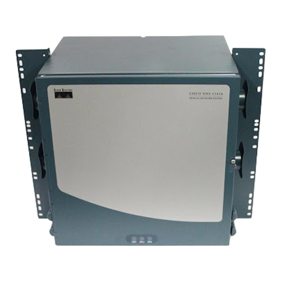
- Page 5 (EIA) standard and Telcordia-standard racks. The shelf assembly is a total of 17 inches (431.8 mm) wide with no mounting ears attached. Ring runs are not provided by Cisco and might hinder side-by-side installation of shelves where space is limited.
- Page 6 (25.4 mm) for air flow. To ensure the mounting is secure, use two to four #12-24 mounting screws for each side of the shelf assembly. Figure 1-2 shows the rack mounting position for the ONS 15454. Figure 1-1: Cisco ONS 15454 ANSI Dimensions...
-
Page 7: Figure 1-2: Mounting An Ons 15454 In A Rack
ONS 15454 Bay Assembly The Cisco ONS 15454 bay assembly simplifies ordering and installing the ONS 15454 because it allows you to order shelf assemblies preinstalled in a seven-foot (2.133 m) rack. The bay assembly is available in a three- or four-shelf configuration. -
Page 8: Front Door
The ONS 15454 ships with a standard door but can also accommodate a deep door and extended fiber clips (15454-DOOR-KIT) to provide additional room for cabling (Figure 1-4). Figure 1-4: Cisco ONS 15454 Deep Door Figure 1-3: The ONS 15454 Front Door... -
Page 9: Figure 1-5: Ons 15454 Front Door Ground Strap
Before you remove the front door, you have to remove the ground strap of the front door (Figure 1-5). Figure 1-5: ONS 15454 Front Door Ground Strap Figure 1-4: Cisco ONS 15454 Deep Door... -
Page 10: Figure 1-6: Removing The Ons 15454 Front Door
ONS_15454_Reference_Manual_R8.5.x_--_Shelf_and_Backplane_Hardware Figure 1-6 shows how to remove the front door. Figure 1-6: Removing the ONS 15454 Front Door An erasable label is pasted on the inside of the front door (Figure 1-7). You can use the label to record slot assignments, port assignments, card types, node ID, rack ID, and serial number for the ONS 15454. -
Page 11: Figure 1-7: Front-Door Erasable Label
ONS_15454_Reference_Manual_R8.5.x_--_Shelf_and_Backplane_Hardware Figure 1-7: Front-Door Erasable Label Note: The front door label also includes the Class I and Class 1M laser warning (Figure 1-8). Figure 1-8: Laser Warning on the Front-Door Label Backplane Covers If a backplane does not have an EIA panel installed, it should have two sheet metal backplane covers (one on each side of the backplane) as shown in Figure 1-9. -
Page 12: Backplane Covers
ONS_15454_Reference_Manual_R8.5.x_--_Shelf_and_Backplane_Hardware Lower Backplane Cover The lower section of the ONS 15454 backplane is covered by either a clear plastic protector (15454-SA-ANSI) or a sheet metal cover (15454-SA-HD), which is held in place by five 6-32 x 1/2 inch screws. Remove the lower backplane cover to access the alarm interface panel (AIP), alarm pin fields, frame ground, and power terminals (Figure 1-10). -
Page 13: Figure 1-12: Installing The Plastic Rear Cover With Spacers
ONS_15454_Reference_Manual_R8.5.x_--_Shelf_and_Backplane_Hardware You can also install the optional spacers if more space is needed between the cables and rear cover (Figure 1-12). Figure 1-12: Installing the Plastic Rear Cover with Spacers Alarm Interface Panel The AIP is located above the alarm contacts on the lower section of the backplane. The AIP provides surge protection for the ONS 15454. -
Page 14: Alarm Interface Panel Replacement
Resetting the active TCC2/TCC2P card causes a service disruption of three to five minutes on all E-Series Ethernet traffic due to spanning tree reconvergence. Refer to the Cisco ONS 15454 Troubleshooting Guide for an AIP replacement procedure. -
Page 15: Electrical Interface Assemblies
ONS_15454_Reference_Manual_R8.5.x_--_Shelf_and_Backplane_Hardware forth). As you face the rear of the ONS 15454 shelf assembly, the right side is the A side and the left side is the B side. The top of the EIA connector columns are labeled with the corresponding slot number, and EIA connector pairs are marked transmit (Tx) and receive (Rx) to correspond to transmit and receive cables. -
Page 16: Table 1-2: Eia Configurations Compatible With The 15454-Sa-Ansi And The
ONS_15454_Reference_Manual_R8.5.x_--_Shelf_and_Backplane_Hardware Slot 5 Slot 16 Slot 6 Slot 17 Slot 1 Slot 12 Slot 2 Slot 13 6 AMP Slot 3 6 AMP Slot 14 DS-1 Champ 15454-EIA-AMP-A84= Champ 15454-EIA-AMP-B84= Champ connectors Slot 4 connectors Slot 15 Slot 5 Slot 16 Slot 6 Slot 17 Table 1-2 shows the EIA types supported by both the 15454-SA-ANSI and the 15454-SA-HD (high density) - Page 17 ONS_15454_Reference_Manual_R8.5.x_--_Shelf_and_Backplane_Hardware EC-1 Slot 3 Slot 14 DS3XM-6 Slot 4 Slot 15 DS3XM-12 Slot 5 Slot 16 Slot 6 Slot 17 Slot 1 Slot 12 Slot 2 Slot 13 6 AMP Slot 3 6 AMP Slot 14 DS-1 Champ 15454-EIA-1AMPA84= Champ 15454-EIA-1AMPB84= Champ connectors...
-
Page 18: Figure 1-13: Bnc Backplane For Use In 1:1 Protection Schemes
Figure 1-13 shows the ONS 15454 with preinstalled BNC EIAs. To install coaxial cable with BNC connectors, refer to the "Install Shelf and Backplane Cable" chapter in the Cisco ONS 15454 Procedure Guide. Figure 1-13: BNC Backplane for Use in 1:1 Protection Schemes BNC Connectors The EIA side marked "A"... -
Page 19: Bnc Insertion And Removal Tool
ITT are also compatible). Use straight connectors on RG-59/U cable to connect to the high-density BNC EIA. Cisco recommends these cables for connection to a patch panel; they are designed for long runs. You can use high-density BNC EIAs for DS-3 (including the DS3XM-6 and DS3XM-12) or EC-1 cards. Figure 1-15 shows the ONS 15454 with preinstalled high-density BNC EIAs. - Page 20 ONS_15454_Reference_Manual_R8.5.x_--_Shelf_and_Backplane_Hardware The EIA side marked "A" hosts 48 pairs of BNC connectors. Each column of connector pairs is numbered and corresponds to the slot of the same number. The first column (12 pairs) of BNC connectors corresponds to Slot 1 on the shelf assembly, the second column to Slot 2, the third column to Slot 4, and the fourth column to Slot 5.
-
Page 21: Table 1-3: Minibnc Protection Types And Slots
Figure 1-16 shows the ONS 15454 with preinstalled MiniBNC EIAs. To install coaxial cable with MiniBNC connectors, refer to the "Install the Shelf and Backplane Cable" chapter in the Cisco ONS 15454 Procedure Guide. Figure 1-16: MiniBNC Backplane for Use in 1:N Protection Schemes... -
Page 22: Table 1-4: J-Labeling Port Assignments For A Shelf Assembly
ONS_15454_Reference_Manual_R8.5.x_--_Shelf_and_Backplane_Hardware Table 1-4 and Table 1-5 show the J-labeling and corresponding card ports for a shelf assembly configured with low-density electrical cards. Table 1-4: J-Labeling Port Assignments for a Shelf Assembly Configure with Low-Density Electrical Cards (A Side) Slot Port Type TX J4 T13 T25 T37 T1 T13 T25 T37 T14 T26 T38 T2... -
Page 23: Table 1-6: J-Labeling Port Assignments For A Shelf Configured With
ONS_15454_Reference_Manual_R8.5.x_--_Shelf_and_Backplane_Hardware T17 T29 T41 T5 T17 T29 T41 T18 T30 T42 T6 T18 T30 T42 T19 T31 T43 T7 T19 T31 T43 T20 T32 T44 T8 T20 T32 T44 T21 T33 T45 T9 T21 T33 T45 T10 T22 T34 T46 T10 T22 T34 T46 T11 T23 T35 T47 T11 T23 T35 T47 T12 T24 T36 T48 T12 T24 T36 T48 RX J28... -
Page 24: Table 1-7: J-Labeling Port Assignments For A Shelf Configured With
ONS_15454_Reference_Manual_R8.5.x_--_Shelf_and_Backplane_Hardware T12 T24 T12 T24 RX J12 R13 R25 R37 R1 R13 R25 R37 R14 R26 R38 R2 R14 R26 R38 R15 R27 R39 R3 R15 R27 R39 R16 R28 R40 R4 R16 R28 R40 R17 R29 R41 R5 R17 R29 R41 R18 R30 R42 R6 R18 R30 R42 R19 R31 R43 R7... -
Page 25: Figure 1-17: Minibnc Insertion And Removal Tool
AMP 415484-2 (75-ohm) connectors. Use RG-179/U cable to connect to the ONS 15454 EIA. Cisco recommends these cables for connection to a patch panel; they are not designed for long runs. Range does not affect loopback testing. -
Page 26: Figure 1-18: Smb Eia Backplane
The ONS 15454 AMP Champ EIA supports 64-pin (32 pair) AMP Champ connectors for each slot on both sides of the shelf assembly where the EIA is installed. Cisco AMP Champ connectors are female AMP # 552246-1 with AMP # 552562-2 bail locks. Each AMP Champ connector supports 14 DS-1 ports. You can use AMP Champ EIAs with DS-1 cards only. -
Page 27: Figure 1-19: Amp Champ Eia Backplane
ONS_15454_Reference_Manual_R8.5.x_--_Shelf_and_Backplane_Hardware Because each DS1-14 card supports 14 DS-1 ports, only 56 pins (28 pairs) of the 64-pin connector are used. Prepare one 56-wire cable for each DS-1 facility installed. Figure 1-19: AMP Champ EIA Backplane Table 1-8 shows the pin assignments for the AMP Champ connectors on the ONS 15454 AMP Champ EIA. The EIA side marked "A"... -
Page 28: Table 1-9: Amp Champ Connector Pin Assignments (Shielded Ds-1 Cable
ONS_15454_Reference_Manual_R8.5.x_--_Shelf_and_Backplane_Hardware Tx Ring 3 Rx Tip 3 Rx Ring 3 Tx Tip 3 white/green 3 19 51 green/white yellow/brown brown/yellow Tx Tip 4 Tx Ring 4 Rx Tip 4 yellow/slate 20 52 Rx Ring 4 slate/yellow white/brown brown/white Tx Tip 5 white/slate 5 37 Tx Ring 5 slate/white Rx Tip 5 violet/blue 21 53 Rx Ring 5 blue/violet Rx Tip 6 Rx Ring 6... -
Page 29: Ubic-V Eia
ONS_15454_Reference_Manual_R8.5.x_--_Shelf_and_Backplane_Hardware Tx Tip 14 Tx Ring 14 Rx Tip 14 Rx Ring 14 black/brown brown/black black/brown brown/black Tx Tip 15 black/slate 15 47 Tx Tip 15 slate/black Rx Tip 15 black/slate 31 63 Rx Tip 15 slate/black Tx Tip 16 Rx Tip 16 16 48 Tx Tip 16 blue/yellow 32 64 Rx Tip 16 blue/yellow... - Page 30 ONS_15454_Reference_Manual_R8.5.x_--_Shelf_and_Backplane_Hardware The UBIC-V sheet metal covers use the same screw holes as the standard sheet metal covers, but they have 12 additional holes for pan-head screws and three holes for jack screws, so you can screw down the cover and the board using standoffs on the UBIC-V board. When installed with the standard door and cabling on the backplane, the ONS 15454 shelf measures approximately 15.7 inches (399 mm) deep when partially populated with backplane cables, 16.1 inches (409 mm) deep when fully populated, and 16.75 inches (425 mm) deep with the rear cover installed.
-
Page 31: Table 1-10: Ubic-V Protection Types And Slots
ONS_15454_Reference_Manual_R8.5.x_--_Shelf_and_Backplane_Hardware The A and B sides each host 16 high-density, 50-pin SCSI connectors. The A-side maps to Slots 1 through 6 and the B-side maps to Slots 12 through 17. In Software Releases 4.1.x and 4.6, UBIC-Vs support unprotected, 1:1, and 1:N (N 5) protection groups. In Software R5.0 and later, UBIC-Vs also support available high-density cards in unprotected and 1:N (N 2) protection groups. -
Page 32: Table 1-11: J-Labeling Port Assignments For A Shelf Assembly Configured
ONS_15454_Reference_Manual_R8.5.x_--_Shelf_and_Backplane_Hardware Tables 1-11 and 1-12 show the J-labeling and corresponding card ports for a shelf assembly configured with low-density electrical cards. Table 1-11: J-Labeling Port Assignments for a Shelf Assembly Configured with Low-Density Electrical Cards (A Side) Slot Port Type TX J4 RX J12 Ports Ports Ports Ports Ports Ports Ports Ports DS-1... - Page 33 ONS_15454_Reference_Manual_R8.5.x_--_Shelf_and_Backplane_Hardware DS-1 1-14 - DS-3 1-12 - DS-1 1-14 - DS-3 1-12 - DS-1 1-14 - DS-3 1-12 - DS-1 1-14 - DS-3 1-12 - DS-1 1-14 - DS-3 1-12 - DS-1 1-14 - DS-3 1-12 - Tables 1-13 and 1-14 show the J-labeling and corresponding card ports for a shelf assembly configured with high-density 48-port DS-3/EC-1 or 56-port DS-1 electrical cards.
-
Page 34: Eia Replacement
ONS_15454_Reference_Manual_R8.5.x_--_Shelf_and_Backplane_Hardware • DS3-12, DS3N-12 DS3-12E, DS3N-12E • • EC1-12 • DS3XM-6 • DS3XM-12 • DS3/EC1-48 DS1/E1-56 • The A and B sides each host 16 high-density, 50-pin SCSI connectors. The A-side maps to Slots 1 through 6 and the B-side maps to Slots 12 through 17. In Software Releases prior to Release 5.0, UBIC-Hs support unprotected, 1:1, and 1:N (where N 5) protection groups. -
Page 35: Ds-1 Cable
ONS_15454_Reference_Manual_R8.5.x_--_Shelf_and_Backplane_Hardware facility to be installed. Caution! Always use the supplied ESD wristband when working with a powered ONS 15454. Plug the wristband cable into the ESD jack located on the lower-right outside edge of the shelf assembly. If you use DS-1 electrical twisted-pair cables, equip the ONS 15454 with an SMB EIA on each side of the backplane where DS-1 cables will terminate. -
Page 36: Ubic-V Cables
ONS_15454_Reference_Manual_R8.5.x_--_Shelf_and_Backplane_Hardware • DS-1 cable, 150 feet: 15454-CADS1-SD • DS-1 cable, 250 feet: 15454-CADS1-ID • DS-1 cable, 655 feet: 15454-CADS1-LD • DS-3/EC-1 cable, 75 feet: 15454-CADS3-SD • DS-3/EC-1 cable, 225 feet: 15454-CADS3-ID • DS-3/EC-1 cable, 450 feet: 15454-CADS3-LD Figure 1-23 shows the pin locations on the DS-1 and DS-3/EC-1 SCSI connectors. Figure 1-23: Cable Connector Pins Table 1-16 shows the UBIC-V SCSI connector pin assignments for the DS-1 and DS-3/EC-1 cables. -
Page 37: Table 1-17: Ubic-V Eia Ds-1 Wiring
350 feet: 15454-CADS1-H-350 • 450 feet: 15454-CADS1-H-450 DS-3/EC-1 cables for the UBIC-H have a maximum supported distance of 450 feet. The following DS-3/EC-1 cables are available from Cisco Systems for use with the UBIC-H EIA: • 75 feet: 15454-CADS3-SD •... -
Page 38: Figure 1-24: Cable Connector Pins
ONS_15454_Reference_Manual_R8.5.x_--_Shelf_and_Backplane_Hardware Figure 1-24: Cable Connector Pins Table 1-18 shows the UBIC-H SCSI connector pin assignments for the DS-1 and DS-3/EC-1 cables. Table 1-18: UBIC-H DS-1 and DS-3/EC-1 Pin Assignments Pin Cable Port Pin Cable Port 26 7 FGnd 27 FGnd FGnd 28 FGnd FGnd... -
Page 39: Ethernet Cables
ONS_15454_Reference_Manual_R8.5.x_--_Shelf_and_Backplane_Hardware Tip Port 3 White/green Ring Port 3 Green/white Tip Port 4 White/brown Ring Port 4 Brown/white Tip Port 5 White/slate Ring Port 5 Slate/white Tip Port 6 Red/blue Ring Port 6 Blue/red Tip Port 7 Red/orange Ring Port 7 Orange/red Tip Port 8 Red/green Ring Port 8 Green/red Tip Port 9 Red/brown... -
Page 40: Figure 1-26: Straight-Through Cable
ONS_15454_Reference_Manual_R8.5.x_--_Shelf_and_Backplane_Hardware Figure 1-26 shows the straight-through Ethernet cable schematic. Use a straight-through cable when connecting to a router or a PC. Figure 1-26: Straight-Through Cable Figure 1.27 shows the crossover Ethernet cable schematic. Use a crossover cable when connecting to a switch or hub. -
Page 41: Figure 1-28: Managing Cables On The Front Panel
ONS_15454_Reference_Manual_R8.5.x_--_Shelf_and_Backplane_Hardware Figure 1-28: Managing Cables on the Front Panel Fiber Management The jumper routing fins are designed to route fiber jumpers out of both sides of the shelf. Slots 1 to 6 exit to the left, and Slots 12 to 17 exit to the right. Figure 1-29 shows fibers routed from cards in the left slots, down through the fins, then exiting out the fiber channel to the left. -
Page 42: Table 1-21: Fiber Channel Capacity (One Side Of The Shelf
ONS_15454_Reference_Manual_R8.5.x_--_Shelf_and_Backplane_Hardware Table 1-21: Fiber Channel Capacity (One Side of the Shelf) Maximum Number of Fibers Exiting Each Side Fiber Diameter No Ethernet Cables One Ethernet Cable Two Ethernet Cables 1.6 mm (0.6 inch) 144 2 mm (0.7 inch) 3 mm (0.11 inch) 40 Plan your fiber size according to the number of cards/ports installed in each side of the shelf. -
Page 43: Alarm Expansion Panel
ONS_15454_Reference_Manual_R8.5.x_--_Shelf_and_Backplane_Hardware 23-inch (584.2 mm) rack, two additional inches (50.8 mm) of cable management area is available on each side of the shelf assembly. Alarm Expansion Panel The optional ONS 15454 alarm expansion panel (AEP) can be used with the Alarm Interface Controller-International card (AIC-I) card to provide an additional 48 dry alarm contacts for the ONS 15454, 32 of which are inputs and 16 are outputs. -
Page 44: Wire-Wrap And Pin Connections
ONS_15454_Reference_Manual_R8.5.x_--_Shelf_and_Backplane_Hardware Each AEP alarm input port has provisionable label and severity. The alarm inputs have optocoupler isolation. They have one common 48-VDC output and a maximum of 2 mA per input. Each opto metal oxide semiconductor (MOS) alarm output can operate by definable alarm condition, a maximum open circuit voltage of 60 VDC, anda maximum current of 100 mA. -
Page 45: Figure 1-34: Alarm Input Circuit Diagram
ONS_15454_Reference_Manual_R8.5.x_--_Shelf_and_Backplane_Hardware Orange AE_DIN_N AE_DOUT_N AE_DOUT_P AE_DIN_P Brown AE_DOUT_N AE_DIN_N Figure 1-34 is a circuit diagram of the alarm inputs (Inputs 1 and 32 are shown in the example). Figure 1-34: Alarm Input Circuit Diagram Table 1-23 lists the connections to the external alarm sources. Table 1-23: Alarm Input Pin Association AMP Champ Pin Number Signal Name... -
Page 46: Figure 1-35: Alarm Output Circuit Diagram
ONS_15454_Reference_Manual_R8.5.x_--_Shelf_and_Backplane_Hardware ALARM_IN_26- ALARM_IN_27- 47 ALARM_IN_28- ALARM_IN_29- 48 ALARM_IN_30- ALARM_IN_31- 50 N.C. ALARM_IN_+ GND1 ALARM_IN_0- 52 GND2 Figure 1-35 is a circuit diagram of the alarm outputs (Outputs 1 and 16 are shown in the example). Figure 1-35: Alarm Output Circuit Diagram Use the pin numbers in Table 1-24 to connect to the external elements being switched by external alarms. - Page 47 Filler Card Filler cards are designed to occupy empty multiservice and AIC-I slots in the Cisco ONS 15454 (Slots 1-6, 9, and 12 - 17). The filler card cannot operate in the XC slots (Slots 8 and 10) or TCC slots (7 and 11). When installed, the filler card aids in maintaining proper air flow and EMI requirements.
- Page 48 ONS_15454_Reference_Manual_R8.5.x_--_Shelf_and_Backplane_Hardware Fan-Tray Assembly The fan-tray assembly is located at the bottom of the ONS 15454 bay assembly. The fan tray is a removable drawer that holds fans and fan-control circuitry for the ONS 15454. The front door can be left in place or removed before installing the fan-tray assembly.
- Page 49 The red Fan Fail LED on the front of the fan tray illuminates when one or more fans fail. For fan tray replacement instructions, refer to the Cisco ONS 15454 Troubleshooting Guide. The red Fan Fail LED clears after you install a working fan tray.
- Page 50 [0.1018 inch]), with an integral lock washer. The lug must be a dual-hole type and rated to accept the #6 AWG (4.115 mm² [0.162 inch]) cable. Two posts are provided on the Cisco ONS 15454 to accommodate the Pilot Fuse...
- Page 51 ONS_15454_Reference_Manual_R8.5.x_--_Shelf_and_Backplane_Hardware dual-hole lug. Figure 1-37 shows the location of the ground posts. Figure 1-37: Ground Posts on the ONS 15454 Backplane Alarm, Timing, LAN, and Craft Pin Connections Caution! Always use the supplied ESD wristband when working with a powered ONS 15454. Plug the wristband cable into the ESD jack located on the lower-right outside edge of the shelf assembly.
- Page 52 ONS_15454_Reference_Manual_R8.5.x_--_Shelf_and_Backplane_Hardware Figure 1-39: ONS 15454 Backplane Pinouts Figure 1-38: ONS 15454 Backplane Pinouts (Release 3.4 or Later)
- Page 53 ONS_15454_Reference_Manual_R8.5.x_--_Shelf_and_Backplane_Hardware Alarm Contact Connections The alarm pin field supports up to 17 alarm contacts, including four audible alarms, four visual alarms, one alarm cutoff (ACO), and four user-definable alarm input and output contacts. Audible alarm contacts are in the LOCAL ALARM AUD pin field and visual contacts are in the LOCAL ALARM VIS pin field.
- Page 54 Backplane RJ-45 Pin Field Pins Pins LAN 1 Connecting to data circuit-terminating equipment (DCE , a hub or switch) LAN 1 Connecting to data terminal equipment (DTE) (a PC/workstation or router) 1 The Cisco ONS 15454 is DCE. Timing Connections...
- Page 55 ONS_15454_Reference_Manual_R8.5.x_--_Shelf_and_Backplane_Hardware TL1 Craft Interface Installation You can use the craft pins on the ONS 15454 backplane or the EIA/TIA-232 port on the TCC2/TCC2P card faceplate to create a VT100 emulation window to serve as a TL1 craft interface to the ONS 15454. Use a straight-through cable to connect to the EIA/TIA-232 port.
- Page 56 ONS_15454_Reference_Manual_R8.5.x_--_Shelf_and_Backplane_Hardware Card Slot Requirements The ONS 15454 shelf assembly has 17 card slots numbered sequentially from left to right. Slots 1 to 6 and 12 to 17 are multiservice slots that are used for electrical, optical, and Ethernet cards (traffic cards). Card compatibility depends on the EIA, protection scheme, and cross-connect card type used in the shelf.
- Page 57 ONS_15454_Reference_Manual_R8.5.x_--_Shelf_and_Backplane_Hardware connector SMB w/wire wrap DS1N-14 1.544 Mbps adapter, AMP Champ connector SMB w/wire wrap DS1/E1-56 1.544 Mbps adapter, AMP Champ connector DS3-12 44.736 Mbps SMB or BNC1 Backplane DS3N-12 44.736 Mbps SMB or BNC1 DS3-12E 44.736 Mbps SMB or BNC1 Backplane DS3N-12E 44.736 Mbps...
- Page 58 To replace a card with a card of a different type, physically remove the card and replace it with the new card, then delete the original card from CTC. For specifics, refer to the "Install Cards and Fiber-Optic Cable" chapter in the Cisco ONS 15454 Procedure Guide.
- Page 59 ONS_15454_Reference_Manual_R8.5.x_--_Shelf_and_Backplane_Hardware Table 1-31: ONS 15454 Software and Hardware Compatibility-XC and XCVT Configurations Shelf Hardware 4.6.0x (4.6) 5.0.0x (5.0) 6.0.0x (6.0) 7.0.0x (7.0) 7.2.0x (7.2) 8.0.0x (8.0) 8.5.0x (8 Assembly Fully Fully Fully Fully Fully Fully Fully TCC2 compatible compatible compatible compatible compatible compatible...
- Page 60 ONS_15454_Reference_Manual_R8.5.x_--_Shelf_and_Backplane_Hardware Fully Fully Fully Fully Fully Fully Fully compatible compatible compatible compatible compatible compatible compatib Fully Fully Fully Fully Fully Fully Fully ML1000-2 compatible compatible compatible compatible compatible compatible compatib Fully Fully Fully Fully Fully ML100X-8 supported supported compatible compatible compatible compatible compatib...
- Page 61 1. The XC card does not support features new to Release 5.0 and greater. 2. The shelf assemblies supported are 15454-SA-HD, 15454-SA-ANSI, and 15454-NEBS3E. 3. DS3 card having the part number 87-31-0001 does not work in Cisco ONS 15454 R8.0 and later. 4. ML-MR-10 and CE-MR-10 cards are not supported on XCVT.
- Page 62 ONS_15454_Reference_Manual_R8.5.x_--_Shelf_and_Backplane_Hardware Fully Fully Fully Fully Fully Fully Fully compatible compatible compatible compatible compatible compatible compatible Fully Fully Fully Fully Fully Fully Fully AIC-I compatible compatible compatible compatible compatible compatible compatible Fully Fully Fully Fully Fully Fully Fully DS1-14 compatible compatible compatible compatible compatible...
- Page 63 ONS_15454_Reference_Manual_R8.5.x_--_Shelf_and_Backplane_Hardware Fully Fully Fully Fully Fully Fully Fully compatible compatible compatible compatible compatible compatible compatible Fully Fully Fully Fully Fully Fully Fully ML1000-2 compatible compatible compatible compatible compatible compatible compatible Fully Fully Fully Fully Fully ML100X-8 supported supported compatible compatible compatible compatible compatible...
- Page 64 1. The shelf assemblies supported are 15454-SA-HD, 15454-SA-ANSI, and 15454-NEBS3E. 2. DS3 card having the part number 87-31-0001 does not work in Cisco ONS 15454 R8.0 and later. 3. Slots 1 to 4 and 14 to 17 give a total bandwidth of up to 2.5 Gb/s. Slots 5, 6, 12 , and 13 give a total bandwidth of up to 10 Gb/s 4.
Need help?
Do you have a question about the ONS 15454 Series and is the answer not in the manual?
Questions and answers