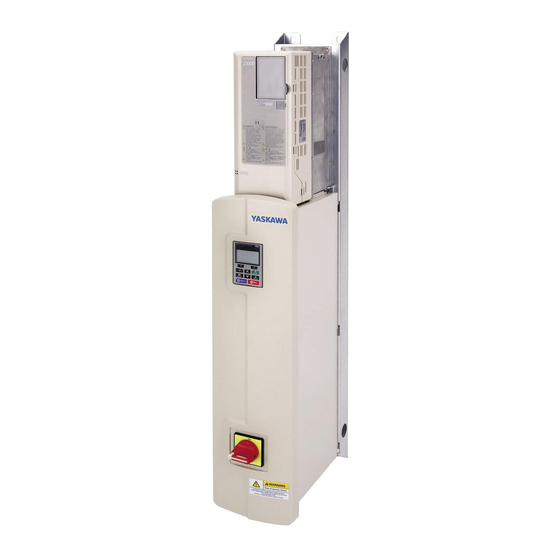
YASKAWA Z1000 Technical Manual
Ac drive bypass for hvac fans and pumps
208 v: 1/2 to 100 hp
480 v: 3/4 to 250 hp
Hide thumbs
Also See for Z1000:
- User manual (400 pages) ,
- Programming manual (340 pages) ,
- Quick start manual (92 pages)
Table of Contents
Advertisement
Quick Links
YASKAWA AC Drive Z1000
AC Drive Bypass for HVAC Fans and Pumps
Technical Manual
Type: Z1B1
Models: 208 V: 1/2 to 100 HP
480 V: 3/4 to 250 HP
To properly use the product, read this manual thoroughly and retain
for easy reference, inspection, and maintenance. Ensure the end user
receives this manual.
MANUAL NO. SIEP YAIZ1B 01E
1
Receiving
2
Mechanical Installation
3
Electrical Installation
4
Start-Up Programming &
Operation
5
Programming
6
Diagnostics &
Troubleshooting
7
Periodic Inspection &
Maintenance
A
Specifications
B
Parameter List
C
BACnet Communications
D
MEMOBUS/Modbus
Communications
E
Apogee FLN Network
Protocol
F
Metasys N2 Network
Protocol
G
Standards Compliance
H
Quick Reference Sheet
Advertisement
Table of Contents
Troubleshooting

Related Manuals for YASKAWA Z1000


Summary of Contents for YASKAWA Z1000
- Page 1 YASKAWA AC Drive Z1000 AC Drive Bypass for HVAC Fans and Pumps Technical Manual Type: Z1B1 Models: 208 V: 1/2 to 100 HP 480 V: 3/4 to 250 HP To properly use the product, read this manual thoroughly and retain for easy reference, inspection, and maintenance.
- Page 2 Every precaution has been taken in the preparation of this manual. Yaskawa assumes no responsibility for errors or omissions. Neither is any liability assumed for damages resulting from the use of the information contained in this publication.
-
Page 3: Table Of Contents
2. MECHANICAL INSTALLATION..............37 2.1 Section Safety......................38 2.2 Mechanical Installation ..................... 40 Installation Environment ......................40 Installation Orientation and Spacing..................41 Exterior and Mounting Dimensions ..................42 YASKAWA ELECTRIC SIEP YAIZ1B 01E YASKAWA AC Drive – Z1000 Bypass Technical Manual... - Page 4 Verifying Parameter Changes: Modified Constants ................ 100 Simplified Setup Using the Quick Setting Group................101 4.4 Powering Up the Drive ......................103 Powering Up the Drive and Operation Status Display..............103 YASKAWA ELECTRIC SIEP YAIZ1B 01E YASKAWA AC Drive – Z1000 Bypass Technical Manual...
- Page 5 H4: Multi-Function Analog Outputs ....................165 H5: MEMOBUS/Modbus Serial Communication ................167 5.9 L: Protection Functions ....................168 L1: Motor Protection ........................168 L2: Momentary Power Loss Ride-Thru.................... 169 YASKAWA ELECTRIC SIEP YAIZ1B 01E YASKAWA AC Drive – Z1000 Bypass Technical Manual...
- Page 6 Programming Error Codes, Causes, and Possible Solutions............251 6.7 Auto-Tuning Fault Detection ....................254 Auto-Tuning Codes, Causes, and Possible Solutions..............254 6.8 Diagnosing and Resetting Faults..................256 Fault Occurs Simultaneously with Power Loss ................256 YASKAWA ELECTRIC SIEP YAIZ1B 01E YASKAWA AC Drive – Z1000 Bypass Technical Manual...
- Page 7 Three-Phase 480 Vac Models Z1B1B001 to B034 ................. 302 Three-Phase 480 Vac Models Z1B1B040 to B302 ................. 303 A.2 Drive Specifications ......................304 A.3 Drive Watt Loss Data ......................306 YASKAWA ELECTRIC SIEP YAIZ1B 01E YASKAWA AC Drive – Z1000 Bypass Technical Manual...
- Page 8 L2: Momentary Power Loss Ride-Thru.................... 328 L3: Stall Prevention ......................... 328 L4: Speed Detection........................329 L5: Fault Restart..........................329 L6: Torque Detection........................330 L8: Drive Protection......................... 330 B.10 n: Special Adjustment.......................331 YASKAWA ELECTRIC SIEP YAIZ1B 01E YASKAWA AC Drive – Z1000 Bypass Technical Manual...
- Page 9 Binary Input Objects ........................370 Binary Output Objects ........................370 Binary Value Objects........................371 Device Object ..........................373 C.7 Accessing Bypass Parameters and the Enter Command ..........374 YASKAWA ELECTRIC SIEP YAIZ1B 01E YASKAWA AC Drive – Z1000 Bypass Technical Manual...
- Page 10 E. APOGEE FLN NETWORK PROTOCOL.............. 407 E.1 APOGEE FLN Set-Up......................408 Z1000 Bypass Parameter Settings for APOGEE FLN Communications......... 408 E.2 Connecting to a Network ....................409 Network Cable Connection......................409 YASKAWA ELECTRIC SIEP YAIZ1B 01E YASKAWA AC Drive – Z1000 Bypass Technical Manual...
- Page 11 G.1 Section Safety........................440 G.2 European Standards ......................442 CE Low Voltage Directive Compliance.................... 442 EMC Guidelines Compliance ......................442 G.3 UL/cUL Standards ......................443 UL Standards Compliance ......................443 YASKAWA ELECTRIC SIEP YAIZ1B 01E YASKAWA AC Drive – Z1000 Bypass Technical Manual...
- Page 12 Motor Setup............................. 447 Multi-Function Digital Inputs ......................447 Analog Inputs ..........................448 Multi-Function Digital Outputs ......................448 Monitor Outputs..........................448 H.3 User Setting Table ......................449 INDEX ........................455 YASKAWA ELECTRIC SIEP YAIZ1B 01E YASKAWA AC Drive – Z1000 Bypass Technical Manual...
-
Page 13: Preface & General Safety
Preface & General Safety This section provides safety messages pertinent to this product that, if not heeded, may result in fatality, personal injury, or equipment damage. Yaskawa is not responsible for the consequences of ignoring these instructions. PREFACE.......................14 GENERAL SAFETY....................16... -
Page 14: Preface
It also gives detailed information on fault diagnostics, parameter settings, and BACnet specifications. The purpose of this manual is to prepare the Z1000 Bypass for a trial run with an application and for basic operation. This manual is also available for download on the Yaskawa documentation website, www.yaskawa.com. -
Page 15: Symbols
• Modbus®, trademark of Schneider Automation, Inc. • LONWORKS®, trademark of Echelon Corporation • Other companies and product names mentioned in this manual are trademarks of those companies. YASKAWA ELECTRIC SIEP YAIZ1B 01E YASKAWA AC Drive – Z1000 Bypass Technical Manual... -
Page 16: General Safety
• When ordering a new copy of the manual due to damage or loss, contact your Yaskawa representative or the nearest Yaskawa sales office and provide the manual number shown on the front cover. -
Page 17: Safety Messages
The Z1000 Bypass is suitable for use on a circuit capable of delivering not more than 100,000 RMS symmetrical amperes, 208 Vac and 480 Vac with the circuit breaker option or when protected by class J or class L fuses as specified on the Z1000 Bypass nameplate. -
Page 18: General Application Precautions
NOTICE: The drive is capable of running the motor up to 240 Hz. Be sure to set the upper limit for the frequency of the drive to prevent the possible danger of accidentally operating equipment at higher than rated speed. The default setting for the maximum output frequency is 60 Hz. YASKAWA ELECTRIC SIEP YAIZ1B 01E YASKAWA AC Drive – Z1000 Bypass Technical Manual... -
Page 19: Motor Application Precautions
Explosion-Proof Motor The motor and the drive must be tested together to be certified as explosion-proof. The drive is not designed for explosion- proof areas. YASKAWA ELECTRIC SIEP YAIZ1B 01E YASKAWA AC Drive – Z1000 Bypass Technical Manual... -
Page 20: Drive Label Warning Example
5 minutes before inspecting, performing maintenance or wiring the drive. Hot surfaces Top and Side surfaces may ● become hot. Do not touch. Figure i.1 Warning Information Example YASKAWA ELECTRIC SIEP YAIZ1B 01E YASKAWA AC Drive – Z1000 Bypass Technical Manual... -
Page 21: Bypass Label Warning Example
Bypass Label Warning Example Always heed the warning information listed in Figure i.3 Figure i.4 in the positions shown in Figure i.2. Figure i.3 Warning Information Example A YASKAWA ELECTRIC SIEP YAIZ1B 01E YASKAWA AC Drive – Z1000 Bypass Technical Manual... - Page 22 General Safety Figure i.4 Warning Information Example B Warning Label A (inside enclosure) Warning Label B Figure i.5 Bypass Warning Label Locations YASKAWA ELECTRIC SIEP YAIZ1B 01E YASKAWA AC Drive – Z1000 Bypass Technical Manual...
-
Page 23: Warranty Information
Customers are responsible for periodic inspections of the drive. Upon request, a Yaskawa representative will inspect the drive for a fee. If the Yaskawa representative finds the drive to be defective due to Yaskawa workmanship or materials and the defect occurs during the warranty period, this inspection fee will be waived and the problem remedied free of charge. - Page 24 General Safety This Page Intentionally Blank YASKAWA ELECTRIC SIEP YAIZ1B 01E YASKAWA AC Drive – Z1000 Bypass Technical Manual...
-
Page 25: Receiving
Receiving This chapter explains how to inspect the Z1000 Bypass upon receipt, and gives an overview of the different enclosure types and components. SECTION SAFETY....................26 GENERAL DESCRIPTION..................27 MODEL NUMBERS AND NAMEPLATE CHECKS..........28 BYPASS COMPONENT DESCRIPTIONS.............31 BYPASS COMPONENT NAMES................33 YASKAWA ELECTRIC SIEP YAIZ1B 01E YASKAWA AC Drive – Z1000 Bypass Technical Manual... -
Page 26: Section Safety
Ensure that the motor is suitable for drive duty and/or the motor service factor is adequate to accommodate the additional heating with the intended operating conditions. YASKAWA ELECTRIC SIEP YAIZ1B 01E YASKAWA AC Drive – Z1000 Bypass Technical Manual... -
Page 27: General Description
Kinetic Energy Buffering power loss and continue operation. Overexcitation Deceleration Provides fast deceleration without using a braking resistor. Prevents overvoltage by increasing speed during Overvoltage Suppression regeneration. YASKAWA ELECTRIC SIEP YAIZ1B 01E YASKAWA AC Drive – Z1000 Bypass Technical Manual... -
Page 28: Model Numbers And Nameplate Checks
Z1000 Bypass storage must be in a clean and dry location. Maintain the factory packaging and provide covering as needed to protect the Z1000 Bypass from construction site dirt, water, debris and traffic prior to and during construction. -
Page 29: Bypass Nameplate
1.3 Model Numbers and Nameplate Checks Bypass Nameplate The nameplate is located on the inside right wall of the Z1000 Bypass enclosure. The nameplate shown below is an example for a standard Z1000 Bypass. A.C. INPUT Volts: 208 Hz: 50/60 Phase: 3 Amps: 2.9... -
Page 30: Bypass Enclosures
DD.Z1.1.F1.01 Bypass Enclosures All Z1000 Bypass units are intended for non-hazardous locations. All Z1000 Bypass units are NEMA Type 1 Enclosures and are constructed for indoor use to provide a degree of protection against incidental contact with enclosed electrical equipment and falling dust or dirt. -
Page 31: Bypass Component Descriptions
Figure 1.4 Disconnect Handle Shown in the OFF position Contactors The Z1000 Bypass is a 2-contactor or 3-contactor bypass circuit employing IEC rated contactors in an electrically interlocked arrangement to allow mutually exclusive operation in Drive or Bypass modes. The control logic and “soft start” characteristic of the drive limit the drive input and output contactors to motor FLA current or less. - Page 32 Control Power Transformer A Control Power Transformer (CPT) is provided to power the Z1000 Bypass 120 Vac control circuit. The VA capacity is determined by the control circuit and optional functions specified for the unit. The CPT primary is fused in both legs, the secondary is fused when required by NEC (transformer VA and wire size dependent).
-
Page 33: Bypass Component Names
1.5 Bypass Component Names Bypass Component Names This section gives an overview of the Z1000 Bypass components described in this manual. Note: Refer to Using the HOA Keypad on page 91 for a description of the HOA keypad. 208 Vac Z1B1D002 to D074 480 Vac Z1B1B001 to B077 A –... - Page 34 E – Fan mounting screws K – Z1000 drive F – Z1000 drive digital operator blank L – Bypass enclosure cover Figure 1.6 Exploded View of Components (Z1B1D088) YASKAWA ELECTRIC SIEP YAIZ1B 01E YASKAWA AC Drive – Z1000 Bypass Technical Manual...
-
Page 35: Front Views
F – EMC filter switch SW2 C – Jumper S5 G – EMC filter switch SW1 D – Terminal TB4 Figure 1.7 Front View of Z1000 Drives YASKAWA ELECTRIC SIEP YAIZ1B 01E YASKAWA AC Drive – Z1000 Bypass Technical Manual... - Page 36 F – 120 V control transformer M – Communications port CN2 G – Air filter N – Option B (Contactor K1) Figure 1.8 Front View of Bypass Units YASKAWA ELECTRIC SIEP YAIZ1B 01E YASKAWA AC Drive – Z1000 Bypass Technical Manual...
-
Page 37: Mechanical Installation
Mechanical Installation This chapter explains how to properly mount and install the Z1000 Bypass. SECTION SAFETY....................38 MECHANICAL INSTALLATION................40 YASKAWA ELECTRIC SIEP YAIZ1B 01E YASKAWA AC Drive – Z1000 Bypass Technical Manual... -
Page 38: Section Safety
If the motor is to be operated at a speed higher than the rated speed, consult with the manufacturer. Continuously operating an oil-lubricated motor in the low-speed range may result in burning. YASKAWA ELECTRIC SIEP YAIZ1B 01E YASKAWA AC Drive – Z1000 Bypass Technical Manual... - Page 39 Never lift or move the drive while the cover is removed. This can damage the terminal board and other components. YASKAWA ELECTRIC SIEP YAIZ1B 01E YASKAWA AC Drive – Z1000 Bypass Technical Manual...
-
Page 40: Mechanical Installation
Install the bypass vertically to maintain maximum cooling effects. NOTICE: Avoid placing peripheral devices, transformers, or other electronics near the Z1000 Bypass as the noise created can lead to erroneous operation. If such devices must be used in close proximity to the Bypass, take proper steps to shield the bypass from noise. -
Page 41: Installation Orientation And Spacing
A – 50 mm (2.0 in.) minimum C – 120 mm (4.7 in.) minimum B – 30 mm (1.2 in.) minimum D – Airflow direction Figure 2.2 Correct Installation Spacing YASKAWA ELECTRIC SIEP YAIZ1B 01E YASKAWA AC Drive – Z1000 Bypass Technical Manual... -
Page 42: Exterior And Mounting Dimensions
B011 B014 D024 B021 D030 B027 B034 D046 B040 D059 B52L B052 D074 B065 B077 D088 B096 D114 B124 D143 B156 D169 B180 D211 B240 D273 B302 YASKAWA ELECTRIC SIEP YAIZ1B 01E YASKAWA AC Drive – Z1000 Bypass Technical Manual... - Page 43 Removing the top protective cover from a NEMA Type 1 enclosure drive voids NEMA Type 1 protection. 1.00 0.44 Top Protective 4.72 Min. Cover on Drive 0.63 4.72 Min. 0.42 Recommended Ø1.25 Bottom Conduit Entrance Area Units = inches 2.07 YASKAWA ELECTRIC SIEP YAIZ1B 01E YASKAWA AC Drive – Z1000 Bypass Technical Manual...
- Page 44 16.44 11.65 9.89 51.69 35.50 14.17 14.20 12.52 128.0 <1> Removing the top protective cover from a NEMA Type 1 drive voids the NEMA Type 1 protection. YASKAWA ELECTRIC SIEP YAIZ1B 01E YASKAWA AC Drive – Z1000 Bypass Technical Manual...
- Page 45 2.2 Mechanical Installation 208 Vac (Z1B1D088 to D169) 480 Vac (Z1B1B096 to B180) Recommended Conduit Entrance Area Ø 0.53 Ø 2.00 5.00 min. 6.00 min. Units = inches YASKAWA ELECTRIC SIEP YAIZ1B 01E YASKAWA AC Drive – Z1000 Bypass Technical Manual...
- Page 46 20.87 25.09 23.49 27.49 1.05 47.26 36.85 7.70 19.03 6.14 3.39 370.0 B180 28.41 49.09 20.87 25.09 23.49 27.49 1.05 47.26 36.85 7.70 19.03 6.14 3.39 370.0 YASKAWA ELECTRIC SIEP YAIZ1B 01E YASKAWA AC Drive – Z1000 Bypass Technical Manual...
- Page 47 Door Open 6.00 min. 90˚ Ø 1.0 5.00 min. 35.27 19.75 Side Vent/ Closing Plate 9.24 23.10 33.94 39.51 Ø 0.625 18.63 10.87 34.50 Units = inches 37.50 YASKAWA ELECTRIC SIEP YAIZ1B 01E YASKAWA AC Drive – Z1000 Bypass Technical Manual...
- Page 48 Table 2.8 Bypass Model Enclosure Dimensions: 480 V Dimensions (in) Bypass Model Wt. (lb) Z1B1 B240 37.93 86.04 32.87 41.26 84.16 65.58 1050.0 B302 37.93 86.04 32.87 41.26 84.16 65.58 1050.0 YASKAWA ELECTRIC SIEP YAIZ1B 01E YASKAWA AC Drive – Z1000 Bypass Technical Manual...
-
Page 49: Electrical Installation
This chapter explains the proper procedures for wiring the control circuit terminals, motor, and power supply. SECTION SAFETY....................50 STANDARD CONNECTION DIAGRAM..............52 MAIN CIRCUIT WIRING..................56 INPUT AND OUTPUT POWER WIRING CONNECTIONS........61 CONTROL CIRCUIT WIRING................70 BYPASS AND DRIVE CONTROL I/O CONNECTIONS........85 EXTERNAL INTERLOCK..................86 YASKAWA ELECTRIC SIEP YAIZ1B 01E YASKAWA AC Drive – Z1000 Bypass Technical Manual... -
Page 50: Section Safety
Failure to comply could result in death or serious injury by fire. Do not install the drive to a combustible surface. Never place combustible materials on the drive. YASKAWA ELECTRIC SIEP YAIZ1B 01E YASKAWA AC Drive – Z1000 Bypass Technical Manual... - Page 51 Failure to comply could result in damage to the drive and will void warranty. Yaskawa is not responsible for any modification of the product made by the user. This product must not be modified. Check all the wiring to ensure that all connections are correct after installing the drive and connecting any other devices.
-
Page 52: Standard Connection Diagram
WARNING! Fire Hazard. Branch Circuit protection is required to be installed according to applicable local codes and the requirements listed on the Z1000 Bypass nameplate. Failure to comply could result in fire and damage to the bypass and drive or injury to personnel. The Z1000 Bypass is suitable for use on a circuit capable of delivering not more than 100,000 RMS symmetrical amperes, 208 Vac and 480 Vac with the circuit breaker option or when protected by class J or class L fuses as specified on the Z1000 Bypass nameplate. - Page 53 3.2 Standard Connection Diagram <7> <12> <9> <8> <1> <2> <3> <5> <6> <1> <10> <4> <10> <11> Figure 3.1 Z1000 Bypass Standard Connection Diagram YASKAWA ELECTRIC SIEP YAIZ1B 01E YASKAWA AC Drive – Z1000 Bypass Technical Manual...
- Page 55 <11> The motor overload relay is factory set for manual reset. Adjust the motor overload relay trip setting for the actual AC motor full load amps. <12> Secondary fuse F6 is added with control transformer T1 or a power rating 350 VA or greater. YASKAWA ELECTRIC SIEP YAIZ1B 01E YASKAWA AC Drive – Z1000 Bypass Technical Manual...
-
Page 56: Main Circuit Wiring
Models Z1B1D002 to D074 and Z1B1B001 to B077 Turn the disconnect handle to the “OFF” position. Figure 3.2 Disconnect Power Remove the two front cover screws using a #2 Phillips screwdriver. YASKAWA ELECTRIC SIEP YAIZ1B 01E YASKAWA AC Drive – Z1000 Bypass Technical Manual... - Page 57 3.3 Main Circuit Wiring Figure 3.3 Remove Screws Lift the cover up and gently pull forward to remove the front cover. Figure 3.4 Lift and Remove Cover YASKAWA ELECTRIC SIEP YAIZ1B 01E YASKAWA AC Drive – Z1000 Bypass Technical Manual...
- Page 58 Turn the flat head screw fasteners on the cover 1/2 turn counter-clockwise. Figure 3.6 Turn Fasteners Door will now swing open on hinges located on left side of the bypass. YASKAWA ELECTRIC SIEP YAIZ1B 01E YASKAWA AC Drive – Z1000 Bypass Technical Manual...
- Page 59 3.3 Main Circuit Wiring Figure 3.7 Swing Open Door YASKAWA ELECTRIC SIEP YAIZ1B 01E YASKAWA AC Drive – Z1000 Bypass Technical Manual...
-
Page 60: Bypass Main Circuit Terminal Block Configuration
Z1BVD088 to D169 Z1BVB001 to B077 Z1BVB096 to B180 T1 T2 T3 L1 L2 L3 L1 L2 L3 T1 T2 T3 Figure 3.8 Main Circuit Terminal Block Configuration YASKAWA ELECTRIC SIEP YAIZ1B 01E YASKAWA AC Drive – Z1000 Bypass Technical Manual... -
Page 61: Input And Output Power Wiring Connections
WARNING! Fire Hazard. Branch Circuit protection is required to be installed according to applicable local codes and the requirements listed on the Z1000 Bypass nameplate. Failure to comply could result in fire and damage to the bypass and drive or injury to personnel. The Z1000 Bypass is suitable for use on a circuit capable of delivering not more than 100,000 RMS symmetrical amperes, 208 Vac and 480 Vac with the circuit breaker option or when protected by class J or class L fuses as specified on the Z1000 Bypass nameplate. -
Page 62: Main Circuit Terminal Functions
D059 B065 – B077 8-3/0 – B096 D074 – 8-2/0 D088 – 8-3/0 D114 – 4-4/0 – B124 4-40 D143 B156 3/0-350 kcmil 3/0-350 kcmil D169 B180 YASKAWA ELECTRIC SIEP YAIZ1B 01E YASKAWA AC Drive – Z1000 Bypass Technical Manual... -
Page 63: Main Input Circuit And Motor Wiring
NOTICE: Do not connect phase-advancing capacitors or LC/RC noise filters to the output circuits. Failure to comply could result in damage to the drive, phase-advancing capacitors, LC/RC noise filters or ground fault circuit interrupters. YASKAWA ELECTRIC SIEP YAIZ1B 01E YASKAWA AC Drive – Z1000 Bypass Technical Manual... - Page 64 ) is connected to the enclosure. The enclosure ground lug must be connected to earth ground. See Figure Figure 3.9. The drive has a second ground lug to accept the motor ground lead. Figure 3.10 Ground Wiring for Multiple Bypass Units YASKAWA ELECTRIC SIEP YAIZ1B 01E YASKAWA AC Drive – Z1000 Bypass Technical Manual...
- Page 65 If EMC is a concern and the network is grounded symmetrically, install the SW1 and SW2 screws to the ON position. Installing the SW1 and SW2 screws enables the internal EMC filter (Drives are shipped with SW1/SW2 screws installed at the OFF position). Figure 3.11 Symmetrical Grounded Network YASKAWA ELECTRIC SIEP YAIZ1B 01E YASKAWA AC Drive – Z1000 Bypass Technical Manual...
- Page 66 Figure 3.14 EMC Filter Switch Location (Model Z1B1B124) A – SW1 (ON) C – SW2 (ON) B – Screw (OFF) Figure 3.15 EMC Filter Switch Location (Models Z1B1D143 to D273 and B156 to B240) YASKAWA ELECTRIC SIEP YAIZ1B 01E YASKAWA AC Drive – Z1000 Bypass Technical Manual...
-
Page 67: Wiring The Main Input Circuit
WARNING! Electrical Shock Hazard. Shut off the power supply to the drive before wiring the main circuit terminals. Failure to comply may result in death or serious injury. Wire the main circuit terminals after the terminal board has been properly grounded. YASKAWA ELECTRIC SIEP YAIZ1B 01E YASKAWA AC Drive – Z1000 Bypass Technical Manual... - Page 68 A – Control circuit wiring C – Motor output circuit B – Main input circuit Figure 3.17 Bypass Wire Routing Example (Models Z1B1D002 to D074 and B001 to B077) YASKAWA ELECTRIC SIEP YAIZ1B 01E YASKAWA AC Drive – Z1000 Bypass Technical Manual...
- Page 69 A – Control circuit wiring C – Main input circuit B – Motor output circuit Figure 3.18 Bypass Wire Routing Example (Models Z1B1D088 to D273 and B096 to B302) YASKAWA ELECTRIC SIEP YAIZ1B 01E YASKAWA AC Drive – Z1000 Bypass Technical Manual...
-
Page 70: Control Circuit Wiring
Z1000 Bypass and drive control circuits. Control Circuit Terminal Block Functions WARNING! Sudden Movement Hazard. Always check the operation and wiring of control circuits after being wired. Operating a Z1000 Bypass with untested control circuits could result in death or serious injury. - Page 71 • Voltage or current input must be selected by Jumper S1 and H3-09. Frequency reference common Ground for shielded lines and option cards – – External Power External Power Supply 24 V (Max. 150 mA) – Supply YASKAWA ELECTRIC SIEP YAIZ1B 01E YASKAWA AC Drive – Z1000 Bypass Technical Manual...
-
Page 72: Bypass Analog Outputs
R+, R-, S+, S-, IG 0.2 to 1.5 (24 to 16) Ferrule-Type Wire Terminals Yaskawa recommends using CRIMPFOX 6, a crimping tool manufactured by PHOENIX CONTACT, to prepare wire ends with insulated sleeves before connecting to the drive. See Table 3.11 for dimensions. -
Page 73: Drive Cover Removal
Drive Cover Removal Follow the procedures below to remove and reattach the drive covers for wiring. Drives Mounted on Z1000 Bypass Models Z1B1D143 to D273 and B124 to B302 Removing the Terminal Cover Loosen the screws on the terminal cover, then pull down on the cover. - Page 74 3.5 Control Circuit Wiring Figure 3.23 Removing the Terminal Cover Reattaching the Terminal Cover After wiring, double-check connections and reattach the terminal cover. Figure 3.24 Reattaching the Terminal Cover YASKAWA ELECTRIC SIEP YAIZ1B 01E YASKAWA AC Drive – Z1000 Bypass Technical Manual...
- Page 75 3.5 Control Circuit Wiring Removing the Front Cover Drives Mounted on Z1000 Bypass Models Z1B1D002 to D059 and B001 to B52L Loosen the front cover screw using a #2 Phillips screwdriver. Screw sizes vary by drive model. Figure 3.25 Remove the Front Cover (Models Z1B1D002 to D059 and B001 to B52L) Push in on the tab located on the bottom of the front cover and gently pull forward to remove the front cover.
- Page 76 3.5 Control Circuit Wiring Drives Mounted on Z1000 Bypass Models Z1B1D074 to D114 and B052 to B096 Loosen the front cover screws using a #2 Phillips screwdriver. Screw sizes vary by drive model. A –Front cover screw locations Figure 3.27 Remove the Front Cover (Models Z1B1D074 to D114 and B052 to B096) Pinch the tabs located on the bottom of the front cover and gently pull forward to remove the front cover.
- Page 77 3.5 Control Circuit Wiring A –Location of tabs on front cover Figure 3.28 Remove the Front Cover (Models Z1B1D074 to D114 and B052 to B096) YASKAWA ELECTRIC SIEP YAIZ1B 01E YASKAWA AC Drive – Z1000 Bypass Technical Manual...
- Page 78 3.5 Control Circuit Wiring Drives Mounted on Z1000 Bypass Models Z1B1D143 to D273 and B124 to B302 Remove the terminal cover. Loosen the installation screw on the front cover. Figure 3.29 Loosen the Installation Screw (Models Z1B1D143 to D273 and B124 to B302) Push the hooks on each side of the cover that hold it in place.
- Page 79 Reattaching the Front Cover Drives Mounted on Z1000 Bypass Models Z1B1D002 to D114 and B001 to B096 Reverse the instructions given in Removing the Front Cover (Drives Mounted on Z1000 Bypass Models Z1B1D002 to D059 and B001 to B52L) on page...
-
Page 80: Wiring The Drive Control Circuit Terminal
Top Protective Cover Drives mounted on top of Z1000 Bypass enclosures are designed to NEMA Type 1 specifications with a protective cover on the top. Removing this top protective cover voids the NEMA Type 1 protection. Do not remove the top protective cover. - Page 81 A – Cable tie hole B – Cable hook Figure 3.35 Control Terminal Wiring (Models Z1B1D002 to D030 and B001 to B027) YASKAWA ELECTRIC SIEP YAIZ1B 01E YASKAWA AC Drive – Z1000 Bypass Technical Manual...
- Page 82 Figure 3.36 Control Terminal Wiring (Models Z1B1D046 to D059 and B034 to B52L) A – Cable tie hole B – Cable hook Figure 3.37 Control Terminal Wiring (Models Z1B1D074 to D114 and B052 to B096) YASKAWA ELECTRIC SIEP YAIZ1B 01E YASKAWA AC Drive – Z1000 Bypass Technical Manual...
- Page 83 Figure 3.38 Control Terminal Wiring (Model Z1B1B124) A – Cable tie hole B – Cable hook Figure 3.39 Control Terminal Wiring (Models Z1B1D143 to D396 and B156 to B590) YASKAWA ELECTRIC SIEP YAIZ1B 01E YASKAWA AC Drive – Z1000 Bypass Technical Manual...
-
Page 84: Switches And Jumpers On The Control Board
Jumper S5 Terminal FM/AM Voltage/Current Selection FM AM DIP Switch S2 RS-422/RS-485 Termination Resistor OFF ON Figure 3.41 Locations of Jumpers and Switches on the Control Board YASKAWA ELECTRIC SIEP YAIZ1B 01E YASKAWA AC Drive – Z1000 Bypass Technical Manual... -
Page 85: Bypass And Drive Control I/O Connections
Description Range Setting H4-07 Terminal FM signal level selection 0: 0 to 10 Vdc 0, 2 2: 4 to 20 mA H4-08 Terminal AM signal level selection YASKAWA ELECTRIC SIEP YAIZ1B 01E YASKAWA AC Drive – Z1000 Bypass Technical Manual... -
Page 86: External Interlock
Install a N.C. BAS Interlock Circuit/Damper Interlock between DI-3 and IG24 on PCB A2. Install a jumper between DI-3 and IG24 on PCB A2. A normally-closed BAS interlock may also be used in place of this jumper. YASKAWA ELECTRIC SIEP YAIZ1B 01E YASKAWA AC Drive – Z1000 Bypass Technical Manual... -
Page 87: Remote Transfer To Bypass
The function of these terminals can be set using bypass parameters Z2-06 and Z2-07. YASKAWA ELECTRIC SIEP YAIZ1B 01E YASKAWA AC Drive – Z1000 Bypass Technical Manual... - Page 88 3.7 External Interlock This Page Intentionally Blank YASKAWA ELECTRIC SIEP YAIZ1B 01E YASKAWA AC Drive – Z1000 Bypass Technical Manual...
-
Page 89: Start-Up Programming & Operation
Start-Up Programming & Operation This chapter explains HOA keypad functions and gives instructions on programming the Z1000 Bypass for initial operation. SECTION SAFETY....................90 USING THE HOA KEYPAD..................91 THE DRIVE AND PROGRAMMING MODES............99 POWERING UP THE DRIVE................103 START-UP PROCEDURE..................104 APPLICATION SELECTION................108 AUTO-TUNING.....................111... -
Page 90: Section Safety
Do not remove covers or touch circuit boards while the power is on. Failure to comply could result in death or serious injury. YASKAWA ELECTRIC SIEP YAIZ1B 01E YASKAWA AC Drive – Z1000 Bypass Technical Manual... -
Page 91: Using The Hoa Keypad
HOA Keypad and Control Panel Display Digital Operator Blank Cover Drive/Bypass and HOA Keypad with HAND/OFF/AUTO Keys Figure 4.1 Z1000 Bypass HOA Keypad YASKAWA ELECTRIC SIEP YAIZ1B 01E YASKAWA AC Drive – Z1000 Bypass Technical Manual... -
Page 92: Hoa Keypad Keys And Displays
In Drive Mode, during parameter entry, pressing both ESC Key and Up Arrow Key simultaneously <1> Up Arrow Key will return to the monitor menu without changing the parameter value. <1> Available for bypass control software versions VST800400 and later. YASKAWA ELECTRIC SIEP YAIZ1B 01E YASKAWA AC Drive – Z1000 Bypass Technical Manual... -
Page 93: Lcd Display
Displayed when in Bypass Mode with Drive Test Mode set. The bypass will run in Bypass Mode when a Run command is present. (blinking) In a three-contactor bypass, drive input contactor K1 is closed and the drive is powered on. YASKAWA ELECTRIC SIEP YAIZ1B 01E YASKAWA AC Drive – Z1000 Bypass Technical Manual... - Page 94 Mode (Open/Close K1). This is only possible with a 3-contactor bypass configuration (Option B). <1> Displayed when in Frequency Reference Mode. <2> Displayed when in Frequency Reference Mode and Monitor Mode. YASKAWA ELECTRIC SIEP YAIZ1B 01E YASKAWA AC Drive – Z1000 Bypass Technical Manual...
-
Page 95: Bypass Control Board Leds
Running in AUTO mode (Also during DC injection braking) On solid HAND mode, Ready, No Run command input. AUTO HAND Note: Short Blink for Legacy Operation Mode (S5-04 = 0). Short blink (15% duty) YASKAWA ELECTRIC SIEP YAIZ1B 01E YASKAWA AC Drive – Z1000 Bypass Technical Manual... - Page 96 6 Hz 0 Hz Frequency AUTO LED Short blink Blink Blink HAND LED Operation Mode AUTO Figure 4.5 LEDs and Drive Operation in AUTO and HAND Modes YASKAWA ELECTRIC SIEP YAIZ1B 01E YASKAWA AC Drive – Z1000 Bypass Technical Manual...
-
Page 97: Hoa Keypad Menu Structure
When in bypass mode, (3-contactor bypass), or if there is no power to the drive, the way the drive-specific parameters are displayed changes. BYP-OFF Accel Time 1 C1-01= 30.0sec <Drive Off> Figure 4.7 Drive-Specific Parameter YASKAWA ELECTRIC SIEP YAIZ1B 01E YASKAWA AC Drive – Z1000 Bypass Technical Manual... - Page 98 RSEQ U1-02= 10000111 U1-03= 01001100 RREF DRV/BYP Figure 4.11 Bypass-Specific Monitors Figure 4.11 shows the LCD display with bypass-specific monitors displayed. Bypass-specific monitor numbers begin with “UB”. YASKAWA ELECTRIC SIEP YAIZ1B 01E YASKAWA AC Drive – Z1000 Bypass Technical Manual...
-
Page 99: The Drive And Programming Modes
C1-01= 30.0sec 5. Press C1-01= 30.0sec two times. (0.1-6000.0) Accel Time 1 "20.0sec" DRV-OFF Decel Time 1 C1-02= 30.0sec 6. Press to select parameter C1-02. (0.1-6000.0) "30.0sec" YASKAWA ELECTRIC SIEP YAIZ1B 01E YASKAWA AC Drive – Z1000 Bypass Technical Manual... -
Page 100: Verifying Parameter Changes: Modified Constants
(0.0~60.0) “10.0 Hz” <1> The "Modified Constants" menu on the Z1000 Bypass will only display bypass parameters (Zo-oo parameters) that have changed. The menu will not display drive parameters that have changed. YASKAWA ELECTRIC SIEP YAIZ1B 01E YASKAWA AC Drive – Z1000 Bypass Technical Manual... -
Page 101: Simplified Setup Using The Quick Setting Group
4.3 The Drive and Programming Modes Simplified Setup Using the Quick Setting Group The Quick Setting Group lists only the basic parameters necessary to set up the Z1000 Bypass. This group expedites the startup process by showing only the most important bypass parameters. - Page 102 <6> Setting 2 is available in bypass controller software versions VST800298 and later. <7> Selecting setting 0, 1, or 2 will trigger an oPE29 error when using BACNet communication in bypass controller software versions VST800400 and later. YASKAWA ELECTRIC SIEP YAIZ1B 01E YASKAWA AC Drive – Z1000 Bypass Technical Manual...
-
Page 103: Powering Up The Drive
Refer to Fault Displays, Causes, and Possible FB01 STOP Fault Solutions on page 228 for more information. are lit. Safety Open DRV/BYP External fault (example) RESET ENTER STOP YASKAWA ELECTRIC SIEP YAIZ1B 01E YASKAWA AC Drive – Z1000 Bypass Technical Manual... -
Page 104: Start-Up Procedure
WARNING! Fire Hazard. Branch Circuit protection is required to be installed according to applicable local codes and the requirements listed on the Z1000 Bypass nameplate. Failure to comply could result in fire and damage to the bypass and drive or injury to personnel. -
Page 105: Bypass Start-Up Procedure
4.5 Start-Up Procedure Record all other connections to the Z1000 Bypass by terminal number to determine if special programming of any of the following is required: Multi-function Digital Inputs – Bypass control board TB2 (A2) Multi-function Digital Outputs – Bypass control board TB1 (A2) Analog Inputs –... - Page 106 For each frequency, check the drive output current using monitor (0.0-60.0) U1-03. The current should be well below the motor rated current. “10.0Hz” YASKAWA ELECTRIC SIEP YAIZ1B 01E YASKAWA AC Drive – Z1000 Bypass Technical Manual...
- Page 107 DRV/BYP 16. The Z1000 Bypass should operate normally. Press to stop the motor. The HAND – – light is OFF and the motor coasts to stop. YASKAWA ELECTRIC SIEP YAIZ1B 01E YASKAWA AC Drive – Z1000 Bypass Technical Manual...
-
Page 108: Application Selection
Integral Time Setting (I) 30 s b5-08 PI Primary Delay Time Constant b5-13 PI Feedback Low Detection Level b5-14 PI Feedback Low Detection Time 25 s YASKAWA ELECTRIC SIEP YAIZ1B 01E YASKAWA AC Drive – Z1000 Bypass Technical Manual... -
Page 109: Setting 4: Cooling Tower Fan Application
Stall Prevention Selection during Deceleration 5: UL3 at speed agree (Alarm) <1> Details on this function can be found in the standard Z1000 Programming Manual (SIEPC71061645) at www.yaskawa.com. Setting 5: Cooling Tower Fan with PI Control Application Table 4.10 Cooling Tower Fan with PI Control: Parameter Settings... -
Page 110: Setting 6: Pump (Secondary) Application
Acceleration Time 1 20 s d2-03 Master Speed Reference Lower Limit L5-01 Number of Auto Restart Attempts L6-01 Stall Prevention Selection during Deceleration 5: UL3 at speed agree (Alarm) YASKAWA ELECTRIC SIEP YAIZ1B 01E YASKAWA AC Drive – Z1000 Bypass Technical Manual... -
Page 111: Auto-Tuning
• To cancel Auto-Tuning, press the OFF key on the HOA keypad. • When using a motor contactor, make sure it is closed throughout the Auto-Tuning process. YASKAWA ELECTRIC SIEP YAIZ1B 01E YASKAWA AC Drive – Z1000 Bypass Technical Manual... -
Page 112: Auto-Tuning Interruption And Fault Codes
Tuning Mode Sel T1-01= 2 Press to begin setting parameters. Line-to-Line DATA DRV-OFF Tuning Mode Sel T1-01= Press to display the value for T1-01. Line-to-Line “0” DATA YASKAWA ELECTRIC SIEP YAIZ1B 01E YASKAWA AC Drive – Z1000 Bypass Technical Manual... - Page 113 1. For details on each setting, Refer to T1: Parameter Settings during Induction Motor Auto-Tuning on page 114. 2. To execute Stationary Auto-Tuning for line-to-line resistance only, set parameters T1-02 and T1-04. YASKAWA ELECTRIC SIEP YAIZ1B 01E YASKAWA AC Drive – Z1000 Bypass Technical Manual...
-
Page 114: T1: Parameter Settings During Induction Motor Auto-Tuning
Default T1-03 Motor Rated Voltage <1> <1> 0.0 to 255.0 V 200.0 V <1> Values shown are specific to 208 Vac. Double the value for 480 Vac. YASKAWA ELECTRIC SIEP YAIZ1B 01E YASKAWA AC Drive – Z1000 Bypass Technical Manual... - Page 115 T1-02. Enter the motor iron loss value listed to T1-11 if the motor test report is available. Name Setting Range Default T1-11 Motor Iron Loss 0 to 65535 W 14 W YASKAWA ELECTRIC SIEP YAIZ1B 01E YASKAWA AC Drive – Z1000 Bypass Technical Manual...
- Page 116 4.7 Auto-Tuning This Page Intentionally Blank YASKAWA ELECTRIC SIEP YAIZ1B 01E YASKAWA AC Drive – Z1000 Bypass Technical Manual...
-
Page 117: Programming
L: PROTECTION FUNCTIONS................168 5.10 N: SPECIAL ADJUSTMENTS................181 5.11 O: OPERATOR-RELATED SETTINGS..............183 5.12 S: SPECIAL PARAMETERS................186 5.13 T: MOTOR TUNING....................193 5.14 U: MONITOR PARAMETERS................194 5.15 Z: BYPASS PARAMETERS.................195 YASKAWA ELECTRIC SIEP YAIZ1B 01E YASKAWA AC Drive – Z1000 Bypass Technical Manual... -
Page 118: A: Initialization
Application Presets automatically assigns functions to the input and output terminals and sets a predefined group of parameters to values appropriate for the selected application. Refer to Application Selection on page 108 for details on parameter A1-06. YASKAWA ELECTRIC SIEP YAIZ1B 01E YASKAWA AC Drive – Z1000 Bypass Technical Manual... -
Page 119: B: Application
The stopping time in DC Injection Braking to Stop is significantly faster compared to Coast to Stop. <1> Details on this function can be found in the standard Z1000 Programming Manual (SIEPC71061645) at www.yaskawa.com. - Page 120 Figure 5.4 Coast with Timer The wait time t is determined by the output frequency when the Run command is removed and by the active deceleration time. YASKAWA ELECTRIC SIEP YAIZ1B 01E YASKAWA AC Drive – Z1000 Bypass Technical Manual...
-
Page 121: B2: Dc Injection Braking And Short Circuit Braking
Increasing the current level will increase the amount of heat generated by the motor windings. Do not set this parameter higher than the level necessary to hold the motor shaft. YASKAWA ELECTRIC SIEP YAIZ1B 01E YASKAWA AC Drive – Z1000 Bypass Technical Manual... -
Page 122: B3: Speed Search
If the current falls below b3-02, the drive assumes that the output frequency and motor speed are the same and accelerates or decelerates to the frequency reference. <1> Details on this function can be found in the standard Z1000 Programming Manual (SIEPC71061645) at www.yaskawa.com. - Page 123 If there is not enough residual voltage in the motor windings to perform the calculations described above, the drive will automatically proceed to step 2. <1> Details on this function can be found in the standard Z1000 Programming Manual (SIEPC71061645) at www.yaskawa.com.
- Page 124 The drive then outputs the detected frequency and increases the voltage using the time constant set to parameter L2-04 while looking at the motor current. <1> Details on this function can be found in the standard Z1000 Programming Manual (SIEPC71061645) at www.yaskawa.com.
- Page 125 E2-01. If the motor speed is relatively slow when the drive starts to perform Speed Search after a long period of baseblock, it may be helpful to increase the setting value. The output current during Speed Search is automatically limited by the drive rated current. YASKAWA ELECTRIC SIEP YAIZ1B 01E YASKAWA AC Drive – Z1000 Bypass Technical Manual...
- Page 126 Sets how the drive determines the motor rotation direction when performing Speed Estimation Speed Search. Parameter Name Setting Range Default b3-14 Bi-Directional Speed Search Selection 0, 1 YASKAWA ELECTRIC SIEP YAIZ1B 01E YASKAWA AC Drive – Z1000 Bypass Technical Manual...
- Page 127 Selects a condition to activate Speed Search Selection at Start (b3-01) or External Speed Search Command 1 or 2 from the multi-function input. Name Setting Range Default b3-27 Start Speed Search Select 0, 1 YASKAWA ELECTRIC SIEP YAIZ1B 01E YASKAWA AC Drive – Z1000 Bypass Technical Manual...
-
Page 128: B5: Pi Control
Analog Input A2 Set H3-10 = C MEMOBUS/Modbus Register 0006 H Set bit 1 in register 000F H to 1 and input the setpoint to register 0006 H YASKAWA ELECTRIC SIEP YAIZ1B 01E YASKAWA AC Drive – Z1000 Bypass Technical Manual... - Page 129 Analog Input A1 Set H3-02 = 16 Analog Input A2 Set H3-10 = 16 Note: A duplicate allocation of the PI differential feedback input will cause an oPE alarm. YASKAWA ELECTRIC SIEP YAIZ1B 01E YASKAWA AC Drive – Z1000 Bypass Technical Manual...
- Page 130 5.2 b: Application PI Block Diagram Figure 5.12 PI Block Diagram YASKAWA ELECTRIC SIEP YAIZ1B 01E YASKAWA AC Drive – Z1000 Bypass Technical Manual...
- Page 131 Useful when there is a fair amount of oscillation or when rigidity is low. Set to a value larger than the cycle of the resonant frequency. Increasing this time constant may reduce the responsiveness of the drive. YASKAWA ELECTRIC SIEP YAIZ1B 01E YASKAWA AC Drive – Z1000 Bypass Technical Manual...
- Page 132 The following figure illustrates the working principle of feedback loss detection when the feedback signal is too low. Feedback high detection works in the same way. YASKAWA ELECTRIC SIEP YAIZ1B 01E YASKAWA AC Drive – Z1000 Bypass Technical Manual...
- Page 133 Setting 5: Fault Always Same as Setting 2, except that PI must be active and the drive must be running. <1> Details on this function can be found in the standard Z1000 Programming Manual (SIEPC71061645) at www.yaskawa.com. b5-13: PI Feedback Low Detection Level Sets the feedback level used for PI feedback low detection.
- Page 134 PI Feedback High Detection Time 0.0 to 25.5 s 1.0 s <1> Details on this function can be found in the standard Z1000 Programming Manual (SIEPC71061645) at www.yaskawa.com. PI Sleep/Snooze The PI Sleep/Snooze function stops the drive when the PI output or the frequency reference falls below the PID Sleep/Snooze operation level for a certain time.
- Page 135 Setting Range Default b5-20 PI Setpoint Scaling 0 to 3 Setting 0: Hz The setpoint and PI monitors are displayed in Hz with a resolution of 0.01 Hz. YASKAWA ELECTRIC SIEP YAIZ1B 01E YASKAWA AC Drive – Z1000 Bypass Technical Manual...
- Page 136 Sets the HOA keypad display units in U5-01 and U5-04 when b5-20 is set to 3. Name Setting Range Default b5-46 PI Setpoint Monitor Unit Selection 0 to 14 YASKAWA ELECTRIC SIEP YAIZ1B 01E YASKAWA AC Drive – Z1000 Bypass Technical Manual...
- Page 137 Suppress overshoot Increase the integral time (b5-03) After adjustment Time After adjustment Response Achieve stability quickly while Decrease the integral time (b5-03) allowing some overshoot Before adjustment Time YASKAWA ELECTRIC SIEP YAIZ1B 01E YASKAWA AC Drive – Z1000 Bypass Technical Manual...
- Page 138 Before adjustment Response If oscillations are a problem, reduce the After adjustment Suppress short cycle oscillations proportional gain (b5-02) or increase the PI primary delay time (b5-08) Time YASKAWA ELECTRIC SIEP YAIZ1B 01E YASKAWA AC Drive – Z1000 Bypass Technical Manual...
-
Page 139: C: Tuning
A digital output programmed for “During Fast Stop” (H2-oo = 4C ) will be closed as long as Fast Stop is active. <1> Details on this function can be found in the standard Z1000 Programming Manual (SIEPC71061645) at www.yaskawa.com. Parameter Name... -
Page 140: C4: Torque Compensation
Swing PWM 4 Note: Swing PWM uses a carrier frequency of 2.0 kHz as a base, then applies a special PWM pattern to reduce the audible noise. YASKAWA ELECTRIC SIEP YAIZ1B 01E YASKAWA AC Drive – Z1000 Bypass Technical Manual... - Page 141 When C6-05 is set lower than 7, C6-04 is disabled and the carrier frequency will be fixed to the value set in C6-03 <1> Details on this function can be found in the standard Z1000 Programming Manual (SIEPC71061645) at www.yaskawa.com.
-
Page 142: D: Reference Settings
(A2) d1-01 (A1) d1-17 Time FWD (REV) Run/Stop Multi-step Speed Ref. 1 Multi-step Speed Ref. 2 Jog Reference Figure 5.17 Preset Reference Timing Diagram YASKAWA ELECTRIC SIEP YAIZ1B 01E YASKAWA AC Drive – Z1000 Bypass Technical Manual... -
Page 143: D2: Frequency Upper/Lower Limits
When lower limits are set to both parameters d2-02 and d2-03, the drive uses the greater of those two values as the lower limit. Parameter Name Setting Range Default d2-03 Master Speed Reference Lower Limit 0.0 to 110.0% 0.0% YASKAWA ELECTRIC SIEP YAIZ1B 01E YASKAWA AC Drive – Z1000 Bypass Technical Manual... -
Page 144: D3: Jump Frequency
1. The drive will use the active accel/decel time to pass through the specified dead band range, but will not allow continuous operation in that range. 2. When setting more than one Jump frequency, make sure that d3-01≥ d3-02 ≥ d3-03. YASKAWA ELECTRIC SIEP YAIZ1B 01E YASKAWA AC Drive – Z1000 Bypass Technical Manual... -
Page 145: E: Motor Parameters
For fans, pumps, and other applications where the required Variable torque torque changes as a function of the speed. 50 Hz, Variable torque 3 50 Hz, Variable torque 4 YASKAWA ELECTRIC SIEP YAIZ1B 01E YASKAWA AC Drive – Z1000 Bypass Technical Manual... - Page 146 Setting = E 180 Hz Setting = F 60 Hz 17.3 10.2 1.5 3 1.5 3 1.5 3 1.5 3 Frequency (Hz) Frequency (Hz) Frequency (Hz) Frequency (Hz) YASKAWA ELECTRIC SIEP YAIZ1B 01E YASKAWA AC Drive – Z1000 Bypass Technical Manual...
- Page 147 Setting = E 180 Hz Setting = F 60 Hz 16.1 1.5 3 1.5 3 1.5 3 1.5 3 Frequency (Hz) Frequency (Hz) Frequency (Hz) Frequency (Hz) YASKAWA ELECTRIC SIEP YAIZ1B 01E YASKAWA AC Drive – Z1000 Bypass Technical Manual...
- Page 148 0.0 to 255.0 V <1> Values shown are specific to 208 Vac. Double the value for 480 Vac. <2> Default setting is determined by parameter E1-03, V/f Pattern Selection. YASKAWA ELECTRIC SIEP YAIZ1B 01E YASKAWA AC Drive – Z1000 Bypass Technical Manual...
-
Page 149: E2: Motor 1 Parameters
11 kW, and one decimal place (0.1 A) if the maximum applicable motor capacity is higher than 11 kW. YASKAWA ELECTRIC SIEP YAIZ1B 01E YASKAWA AC Drive – Z1000 Bypass Technical Manual... -
Page 150: F: Options
External Fault from Bypass Controller Operation Selection 0 to 3 Setting 0: Ramp to stop Setting 1: Coast to stop Setting 2: Fast Stop Setting 3: Alarm only (continue operation) YASKAWA ELECTRIC SIEP YAIZ1B 01E YASKAWA AC Drive – Z1000 Bypass Technical Manual... -
Page 151: H: Terminal Functions
(b1-01 = 0, 1, 4). When using the Up/Down function, references provided by these sources will be disregarded. The inputs operate as shown in the table below: YASKAWA ELECTRIC SIEP YAIZ1B 01E YASKAWA AC Drive – Z1000 Bypass Technical Manual... - Page 152 The Reverse Jog command overrides all other frequency references. However, if the drive is set to prohibit reverse rotation (b1-04 = 1), activating Reverse Jog will have no effect. YASKAWA ELECTRIC SIEP YAIZ1B 01E YASKAWA AC Drive – Z1000 Bypass Technical Manual...
-
Page 153: H2: Multi-Function Digital Outputs
<1> level of the DC current used by the Motor Pre-Heat function is determined by b2-09 <1> Details on this function can be found in the standard Z1000 Programming Manual (SIEPC71061645) at www.yaskawa.com. A Run input will be given priority over a Motor Pre-Heat input and when the Run command is removed, the motor pre-heating will resume if the Motor Pre-Heat input is still closed. - Page 154 The output closes when the actual output frequency or motor speed is within the Speed Agree Width (L4-02) of the current frequency reference regardless of the direction. YASKAWA ELECTRIC SIEP YAIZ1B 01E YASKAWA AC Drive – Z1000 Bypass Technical Manual...
- Page 155 Output frequency or motor speed is below L4-01 or has not exceeded L4-01 + L4-02. Note: Frequency detection works in forward and reverse. The value of L4-01 is used as the detection level for both directions. YASKAWA ELECTRIC SIEP YAIZ1B 01E YASKAWA AC Drive – Z1000 Bypass Technical Manual...
- Page 156 The output closes to indicate that the drive is in a baseblock state. While in baseblock, output transistors do not switch and no main circuit voltage is output. YASKAWA ELECTRIC SIEP YAIZ1B 01E YASKAWA AC Drive – Z1000 Bypass Technical Manual...
- Page 157 The output closes when the actual output frequency or motor speed and the frequency reference are within the speed agree width (L4-04) of the programmed speed agree level (L4-03). YASKAWA ELECTRIC SIEP YAIZ1B 01E YASKAWA AC Drive – Z1000 Bypass Technical Manual...
- Page 158 Output frequency or motor speed is below L4-03 minus L4-04 or has not exceeded L4-03. Closed Output frequency or motor speed exceeded L4-03. Note: The detection level L4-03 is a signed value; detection works in the specified direction only. YASKAWA ELECTRIC SIEP YAIZ1B 01E YASKAWA AC Drive – Z1000 Bypass Technical Manual...
- Page 159 Components performance life is displayed as a percentage on the HOA keypad screen. Setting 37: During Run 2 The output closes when the drive is outputting a frequency. YASKAWA ELECTRIC SIEP YAIZ1B 01E YASKAWA AC Drive – Z1000 Bypass Technical Manual...
-
Page 160: H3: Multi-Function Analog Inputs
The input level is 0 to 10 Vdc with zero limit. The minimum input level is limited to 0%, so that a negative input signal due to gain and bias settings will be read as 0%. YASKAWA ELECTRIC SIEP YAIZ1B 01E YASKAWA AC Drive – Z1000 Bypass Technical Manual... - Page 161 An input of 0 Vdc will be equivalent to a -25% frequency reference. When parameter H3-01 = 0, the frequency reference is 0% between 0 and 2 Vdc input. YASKAWA ELECTRIC SIEP YAIZ1B 01E YASKAWA AC Drive – Z1000 Bypass Technical Manual...
- Page 162 Name Setting Range Default H3-13 Analog Input Filter Time Constant 0.00 to 2.00 s 0.03 s YASKAWA ELECTRIC SIEP YAIZ1B 01E YASKAWA AC Drive – Z1000 Bypass Technical Manual...
- Page 163 Setting 2: Auxiliary Reference 1 Sets the auxiliary frequency reference 1 when multi-step speed operation is selected. Refer to Multi-Step Speed Selection on page 142 for details. YASKAWA ELECTRIC SIEP YAIZ1B 01E YASKAWA AC Drive – Z1000 Bypass Technical Manual...
- Page 164 Stall Prevention level set to L3-06 or the level coming from the selected analog input terminal. Stall Prevention Level during Run 100% Analog Input Level 100% Figure 5.38 Stall Prevention During Run Using an Analog Input Terminal YASKAWA ELECTRIC SIEP YAIZ1B 01E YASKAWA AC Drive – Z1000 Bypass Technical Manual...
-
Page 165: H4: Multi-Function Analog Outputs
A setting of 031 or 000 applies no drive monitor to the analog output. With this setting, terminal functions as well as FM and AM output levels can be set by a PLC via a communication option or MEMOBUS/Modbus (through mode). YASKAWA ELECTRIC SIEP YAIZ1B 01E YASKAWA AC Drive – Z1000 Bypass Technical Manual... - Page 166 Sets the voltage output level of U parameter (monitor parameter) data to terminal FM and terminal AM using parameters H4-07 and H4-08. Set jumper S5 on the terminal board accordingly when changing these parameters. YASKAWA ELECTRIC SIEP YAIZ1B 01E YASKAWA AC Drive – Z1000 Bypass Technical Manual...
-
Page 167: H5: Memobus/Modbus Serial Communication
Setting 2: 4 to 20 mA H5: MEMOBUS/Modbus Serial Communication H5-04: Stopping Method after Communication Error Selects the stopping method after the drive loses communication with the Z1000 Bypass and causes a communications error (CE). Note: 1. Parameter H5-04 is only available in bypass controller software versions VST800297 and earlier. -
Page 168: L: Protection Functions
2. Set L1-01 to a value between 1 and 5 when running a single motor from the drive to select a method to protect the motor from overheat. An external thermal relay is not necessary. <1> Details on this function can be found in the standard Z1000 Programming Manual (SIEPC71061645) at www.yaskawa.com. -
Page 169: L2: Momentary Power Loss Ride-Thru
“Uv” will flash on the operator while the drive is attempting to recover from a momentary power loss. A fault signal is not output at this time. YASKAWA ELECTRIC SIEP YAIZ1B 01E YASKAWA AC Drive – Z1000 Bypass Technical Manual... -
Page 170: L3: Stall Prevention
• Lower L3-02 if stalling occurs when using a motor that is relatively small compared to the drive. • Also set parameter L3-03 when operating the motor in the constant power range. YASKAWA ELECTRIC SIEP YAIZ1B 01E YASKAWA AC Drive – Z1000 Bypass Technical Manual... - Page 171 Stall Prevention during deceleration. Output Frequency Deceleration characteristics when Stall Prevention was triggered during deceleration Time specified deceleration time Figure 5.44 Stall Prevention During Deceleration YASKAWA ELECTRIC SIEP YAIZ1B 01E YASKAWA AC Drive – Z1000 Bypass Technical Manual...
- Page 172 • Inertia calculations for motor acceleration time (L3-24 <1> • Load inertia ratio (L3-25) <1> Details on this function can be found in the standard Z1000 Programming Manual (SIEPC71061645) at www.yaskawa.com. Note: The deceleration time is not constant. Do not use Intelligent Stall Prevention in applications where stopping accuracy is a concern.
-
Page 173: L4: Reference Detection
Calculate parameter L3-25 in the formula below: Machine Inertia L3-25 = Motor Inertia <1> Details on this function can be found in the standard Z1000 Programming Manual (SIEPC71061645) at www.yaskawa.com. L4: Reference Detection These parameters set up the Loss of Frequency Reference function. -
Page 174: L5: Fault Restart
Use parameters L5-01 to L5-05 to set up automatic fault restart. <1> Set H2-01, H2-02, or H2-03 to 1E. to output a signal during fault restart <1> Details on this function can be found in the standard Z1000 Programming Manual (SIEPC71061645) at www.yaskawa.com. L5-01: Number of Auto Restart Attempts Sets the number of times that the drive may attempt to restart itself. - Page 175 • No further faults for 10 minutes after the last retry. • The drive power is turned off (the drive must be without power long enough to let control power dissipate). YASKAWA ELECTRIC SIEP YAIZ1B 01E YASKAWA AC Drive – Z1000 Bypass Technical Manual...
-
Page 176: L6: Torque Detection
Torque detection 1, N.C. (output opens when overload or underload is detected) <1> Parameters H2-01, H2-02, and H2-03 are available in bypass controller software versions VST800298 and later. <2> Details on this function can be found in the standard Z1000 Programming Manual (SIEPC71061645) at www.yaskawa.com. Figure 5.48 Figure 5.49... - Page 177 Setting 6: UL3 at Run (Alarm) Undertorque detection works as long as the Run command is active. The operation continues after detecting overtorque and triggering a UL3 alarm. YASKAWA ELECTRIC SIEP YAIZ1B 01E YASKAWA AC Drive – Z1000 Bypass Technical Manual...
- Page 178 Selects the operation of underload detection UL6. Underload is detected when the output current falls below the underload <1> detection level defined by L6-14 and L2-02 <1> Details on this function can be found in the standard Z1000 Programming Manual (SIEPC71061645) at www.yaskawa.com. Name...
-
Page 179: L8: Drive Protection
) and the temperature reaches the overheat fault level, the drive will trigger an oH1 fault and stop operation. <1> Details on this function can be found in the standard Z1000 Programming Manual (SIEPC71061645) at www.yaskawa.com. When an output terminal is set for the oH pre-alarm (H2-oo = 20), the switch will close when the heatsink temperature rises above L8-02. - Page 180 12% when switching the carrier frequency back to the set value. <1> Details on this function can be found in the standard Z1000 Programming Manual (SIEPC71061645) at www.yaskawa.com. YASKAWA ELECTRIC SIEP YAIZ1B 01E YASKAWA AC Drive – Z1000 Bypass Technical Manual...
-
Page 181: N: Special Adjustments
Name Setting Range Default n3-04 High Slip Braking Overload Time 30 to 1200 s 40 s YASKAWA ELECTRIC SIEP YAIZ1B 01E YASKAWA AC Drive – Z1000 Bypass Technical Manual... - Page 182 • Lower n3-13 when flux saturation characteristics cause overcurrent. A high setting sometimes causes overcurrent (oC), motor overload (oL1), or drive overload (oL2). Lowering n3-21 can also help remedy these problems. YASKAWA ELECTRIC SIEP YAIZ1B 01E YASKAWA AC Drive – Z1000 Bypass Technical Manual...
-
Page 183: O: Operator-Related Settings
Setting 12: Ft (Feet) Setting 13: Liters per Minute (LPM) Setting 14: Cubic Meters per Minute (CMM) No unit Setting 15: Custom Units (Determined by o1-12) Setting 16: None YASKAWA ELECTRIC SIEP YAIZ1B 01E YASKAWA AC Drive – Z1000 Bypass Technical Manual... -
Page 184: O2: Hoa Keypad Functions
U2, U3, and UB-09 to UB-16 Initialization 0, 1 Setting 0: No Action The drive and bypass keep the previously saved record concerning fault trace and fault history. YASKAWA ELECTRIC SIEP YAIZ1B 01E YASKAWA AC Drive – Z1000 Bypass Technical Manual... - Page 185 Resets the data for the U2-oo, U3-oo, and UB-09 to UB-16 monitors. Setting o4-11 to 1 and pressing the ENTER key erases fault data in the bypass and drive and returns the display to 0. YASKAWA ELECTRIC SIEP YAIZ1B 01E YASKAWA AC Drive – Z1000 Bypass Technical Manual...
-
Page 186: S: Special Parameters
Setting S1-04 to a value less than that of S1-03 + 10.0 will trigger an oPE02 error. Name Setting Range Default S1-03 Voltage Restoration Level 0.0 to 90.0% 20.0% YASKAWA ELECTRIC SIEP YAIZ1B 01E YASKAWA AC Drive – Z1000 Bypass Technical Manual... -
Page 187: S2: Sequence Timers
When the drive has a run command, S2-04 = 1 or 2 and Sequence Timer 1 is not active, the drive should not fault on undervoltage or overvoltage conditions (should be Alarm only). <1> Details on this function can be found in the standard Z1000 Programming Manual (SIEPC71061645) at www.yaskawa.com. - Page 188 S2-08 Sequence Timer 2 Day Selection 0 to 10 S2-13 Sequence Timer 3 Day Selection 0 to 10 S2-18 Sequence Timer 4 Day Selection 0 to 10 YASKAWA ELECTRIC SIEP YAIZ1B 01E YASKAWA AC Drive – Z1000 Bypass Technical Manual...
-
Page 189: Examples Of Sequence Timers
Setting 5: Serial Communication Examples of Sequence Timers Sequence Timer Example 1 Set the parameters as shown in Table 5.23 to accomplish the timer sequencing in Figure 5.51. YASKAWA ELECTRIC SIEP YAIZ1B 01E YASKAWA AC Drive – Z1000 Bypass Technical Manual... - Page 190 Sequence Timer 1 Day Selection Mon to Fri S2-04 Sequence Timer 1 Selection S2-05 Sequence Timer 1 Reference Source Operator (d1-01) S2-06 Sequence Timer 2 Start Time 06:00 YASKAWA ELECTRIC SIEP YAIZ1B 01E YASKAWA AC Drive – Z1000 Bypass Technical Manual...
- Page 191 Sequence Timer 2 Reference Source Operator (d1-02) S2-11 Sequence Timer 3 Start Time 09:00 S2-12 Sequence Timer 3 Stop Time 24:00 S2-13 Sequence Timer 3 Day Selection YASKAWA ELECTRIC SIEP YAIZ1B 01E YASKAWA AC Drive – Z1000 Bypass Technical Manual...
- Page 192 16:00 Run at d1-03 17:00 Sequence Timer 2 18:00 Run at d1-02 with PI control disabled 19:00 20:00 21:00 22:00 23:00 Figure 5.53 Sequence Timer Example 3 YASKAWA ELECTRIC SIEP YAIZ1B 01E YASKAWA AC Drive – Z1000 Bypass Technical Manual...
-
Page 193: T: Motor Tuning
Auto-Tuning automatically sets and tunes parameters required for optimal motor performance. Refer to T: Motor Tuning on page 336 for a list of T parameters in the bypass. YASKAWA ELECTRIC SIEP YAIZ1B 01E YASKAWA AC Drive – Z1000 Bypass Technical Manual... -
Page 194: U: Monitor Parameters
Refer to PI Block Diagram on page 130 for details on how these monitors display PI data. Refer to U5: PI Monitors on page 345 for a complete list of U5-oo monitors and descriptions. YASKAWA ELECTRIC SIEP YAIZ1B 01E YASKAWA AC Drive – Z1000 Bypass Technical Manual... -
Page 195: Z: Bypass Parameters
When drive powers up , the drive will get a "HAND” command and needs an “OFF” command to stop. Setting 3: AUTO-BYPASS When drive powers up , the bypass will get an “AUTO” command and needs an “OFF” command to stop. YASKAWA ELECTRIC SIEP YAIZ1B 01E YASKAWA AC Drive – Z1000 Bypass Technical Manual... - Page 196 Use the wiring example shown in Figure 5.54 for any other analog input terminals. When using input terminals A1 and A2, make sure Jumper S1 is set for voltage input. Current Input YASKAWA ELECTRIC SIEP YAIZ1B 01E YASKAWA AC Drive – Z1000 Bypass Technical Manual...
- Page 197 CN5 port on the control PCB. Refer to the option card manual for instructions on integrating the bypass into the communication system. Z1-09: HAND Mode Drive Speed Reference The speed reference used when the Drive is running in HAND mode. YASKAWA ELECTRIC SIEP YAIZ1B 01E YASKAWA AC Drive – Z1000 Bypass Technical Manual...
- Page 198 Z1-14: Run Delay Frequency Reference Sets the frequency used while delaying the Run command. Name Setting Range Default <1> <1> Z1-14 Run Delay Frequency Reference 0.0 to 60.0 Hz 60.0 Hz YASKAWA ELECTRIC SIEP YAIZ1B 01E YASKAWA AC Drive – Z1000 Bypass Technical Manual...
- Page 199 Z1-14 Run Delay Fref = 60.0 Hz Z1-15 Interlck Wait Tm = 0.0 sec (Never Time Out) Figure 5.56 Run Delay with Preset Speed Example: Default Setting YASKAWA ELECTRIC SIEP YAIZ1B 01E YASKAWA AC Drive – Z1000 Bypass Technical Manual...
- Page 200 Z1-14 Run Delay Fref = 30.0 Hz Z1-15 Interlck Wait Tm = 0.0 sec (Never Time Out) Figure 5.58 Run Delay with Preset Speed Example: Preset Speed YASKAWA ELECTRIC SIEP YAIZ1B 01E YASKAWA AC Drive – Z1000 Bypass Technical Manual...
- Page 201 Frequency and Output Current Setting Z1-16 to 2 enables Energy Savings based on frequency and output current. The Z1000 Bypass will automatically switch to Bypass when the frequency only conditions are met and the drive output current is within Z1-21, Energy Savings Mode Output Current Deadband, of Z1-18, Energy Savings Mode Output Current Level.
- Page 202 0.0 to 100.0% 0.0% Z1-19: Energy Savings Mode Frequency Reference Deadband Sets the tolerance around the drive frequency reference value during comparisons to enter or exit Energy Savings mode YASKAWA ELECTRIC SIEP YAIZ1B 01E YASKAWA AC Drive – Z1000 Bypass Technical Manual...
- Page 203 Z1-27: Phase Loss Brownout Voltage Level Sets the brownout condition voltage level. Name Setting Range Default Z1-27 Phase Loss Brownout Voltage Level 0 to 150 V 98 V YASKAWA ELECTRIC SIEP YAIZ1B 01E YASKAWA AC Drive – Z1000 Bypass Technical Manual...
- Page 204 Z1-36: Loss of Load Bypass Time While in Bypass mode, the Loss of Load detection conditions must be met for the length of time entered here before detecting a loss of load. YASKAWA ELECTRIC SIEP YAIZ1B 01E YASKAWA AC Drive – Z1000 Bypass Technical Manual...
- Page 205 Setting Range Default Z1-41 HAND Speed Reference Selection 0, 1 Setting 0: Parameter Z1-09 Parameter Z1-09 sets the frequency reference for the drive when in HAND Mode. YASKAWA ELECTRIC SIEP YAIZ1B 01E YASKAWA AC Drive – Z1000 Bypass Technical Manual...
- Page 206 This parameter rarely needs to be changed. Note: Parameter available in bypass controller software versions VST800298 and later. Name Setting Range Default Z1-50 Bypass Unbalanced Current Detection Level 5.0 to 50.0% 25.0% YASKAWA ELECTRIC SIEP YAIZ1B 01E YASKAWA AC Drive – Z1000 Bypass Technical Manual...
- Page 207 The "Load Lost" fault is disabled during smoke purge operation. Note: Parameter available in bypass controller software versions VST800400 and later. Name Setting Range Default Z1-53 Load Verification Fault Select 0 to 1 YASKAWA ELECTRIC SIEP YAIZ1B 01E YASKAWA AC Drive – Z1000 Bypass Technical Manual...
- Page 208 The bypass will display an "FB18 - K3 Welded" fault upon detection of the condition. Cycle power to the bypass package to clear this fault. Note: Parameter available in bypass controller software versions VST800400 and later. Name Setting Range Default Z1-55 Welded K3 Contactor Fault Select 0, 1 YASKAWA ELECTRIC SIEP YAIZ1B 01E YASKAWA AC Drive – Z1000 Bypass Technical Manual...
-
Page 209: Z2: Bypass Control Input/Output
Setting 4: DRV Multi-Function Input S4 (H1-04 Setting) Refer to H1-03 to H1-07: Functions for Terminals S3 to S7 on page 151 for available H1-04 multi-function input settings. YASKAWA ELECTRIC SIEP YAIZ1B 01E YASKAWA AC Drive – Z1000 Bypass Technical Manual... - Page 210 HOA function into the OFF state. The OFF key on the HOA operator will always place the HOA function to the OFF state YASKAWA ELECTRIC SIEP YAIZ1B 01E YASKAWA AC Drive – Z1000 Bypass Technical Manual...
- Page 211 Digital Input 5 Invert Select 0, 1 Z2-14 Digital Input 6 Invert Select 0, 1 Z2-15 Digital Input 7 Invert Select 0, 1 Z2-16 Digital Input 8 Invert Select 0, 1 YASKAWA ELECTRIC SIEP YAIZ1B 01E YASKAWA AC Drive – Z1000 Bypass Technical Manual...
- Page 212 ENTER DIGITAL OPERATOR DIGITAL OPERATOR STOP STOP BYP-FIRE STAT BYP-FAULTED FB01 UB-01= 0.0A Fire Stat UB-02=10000101 LSEQ LREF UB-03=00001000 DRV/BYP DRV/BYP RESET ENTER RESET ENTER STOP STOP YASKAWA ELECTRIC SIEP YAIZ1B 01E YASKAWA AC Drive – Z1000 Bypass Technical Manual...
-
Page 213: Z3: Bypass Control Communication
Each slave must be assigned a unique slave address for serial communications to work properly. Slave addresses do not need to be assigned in sequential order, but no two slaves may share the same address. YASKAWA ELECTRIC SIEP YAIZ1B 01E YASKAWA AC Drive – Z1000 Bypass Technical Manual... - Page 214 5.15 Z: Bypass Parameters Name Setting Range Default Z3-02 Serial Communications Node Select 0 to 127 YASKAWA ELECTRIC SIEP YAIZ1B 01E YASKAWA AC Drive – Z1000 Bypass Technical Manual...
- Page 215 Sets the time to delay a serial communications response to a serial communications command. Name Setting Range Default Z3-07 Serial Communications Receive to Transmit Wait Time 0 to 99 ms 5 ms YASKAWA ELECTRIC SIEP YAIZ1B 01E YASKAWA AC Drive – Z1000 Bypass Technical Manual...
- Page 216 Clear all personnel from the drive, motor and machine area before applying power. Set this parameter to 0 to prevent serial communications from triggering undesired and unexpected system operation. YASKAWA ELECTRIC SIEP YAIZ1B 01E YASKAWA AC Drive – Z1000 Bypass Technical Manual...
-
Page 217: Z4: Ethernet Option Bypass Control
Z4-05 to Z4-08: Subnet Mask 1 to 4 Sets the network static subnet mask. Z4-05 is the most significant octet of the network static subnet mask; Z4-08 is the least significant. YASKAWA ELECTRIC SIEP YAIZ1B 01E YASKAWA AC Drive – Z1000 Bypass Technical Manual... - Page 218 These parameters define scaling factors for drive monitors in the ODVA AC/DC Drive Object (Class 2AH), Instance 1, and the attribute given below: Speed Scale is attribute 22 Current Scale is attribute 23 Torque Scale is attribute 24 YASKAWA ELECTRIC SIEP YAIZ1B 01E YASKAWA AC Drive – Z1000 Bypass Technical Manual...
- Page 219 0 to FFFFH Z4-39 DIA116 7 0 to FFFFH Z4-40 DIA116 8 0 to FFFFH Z4-41 DIA116 9 0 to FFFFH Z4-42 DIA116 10 0 to FFFFH YASKAWA ELECTRIC SIEP YAIZ1B 01E YASKAWA AC Drive – Z1000 Bypass Technical Manual...
- Page 220 5.15 Z: Bypass Parameters This Page Intentionally Blank YASKAWA ELECTRIC SIEP YAIZ1B 01E YASKAWA AC Drive – Z1000 Bypass Technical Manual...
-
Page 221: Diagnostics & Troubleshooting
Diagnostics & Troubleshooting This chapter provides descriptions of the Z1000 Bypass faults, alarms, errors, related displays, and guidance for troubleshooting. This chapter can also serve as a reference guide for tuning the Z1000 Bypass during a trial run. SECTION SAFETY....................222 MOTOR PERFORMANCE FINE-TUNING............224... -
Page 222: Section Safety
Failure to comply could result in death or serious injury by fire. Verify that the rated voltage of the drive matches the voltage of the incoming drive input power before applying power. YASKAWA ELECTRIC SIEP YAIZ1B 01E YASKAWA AC Drive – Z1000 Bypass Technical Manual... - Page 223 Check all the wiring after installing the drive and connecting other devices to ensure that all connections are correct. Failure to comply could result in damage to the drive. YASKAWA ELECTRIC SIEP YAIZ1B 01E YASKAWA AC Drive – Z1000 Bypass Technical Manual...
-
Page 224: Motor Performance Fine-Tuning
Refer to the section below that corresponds to the motor control method used. Note: This section describes commonly edited parameters that may be set incorrectly. Consult Yaskawa for more information on detailed settings and for fine-tuning the drive. -
Page 225: Drive Alarms, Faults, And Errors
Operation Errors • Multi-function contact outputs do not operate. The Z1000 Bypass will not operate the motor until the error has been reset. Correct the settings that caused the operation error to clear the error. Tuning errors occur while performing Auto-Tuning. -
Page 226: Alarm And Error Displays
<2> Displayed as CPF20 when occurring at drive power up. When a fault occurs after successfully starting the drive, the display will show CPF21. <3> Available in bypass controller software versions VST800298 and later. <4> Available in bypass controller software versions VST800400 and later. YASKAWA ELECTRIC SIEP YAIZ1B 01E YASKAWA AC Drive – Z1000 Bypass Technical Manual... - Page 227 Resistance Between Lines Error Er-05 No-Load Current Error End7 No-Load Current Alarm Er-08 Rated Slip Error Er-01 Motor Data Error Er-09 Acceleration Error Er-02 Alarm Er-12 Current Detection Error YASKAWA ELECTRIC SIEP YAIZ1B 01E YASKAWA AC Drive – Z1000 Bypass Technical Manual...
-
Page 228: Fault Detection
This fault may also occur when the bypass is initialized by setting Z1-01 to 1, 2, or 3. seconds. Cycle power on the bypass to clear. HOA Keypad Display Fault Name Current Offset Fault Cause Possible Solution YASKAWA ELECTRIC SIEP YAIZ1B 01E YASKAWA AC Drive – Z1000 Bypass Technical Manual... - Page 229 If the problem continues, replace the control board or the entire drive. Contact Yaskawa or a Yaskawa The current sensor in the drive is damaged representative for instructions on replacing the control board.
- Page 230 Possible Solution • Cycle power to the drive. Hardware is damaged • If the problem continues, replace the control board or the entire drive. Contact Yaskawa or a Yaskawa representative for instructions on replacing the control board. HOA Keypad Display...
- Page 231 • If the fault continues to occur, replace the power board/gate drive board or the entire drive. magnetic contactor to the power supply • Contact Yaskawa or a Yaskawa representative for instructions on replacing the power board/gate drive board. HOA Keypad Display Fault Name <1>...
- Page 232 Input power is too low. Verify input power is sufficient to power the bypass. Settings for brownout are incorrect. Verify Z1-27 (Brownout Voltage Level) and Z1-28 (Brownout Time) are set properly. YASKAWA ELECTRIC SIEP YAIZ1B 01E YASKAWA AC Drive – Z1000 Bypass Technical Manual...
- Page 233 A fault reset is required. Behavior of the drive and the contactors during an FB14 fault FB14 is determined by parameter Z3-05. Serial communications timeout Cause Possible Solution YASKAWA ELECTRIC SIEP YAIZ1B 01E YASKAWA AC Drive – Z1000 Bypass Technical Manual...
- Page 234 Multiple settings of "0" are allowed and will not trigger this fault. <1> Available in bypass controller software versions VST800400 and later. HOA Keypad Display Fault Name <1> Fire Stat FB20 Cause Possible Solution YASKAWA ELECTRIC SIEP YAIZ1B 01E YASKAWA AC Drive – Z1000 Bypass Technical Manual...
- Page 235 CN5. <1> Available in bypass controller software versions VST800400 and later. HOA Keypad Display Fault Name External Fan Fault External fan failure Cause Possible Solution YASKAWA ELECTRIC SIEP YAIZ1B 01E YASKAWA AC Drive – Z1000 Bypass Technical Manual...
- Page 236 Set b3-01 to 1 to enable Speed Search at Start. or while coasting to a stop If the problem continues, replace the control board or the entire drive. Contact Yaskawa or a Yaskawa Hardware problem representative for instructions on replacing the control board.
- Page 237 Check the drive and motor capacities. than 5% of the drive rated current If the problem continues, replace the control board or the entire drive. Contact Yaskawa or a Yaskawa An output transistor is damaged representative for instructions on replacing the control board.
- Page 238 Option compatibility error Cause Possible Solution The option card installed into port CN5 is Check if the drive supports the option card to be installed. Contact Yaskawa for assistance. incompatible with the drive HOA Keypad Display Fault Name Heatsink Overheat The heatsink temperature exceeded the overheat pre-alarm level set to L8-02.
- Page 239 • Adjust the Speed Search current and Speed Search deceleration times (b3-02 and b3-03 incorrectly respectively). Output current fluctuation due to input phase loss Check the power supply for phase loss. YASKAWA ELECTRIC SIEP YAIZ1B 01E YASKAWA AC Drive – Z1000 Bypass Technical Manual...
- Page 240 Voltage in the DC bus has exceeded the overvoltage detection level. • For 208 V: approximately 410 V • For 480 V: approximately 820 V (740 V when E1-01 is less than 400) Cause Possible Solution YASKAWA ELECTRIC SIEP YAIZ1B 01E YASKAWA AC Drive – Z1000 Bypass Technical Manual...
- Page 241 Check for problems with the drive input power. If drive input power appears normal but the alarm continues to occur, replace either the control board or the entire drive. For instructions on replacing the control board, contact Yaskawa or a Yaskawa representative. YASKAWA ELECTRIC SIEP YAIZ1B 01E YASKAWA AC Drive – Z1000 Bypass Technical Manual...
- Page 242 Possible Solution An error has occurred in the Real-Clock Time function of the HOA keypad Replace the HOA keypad. For instructions on replacing the HOA keypad, contact Yaskawa or your nearest sales representative. A communication error has occurred with the...
- Page 243 • Replace either the control board or the entire drive if U4-06 exceeds 90%. For instructions on replacing the control board, contact Yaskawa or a Yaskawa representative. <1> Details on this function can be found in the standard Z1000 Programming Manual (SIEPC71061645) at www.yaskawa.com. HOA Keypad Display...
-
Page 244: Alarm Detection
If a multi-function output is set to close when an alarm occurs (H2-oo = 10), it will also close when maintenance periods are reached, <1> triggering alarms LT-1 through LT-4 (triggered only if H2-oo = 2F <1> Details on this function can be found in the standard Z1000 Programming Manual (SIEPC71061645) at www.yaskawa.com. Table 6.9 Detailed Alarm Codes, Causes, and Possible Solutions... - Page 245 Place DIP switch S2 to the ON position. HOA Keypad Display Minor Fault Name MEMOBUS/Modbus Communication Error Control data was not received correctly for two seconds. YASKAWA ELECTRIC SIEP YAIZ1B 01E YASKAWA AC Drive – Z1000 Bypass Technical Manual...
- Page 246 Replace either the control board or the entire drive. For instructions on replacing the control board, Feedback input circuit is damaged contact Yaskawa or your nearest sales representative. YASKAWA ELECTRIC SIEP YAIZ1B 01E YASKAWA AC Drive – Z1000 Bypass Technical Manual...
- Page 247 The DC bus soft charge relay has reached 90% of Replace either the control board or the entire drive. For instructions on replacing the control board, expected performance life contact Yaskawa or your nearest sales representative. YASKAWA ELECTRIC SIEP YAIZ1B 01E YASKAWA AC Drive – Z1000 Bypass Technical Manual...
- Page 248 • Check the status of the machine. There is a fault on the machine side (e.g., the machine is locked up) • Remove the cause of the fault. YASKAWA ELECTRIC SIEP YAIZ1B 01E YASKAWA AC Drive – Z1000 Bypass Technical Manual...
- Page 249 HOA Keypad Display Minor Fault Name Undertorque Detection 6 Cause Possible Solutions The load has dropped or decreased under the motor Check parameters L6-13 and L6-14. underload curve YASKAWA ELECTRIC SIEP YAIZ1B 01E YASKAWA AC Drive – Z1000 Bypass Technical Manual...
- Page 250 After a Run command has been entered, the drive must wait for the time set to b1-11 to pass before This is not an error. it can begin to operate the motor YASKAWA ELECTRIC SIEP YAIZ1B 01E YASKAWA AC Drive – Z1000 Bypass Technical Manual...
-
Page 251: Programming Errors
• KEB Command 1 and KEB Command 2 (65, 66 vs. 7A, 7B) • FWD Run Command (or REV) and FWD/REV Run Command (2-wire) (40, 41 vs. 42, 43) • Drive Enable (60 vs. 6A) YASKAWA ELECTRIC SIEP YAIZ1B 01E YASKAWA AC Drive – Z1000 Bypass Technical Manual... - Page 252 The upper and lower limits between C6-02 and C6-05 are contradictory <1> Details on this function can be found in the standard Z1000 Programming Manual (SIEPC71061645) at www.yaskawa.com. YASKAWA ELECTRIC SIEP YAIZ1B 01E YASKAWA AC Drive – Z1000 Bypass Technical Manual...
- Page 253 • H5-08 = 1 and H5–02 ≠ 3 Correct the parameter settings. • H5-08 = 2 and H5–02 ≠ 2, 3 • H5-08 = 3 and H5–02 ≠ 3, 4, 5, 7 YASKAWA ELECTRIC SIEP YAIZ1B 01E YASKAWA AC Drive – Z1000 Bypass Technical Manual...
-
Page 254: Auto-Tuning Fault Detection
Er-02 Minor Fault Cause Possible Solutions An alarm was triggered during Auto-Tuning Exit the Auto-Tuning menu, check the alarm code, remove the alarm cause, and repeat Auto-Tuning. YASKAWA ELECTRIC SIEP YAIZ1B 01E YASKAWA AC Drive – Z1000 Bypass Technical Manual... - Page 255 Replace the control board or the entire drive. For instructions on replacing the control board, contact Current detection signal error Yaskawa or your nearest sales representative. YASKAWA ELECTRIC SIEP YAIZ1B 01E YASKAWA AC Drive – Z1000 Bypass Technical Manual...
-
Page 256: Diagnosing And Resetting Faults
Parameters U2-03 through U2-32 help determine the cause of a fault. Parameters to be monitored differ depending on the control mode. DRV-OFF Heatsink Temp U2-20= XX°C U2-01= LSEQ U2-02= LREF DRV/BYP YASKAWA ELECTRIC SIEP YAIZ1B 01E YASKAWA AC Drive – Z1000 Bypass Technical Manual... -
Page 257: Fault Reset Methods
Turn off the main power supply if the above methods do not reset the fault. Reapply power after the HOA keypad display has turned off. When an “SC” error occurs, contact Yaskawa or a Yaskawa agent before cycling the power to the drive. Note: If the Run command is present, the drive will disregard any attempts to reset the fault. -
Page 258: Troubleshooting Without Fault Display
The wrong password was entered. If you cannot remember the password: • Scroll to Z1-02. Press simultaneously. Parameter Z1-03 will appear. • Set a new password to parameter Z1-03. YASKAWA ELECTRIC SIEP YAIZ1B 01E YASKAWA AC Drive – Z1000 Bypass Technical Manual... -
Page 259: Motor Does Not Rotate Properly After Pressing Auto Button Or After Entering External Run Command
Frequency reference value is too low or the drive does not accept the value Enter a value that is above the minimum output frequency determined by E1-09. entered. YASKAWA ELECTRIC SIEP YAIZ1B 01E YASKAWA AC Drive – Z1000 Bypass Technical Manual... -
Page 260: Motor Is Too Hot
The motor fan has stopped or is clogged. Check the motor fan. Increase the carrier frequency to lower the current harmonic distortion and lower the motor The carrier frequency is too low. temperature. YASKAWA ELECTRIC SIEP YAIZ1B 01E YASKAWA AC Drive – Z1000 Bypass Technical Manual... -
Page 261: Ope02 Error Occurs When Lowering The Motor Rated Current Setting
A1 to A2. • Make sure that H3-02 and H3-10 are set appropriately. • Check the input level set for terminals A1 and A2 (U1-13 and U1-14). YASKAWA ELECTRIC SIEP YAIZ1B 01E YASKAWA AC Drive – Z1000 Bypass Technical Manual... -
Page 262: Excessive Motor Oscillation And Erratic Rotation
• Place the motor on a rubber pad to reduce vibration. Note: The drive may have trouble assessing the status of the load due to white noise generated from using Swing PWM (C6-02 = 7 to A). YASKAWA ELECTRIC SIEP YAIZ1B 01E YASKAWA AC Drive – Z1000 Bypass Technical Manual... -
Page 263: Pi Output Fault
• Disabling the automatic carrier frequency derating increases the chances of an overload fault (oL2). Switch to a larger capacity motor if oL2 faults occur too frequently. YASKAWA ELECTRIC SIEP YAIZ1B 01E YASKAWA AC Drive – Z1000 Bypass Technical Manual... -
Page 264: Motor Does Not Restart After Power Loss
The relay that is supposed to maintain the Run Check wiring and circuitry for the relay intended to keep the Run command enabled. command has been switched off. YASKAWA ELECTRIC SIEP YAIZ1B 01E YASKAWA AC Drive – Z1000 Bypass Technical Manual... -
Page 265: Periodic Inspection & Maintenance
Periodic Inspection & Maintenance This chapter describes the periodic inspection and maintenance of the Z1000 Bypass to ensure that it receives the proper care to maintain overall performance. SECTION SAFETY....................266 INSPECTION......................268 PERIODIC MAINTENANCE.................271 HOA KEYPAD BATTERY REPLACEMENT............273 DRIVE COOLING FANS..................275... -
Page 266: Section Safety
Do not use improper combustible materials. Failure to comply could result in death or serious injury by fire. Attach the drive to metal or other noncombustible material. YASKAWA ELECTRIC SIEP YAIZ1B 01E YASKAWA AC Drive – Z1000 Bypass Technical Manual... - Page 267 Failure to comply could result in damage to the drive and will void warranty. Yaskawa is not responsible for any modification of the product made by the user. This product must not be modified. Check all the wiring to ensure that all connections are correct after installing the drive and connecting any other devices.
-
Page 268: Inspection
Recommended Daily Inspection Table 7.1 outlines the recommended daily inspection for Yaskawa drives. Check the following items on a daily basis to avoid premature deterioration in performance or product failure. Copy this checklist and mark the “Checked” column after each inspection. -
Page 269: Recommended Periodic Inspection
Cooling Fan Inspect for dust or other foreign material collected on the Remove foreign particles and dust with a vacuum Heatsink surface. cleaner to avoid touching parts. YASKAWA ELECTRIC SIEP YAIZ1B 01E YASKAWA AC Drive – Z1000 Bypass Technical Manual... - Page 270 HOA Keypad • Inspect for dust or other foreign material that may have collected on surrounding components. • Clean the HOA keypad. YASKAWA ELECTRIC SIEP YAIZ1B 01E YASKAWA AC Drive – Z1000 Bypass Technical Manual...
-
Page 271: Periodic Maintenance
HOA keypad by viewing the appropriate monitor parameter. When the maintenance period reaches 100%, there is increased risk that the drive may malfunction. Yaskawa recommends checking the maintenance period regularly to ensure maximum performance life. - Page 272 Table 7.5 to indicate the specific components that may need maintenance. <1> Details on this function can be found in the standard Z1000 Programming Manual (SIEPC71061645) at www.yaskawa.com. Table 7.5 Maintenance Alarms HOA Keypad Alarm Display...
-
Page 273: Hoa Keypad Battery Replacement
Verifying the New Time Setting After pressing ENTER , the display will indicate “Entry accepted” and the new time value will be saved to the Real-Time Clock (RTC). YASKAWA ELECTRIC SIEP YAIZ1B 01E YASKAWA AC Drive – Z1000 Bypass Technical Manual... - Page 274 Second per month + 0 sec After entering the correct time, press the ENTER key to save the changes. Entry Accepted YASKAWA ELECTRIC SIEP YAIZ1B 01E YASKAWA AC Drive – Z1000 Bypass Technical Manual...
-
Page 275: Drive Cooling Fans
To ensure maximum useful product life, replace all cooling fans when performing maintenance. Contact a Yaskawa representative or the nearest Yaskawa sales office to order replacement cooling fans as required. For drives with multiple cooling fans, replace all the fans when performing maintenance to ensure maximum product performance life. -
Page 276: Drive Cooling Fan Component Names
2A0143 to 2A0273 4A0124 to 4A0240 <1> 4A0302 2A0343, 2A0396 4A0124 to 4A0302 Figure 7.2 Cooling Fan Component Names <1> Drive model CIMR-Zo4A0124 has a single cooling fan. YASKAWA ELECTRIC SIEP YAIZ1B 01E YASKAWA AC Drive – Z1000 Bypass Technical Manual... -
Page 277: Cooling Fan Replacement: 2A0011 To 2A0059, 4A0005 To 4A0040, And 4A0052Oob
The drive can also be dismounted when replacing the fans. When dismounting the drive, be careful not to damage the mounting flange gasket. If the gasket is damaged, contact a Yaskawa representative or the nearest Yaskawa sales office. WARNING! Electrical Shock Hazard. Do not connect or disconnect wiring while the power is on. Failure to comply can result in serious personal injury. - Page 278 Pull back on the hook to free the cooling fan unit. Lift the cooling fan diagonally to remove it from the drive. Hook Figure 7.6 Remove the Cooling Fan: 2A0011 to 2A0059, 4A0005 to 4A0040, and 4A0052ooB YASKAWA ELECTRIC SIEP YAIZ1B 01E YASKAWA AC Drive – Z1000 Bypass Technical Manual...
- Page 279 Figure 7.9 Check the Placement of the Fan Finger Guard: 2A0011 to 2A0059, 4A0005 to 4A0040, and 4A0052ooB Plug the fan connector, then slide the protective cover over the connector. YASKAWA ELECTRIC SIEP YAIZ1B 01E YASKAWA AC Drive – Z1000 Bypass Technical Manual...
- Page 280 While pressing in on the hooks on the left and right sides of the fan finger guard, guide the fan finger guard until it clicks into place. Figure 7.12 Reattach the Cooling Fan and Fan Finger Guard: 2A0011 to 2A0059, 4A0005 to 4A0040, and 4A0052ooB YASKAWA ELECTRIC SIEP YAIZ1B 01E YASKAWA AC Drive – Z1000 Bypass Technical Manual...
-
Page 281: Cooling Fan Replacement: 2A0075 To 2A0114, 4A0052Ooa, And 4A0065 To 4A0096
The drive can also be dismounted when replacing the fans. When dismounting the drive, be careful not to damage the mounting flange gasket. If the gasket is damaged, contact a Yaskawa representative or the nearest Yaskawa sales office. WARNING! Electrical Shock Hazard. Do not connect or disconnect wiring while the power is on. Failure to comply can result in serious personal injury. - Page 282 Installing the Cooling Fan: 2A0075 to 2A0114, 4A0052ooA, and 4A0065 to 4A0096 Insert the left-side cooling fan diagonally into the fan finger guard so that the bosses and holes match. It should click into place. YASKAWA ELECTRIC SIEP YAIZ1B 01E YASKAWA AC Drive – Z1000 Bypass Technical Manual...
- Page 283 Figure 7.19 Insert the Right-Side Cooling Fan into the Fan Finger Guard: 2A0075 to 2A0114, 4A0052ooA, and 4A0065 to 4A0096 Make sure that the right-side cooling fan has been inserted correctly into the fan finger guard. YASKAWA ELECTRIC SIEP YAIZ1B 01E YASKAWA AC Drive – Z1000 Bypass Technical Manual...
- Page 284 While pressing in on the hooks on the left and right sides of the fan finger guard, guide the fan finger guard until it clicks into place. YASKAWA ELECTRIC SIEP YAIZ1B 01E YASKAWA AC Drive – Z1000 Bypass Technical Manual...
- Page 285 7.5 Drive Cooling Fans Figure 7.23 Reattach the Cooling Fan and Fan Finger Guard: 2A0075 to 2A0114, 4A0052ooA, and 4A0065 to 4A0096 YASKAWA ELECTRIC SIEP YAIZ1B 01E YASKAWA AC Drive – Z1000 Bypass Technical Manual...
-
Page 286: Cooling Fan Replacement: 4A0124
Figure 7.25 Loosen the Screws on the Drive Cover: 4A0124 Pull forward on the drive cover to free it from the drive. YASKAWA ELECTRIC SIEP YAIZ1B 01E YASKAWA AC Drive – Z1000 Bypass Technical Manual... - Page 287 Use a magnetized screwdriver when removing the screws to prevent the screws from falling. Figure 7.28 Remove the Cooling Fan Unit: 4A0124 Unscrew and remove the sealing nut. Yaskawa recommends using a wrench from AVC Corp. of Japan or equivalent. YASKAWA ELECTRIC SIEP YAIZ1B 01E YASKAWA AC Drive – Z1000 Bypass Technical Manual...
- Page 288 Figure 7.30 Separate the Clamping Claw and Sealing Insert: 4A0124 Pull apart the opening on the sealing insert then remove it from the wiring. Slide the sealing nut and clamping claw off the power lines. YASKAWA ELECTRIC SIEP YAIZ1B 01E YASKAWA AC Drive – Z1000 Bypass Technical Manual...
- Page 289 Allow the fan cable to pass through the cable gland body, then pull apart the opening in the sealing insert and fit the insert around the cable. A – Clamping claw C – Opening B – Sealing insert Figure 7.33 Reassemble the Cable Gland: 4A0124 YASKAWA ELECTRIC SIEP YAIZ1B 01E YASKAWA AC Drive – Z1000 Bypass Technical Manual...
- Page 290 Figure 7.36 Cable Gland: 4A0124 Insert the cooling fan into the drive. Note: Use a magnetized screwdriver when inserting the screws to prevent the screws from falling. YASKAWA ELECTRIC SIEP YAIZ1B 01E YASKAWA AC Drive – Z1000 Bypass Technical Manual...
- Page 291 Figure 7.38 Reattach the Drive Cover: 4A0124 Turn on the power supply and set o4-03 to 0 to reset the Maintenance Monitor cooling fan operation time. YASKAWA ELECTRIC SIEP YAIZ1B 01E YASKAWA AC Drive – Z1000 Bypass Technical Manual...
-
Page 292: Cooling Fan Replacement: 2A0143 To 2A0273, 4A0156 To 4A0240
Figure 7.40 Remove the Relay Connector and Loosen the Cable Ground: 2A0143 to 2A0273, 4A0156 to 4A0240 Remove the screws holding the cooling fan unit in place and slide the fan unit out of the drive. YASKAWA ELECTRIC SIEP YAIZ1B 01E YASKAWA AC Drive – Z1000 Bypass Technical Manual... - Page 293 Figure 7.43 Insert the Cooling Fan Unit: 2A0143 to 2A0273, 4A0156 to 4A0240 Reattach the covers. Turn on the power supply and set o4-03 to 0 to reset the Maintenance Monitor cooling fan operation time. YASKAWA ELECTRIC SIEP YAIZ1B 01E YASKAWA AC Drive – Z1000 Bypass Technical Manual...
-
Page 294: Cooling Fan Replacement: 2A0343 And 2A0396
Figure 7.45 Remove the Fan Unit: 2A0343 and 2A0396 Remove the fan guard and replace the cooling fans. Note: Do not pinch the fan cable between parts when reassembling the fan unit. YASKAWA ELECTRIC SIEP YAIZ1B 01E YASKAWA AC Drive – Z1000 Bypass Technical Manual... - Page 295 Reattach the cable cover to its original position and tighten the screws so the fan guard holds the cable cover in place. Note: Do not pinch the fan cable between parts when reassembling the fan unit. YASKAWA ELECTRIC SIEP YAIZ1B 01E YASKAWA AC Drive – Z1000 Bypass Technical Manual...
-
Page 296: Cooling Fan Replacement: 4A0302
Replace all fans when performing maintenance to help ensure maximum useful product life. Removing and Disassembling the Cooling Fan Unit: 4A0302 Remove the covers. Figure 7.49 Remove the Front Cover: 4A0302 YASKAWA ELECTRIC SIEP YAIZ1B 01E YASKAWA AC Drive – Z1000 Bypass Technical Manual... - Page 297 Remove the screws holding the cooling fan unit in place and slide the fan unit out of the drive. Figure 7.52 Remove the Cooling Fan Unit: 4A0302 Remove the fan guards and replace the cooling fans. YASKAWA ELECTRIC SIEP YAIZ1B 01E YASKAWA AC Drive – Z1000 Bypass Technical Manual...
- Page 298 Figure 7.54 Insert the Cooling Fan Unit: 4A0302 Reattach the covers. Turn on the power supply and set o4-03 to 0 to reset the Maintenance Monitor cooling fan operation time. YASKAWA ELECTRIC SIEP YAIZ1B 01E YASKAWA AC Drive – Z1000 Bypass Technical Manual...
-
Page 299: Specifications
Appendix: A Specifications A.1 POWER RATINGS....................300 A.2 DRIVE SPECIFICATIONS..................304 A.3 DRIVE WATT LOSS DATA..................306 A.4 DRIVE DERATING DATA..................308 A.5 BYPASS OPTIONS....................309 YASKAWA ELECTRIC SIEP YAIZ1B 01E YASKAWA AC Drive – Z1000 Bypass Technical Manual... -
Page 300: Power Ratings
<2> Assumes operation at the rated output current. Input current rating varies depending on the power supply transformer, input reactor, wiring connections, and power supply impedance. <3> Carrier frequency is set to 5 kHz. Current derating is required to raise the carrier frequency. YASKAWA ELECTRIC SIEP YAIZ1B 01E YASKAWA AC Drive – Z1000 Bypass Technical Manual... -
Page 301: Three-Phase 208 Vac Models Z1B1D059 To D273
<2> Assumes operation at the rated output current. Input current rating varies depending on the power supply transformer, input reactor, wiring connections, and power supply impedance. <3> Carrier frequency is set to 5 kHz. Current derating is required to raise the carrier frequency. YASKAWA ELECTRIC SIEP YAIZ1B 01E YASKAWA AC Drive – Z1000 Bypass Technical Manual... -
Page 302: Three-Phase 480 Vac Models Z1B1B001 To B034
<2> Assumes operation at the rated output current. Input current rating varies depending on the power supply transformer, input reactor, wiring connections, and power supply impedance. <3> Carrier frequency is set to 5 kHz. Current derating is required to raise the carrier frequency. YASKAWA ELECTRIC SIEP YAIZ1B 01E YASKAWA AC Drive – Z1000 Bypass Technical Manual... -
Page 303: Three-Phase 480 Vac Models Z1B1B040 To B302
<3> Carrier frequency is set to 5 kHz. Current derating is required to raise the carrier frequency. <4> Carrier frequency is set to 4 kHz. Current derating is required to raise the carrier frequency. YASKAWA ELECTRIC SIEP YAIZ1B 01E YASKAWA AC Drive – Z1000 Bypass Technical Manual... -
Page 304: Drive Specifications
<2> Overload protection may be triggered when operating with 100% of the rated output current if the output frequency is less than 6 Hz. <3> May be shorter due to load conditions and motor speed. YASKAWA ELECTRIC SIEP YAIZ1B 01E YASKAWA AC Drive – Z1000 Bypass Technical Manual... - Page 305 <4> Ground protection cannot be provided when the impedance of the ground fault path is too low, or when the drive is powered up while a ground fault is present at the output. <5> Setting L8-09 to 1 enables ground fault detection in models Z1B1D064 to D273 and B052 to B302. YASKAWA ELECTRIC SIEP YAIZ1B 01E YASKAWA AC Drive – Z1000 Bypass Technical Manual...
-
Page 306: Drive Watt Loss Data
6094 <1> Value assumes the carrier frequency is set to 5 kHz or less. <2> Value assumes the carrier frequency is set to 4 kHz or less. YASKAWA ELECTRIC SIEP YAIZ1B 01E YASKAWA AC Drive – Z1000 Bypass Technical Manual... - Page 307 A.3 Drive Watt Loss Data <3> Value assumes the carrier frequency is set to 2 kHz. YASKAWA ELECTRIC SIEP YAIZ1B 01E YASKAWA AC Drive – Z1000 Bypass Technical Manual...
-
Page 308: Drive Derating Data
The drive standard ratings are valid for installation altitudes up to 1000 m. For installations from 1000 m to 3000 m, the drive rated output current must be derated for 0.2% per 100 m. YASKAWA ELECTRIC SIEP YAIZ1B 01E YASKAWA AC Drive – Z1000 Bypass Technical Manual... -
Page 309: Bypass Options
BAS. This option plugs into the CN5 connection on the bypass control circuit board. Option W Custom Nameplate: Provides a custom nameplate for placement on the front of the Z1000 Bypass. YASKAWA ELECTRIC SIEP YAIZ1B 01E YASKAWA AC Drive – Z1000 Bypass Technical Manual... - Page 310 A.5 Bypass Options This Page Intentionally Blank YASKAWA ELECTRIC SIEP YAIZ1B 01E YASKAWA AC Drive – Z1000 Bypass Technical Manual...
-
Page 311: Parameter List
B.9 L: PROTECTION FUNCTION................328 B.10 N: SPECIAL ADJUSTMENT................331 B.11 O: OPERATOR-RELATED SETTINGS..............332 B.12 S: SPECIAL APPLICATION.................334 B.13 U: MONITORS......................338 B.14 Z: BYPASS PARAMETERS.................347 B.15 DEFAULTS BY DRIVE MODEL................356 YASKAWA ELECTRIC SIEP YAIZ1B 01E YASKAWA AC Drive – Z1000 Bypass Technical Manual... -
Page 312: Parameter Groups
<2> Available in bypass controller software versions VST800297 and earlier. Table B.2 Symbols and Icons Used in Parameter Descriptions Symbol Description Parameter can be changed during run. YASKAWA ELECTRIC SIEP YAIZ1B 01E YASKAWA AC Drive – Z1000 Bypass Technical Manual... -
Page 313: A: Initialization Parameters
Range: 0 to 7 4: Cooling Tower 5: Cooling Tower Fan with PI Control 5: CoolingTower/PI 6: Pump (Secondary) 6: Pump Secondary 7: Pump with PI Control 7: Pump PI YASKAWA ELECTRIC SIEP YAIZ1B 01E YASKAWA AC Drive – Z1000 Bypass Technical Manual... -
Page 314: B: Application
Min.: 0.0 (197) Estimation Type) Increase this setting value in increments of 0.1 if the drive fails to perform Max.: 5.0 Srch Im Lvl2 Speed Estimation. YASKAWA ELECTRIC SIEP YAIZ1B 01E YASKAWA AC Drive – Z1000 Bypass Technical Manual... -
Page 315: B5: Pi Control
Sets the maximum output possible from the integrator as a percentage of the Default: 100.0% Integral Limit Setting (1A8) maximum output frequency. Min.: 0.0 PI I Limit Max.: 100.0 YASKAWA ELECTRIC SIEP YAIZ1B 01E YASKAWA AC Drive – Z1000 Bypass Technical Manual... - Page 316 Sets the PI feedback high detection level as a percentage of the maximum Default: 100% b5-36 Level output frequency. Min.: 0 (1A1) Fb High Det Lvl Max.: 100 YASKAWA ELECTRIC SIEP YAIZ1B 01E YASKAWA AC Drive – Z1000 Bypass Technical Manual...
- Page 317 2 by PI Output 0: 0 limit (17D) Range: 0, 1 Output Rev Sel2 1: Reverse Enabled 1: Reverse <1> Default setting is dependent on parameter b5-20, PI Setpoint Scaling. YASKAWA ELECTRIC SIEP YAIZ1B 01E YASKAWA AC Drive – Z1000 Bypass Technical Manual...
-
Page 318: C: Tuning
CarrierFreq Gain Max.: 99 <1> Default setting value is dependent on parameter o2-04, Drive Model Selection. <2> Default setting value is dependent on parameter C6-02, Carrier Frequency Selection. YASKAWA ELECTRIC SIEP YAIZ1B 01E YASKAWA AC Drive – Z1000 Bypass Technical Manual... -
Page 319: D: References
Min.: 0.0 (296) motor through the prohibited frequency ranges. Max.: 240.0 Setting 0.0 disables this function. Parameters must be set so that d3-01 ≥ d3-02 ≥ d3-03. YASKAWA ELECTRIC SIEP YAIZ1B 01E YASKAWA AC Drive – Z1000 Bypass Technical Manual... - Page 320 Page Hex) Sets the dead-band width around each selected prohibited Default: 1.0 Hz d3-04 Jump Frequency Width Jump Bandwidth frequency reference point. Min.: 0.0 (297) Max.: 20.0 YASKAWA ELECTRIC SIEP YAIZ1B 01E YASKAWA AC Drive – Z1000 Bypass Technical Manual...
-
Page 321: E: Motor Parameters
<1> Default setting is dependent on parameter o2-04, Drive Model Selection. <2> The number of decimal places in the parameter value depends on the drive model. Refer to Defaults by Drive Model on page 356 for details. YASKAWA ELECTRIC SIEP YAIZ1B 01E YASKAWA AC Drive – Z1000 Bypass Technical Manual... -
Page 322: F: Options
1: Coast to Stop. Default: 1 Selection (03A4) 2: Fast-Stop. Decelerate to stop using the deceleration time in C1-09. Range: 0 to 3 3: Alarm Only. EF0 Action YASKAWA ELECTRIC SIEP YAIZ1B 01E YASKAWA AC Drive – Z1000 Bypass Technical Manual... -
Page 323: H Parameters: Multi-Function Terminals
Closed: Triggers Motor pre-heat 1 Motor Preheat 1 <1> Available in bypass controller software versions VST800298 and later. <2> Available in bypass controller software versions VST800297 and earlier. YASKAWA ELECTRIC SIEP YAIZ1B 01E YASKAWA AC Drive – Z1000 Bypass Technical Manual... -
Page 324: H2: Multi-Function Digital Outputs
H1-oo = B. Closed: Cooling fan, electrolytic capacitors, IGBTs, or the soft charge bypass relay Maintenance period Maintenance may require maintenance. YASKAWA ELECTRIC SIEP YAIZ1B 01E YASKAWA AC Drive – Z1000 Bypass Technical Manual... -
Page 325: H3: Multi-Function Analog Inputs
Sets a primary delay filter time constant for terminals A1 and A2. Used for Default: 0.03 s H3-13 Constant noise filtering. Min.: 0.00 (41B) A1/A2 Filter T Max.: 2.00 YASKAWA ELECTRIC SIEP YAIZ1B 01E YASKAWA AC Drive – Z1000 Bypass Technical Manual... - Page 326 <1> Setting 1F is “HAND Reference” in bypass controller software versions VST800298 and later. Setting 1F is “Not Used (Through Mode)” in bypass controller software versions VST800297 and earlier. YASKAWA ELECTRIC SIEP YAIZ1B 01E YASKAWA AC Drive – Z1000 Bypass Technical Manual...
-
Page 327: H4: Analog Outputs
2: Fast-Stop 3: Alarm only 3: Alarm Only 4: Run at d1-04 4: Alarm (d1-04) <1> Parameter is only available in bypass controller software versions VST800297 and earlier. YASKAWA ELECTRIC SIEP YAIZ1B 01E YASKAWA AC Drive – Z1000 Bypass Technical Manual... -
Page 328: L: Protection Function
Sets Stall Prevention lower limit during acceleration when operating in the Default: 50% L3-03 during Acceleration constant power range. Set as a percentage of drive rated current. Min.: 0 (491) StallPAcc LowLim Max.: 100 YASKAWA ELECTRIC SIEP YAIZ1B 01E YASKAWA AC Drive – Z1000 Bypass Technical Manual... -
Page 329: L4: Speed Detection
1: Attempt to restart with the interval time set in L5-04 and Range: 0, 1 1: Use L5-04 Time increment the restart counter with each attempt (same as V7). YASKAWA ELECTRIC SIEP YAIZ1B 01E YASKAWA AC Drive – Z1000 Bypass Technical Manual... -
Page 330: L6: Torque Detection
Fc Reduct dur OL 2: Enabled for the entire speed range 2: Active @ any Spd <1> Default setting is dependent on parameter o2-04, Drive Model Selection. YASKAWA ELECTRIC SIEP YAIZ1B 01E YASKAWA AC Drive – Z1000 Bypass Technical Manual... -
Page 331: N: Special Adjustment
Overexcitation Deceleration Sets the gain applied to the V/f pattern during Overexcitation Deceleration Default: 1.10 n3-13 Gain (L3-04 = 4). Min.: 1.00 (531) Hflux Brake Gain Max.: 1.40 YASKAWA ELECTRIC SIEP YAIZ1B 01E YASKAWA AC Drive – Z1000 Bypass Technical Manual... -
Page 332: O: Operator-Related Settings
Hex) Enter the drive model. Setting required only if installing a new control board. Default: o2-04 Drive Model Selection Determined by (508) Inverter Model # drive capacity YASKAWA ELECTRIC SIEP YAIZ1B 01E YASKAWA AC Drive – Z1000 Bypass Technical Manual... -
Page 333: O4: Maintenance Monitor Settings
Setting o4-11 to 1 and pressing the ENTER key erases fault data in the bypass and drive and returns the display to 0. <1> Available in bypass controller software versions VST800298 and later. YASKAWA ELECTRIC SIEP YAIZ1B 01E YASKAWA AC Drive – Z1000 Bypass Technical Manual... -
Page 334: S: Special Application
Sets the start time for timer 2. The value must be set less than or Default: 00:00 S2-06 Sequence Timer 2 Start Tmr 2 Start Time equal to S2-07. Min.: 00:00 (320B) Time Max.: 24:00 YASKAWA ELECTRIC SIEP YAIZ1B 01E YASKAWA AC Drive – Z1000 Bypass Technical Manual... - Page 335 Sets the stop time for timer 4. The value must be set greater than Default: 00:00 S2-17 Sequence Timer 4 Stop Tmr 4 Stop Time or equal to S2-16. Min.: 00:00 (3216) Time Max.: 24:00 YASKAWA ELECTRIC SIEP YAIZ1B 01E YASKAWA AC Drive – Z1000 Bypass Technical Manual...
-
Page 336: T: Motor Tuning
Sets the rated speed of the motor as specified on the motor nameplate. Default: 1750 r/min T1-07 Motor Base Speed Min.: 0 Rated Speed (0707) Max.: 14400 YASKAWA ELECTRIC SIEP YAIZ1B 01E YASKAWA AC Drive – Z1000 Bypass Technical Manual... - Page 337 <3> Values shown are specific to 208 Vac. Double the value for 480 Vac. <4> Default setting value differs depending on the motor code value and motor parameter settings. YASKAWA ELECTRIC SIEP YAIZ1B 01E YASKAWA AC Drive – Z1000 Bypass Technical Manual...
-
Page 338: U: Monitors
BAS Interlock Open Time Out UB-07 Bypass Controller Active Faults – External Fault Bypass (EFB) (8786) Register 1 Reserved Motor Overload External Motor 1 Overload External Motor 2 Overload YASKAWA ELECTRIC SIEP YAIZ1B 01E YASKAWA AC Drive – Z1000 Bypass Technical Manual... -
Page 339: U1: Operation Status Monitors
0.01 Hz Frequency Ref (40) Output Frequency Displays the output frequency. Display units are determined by o1-03. U1-02 10 V: Max frequency 0.01 Hz Output Freq (41) YASKAWA ELECTRIC SIEP YAIZ1B 01E YASKAWA AC Drive – Z1000 Bypass Technical Manual... - Page 340 Output Frequency after Displays output frequency with ramp time and S-curves. Units determined U1-16 Soft Starter by o1-03. 10 V: Max frequency 0.01 Hz (53) SFS Output YASKAWA ELECTRIC SIEP YAIZ1B 01E YASKAWA AC Drive – Z1000 Bypass Technical Manual...
-
Page 341: U2: Fault Trace
Motor d-Axis Current at Displays the d-axis current for the motor at the previous fault. U2-17 No signal output Previous Fault 0.10% (7E2) available Motor Id Current YASKAWA ELECTRIC SIEP YAIZ1B 01E YASKAWA AC Drive – Z1000 Bypass Technical Manual... -
Page 342: U3: Fault History
Date Year at 3rd Most U3-27 No signal output Recent Fault Displays the year when the most third recent fault occurred. – (3011) available Fault 3 YYYY YASKAWA ELECTRIC SIEP YAIZ1B 01E YASKAWA AC Drive – Z1000 Bypass Technical Manual... - Page 343 Time Hours and Minutes U3-47 No signal output at 9th Most Recent Fault Displays the time when the ninth most recent fault occurred. – (3025) available Fault 9 HHMM YASKAWA ELECTRIC SIEP YAIZ1B 01E YASKAWA AC Drive – Z1000 Bypass Technical Manual...
-
Page 344: U4: Maintenance Monitors
Shows the value of the motor overload detection accumulator. 100% is U4-16 (oL1) equal to the oL1 detection level. 10 V: 100% 0.1% (7D8) Motor OL1 Level YASKAWA ELECTRIC SIEP YAIZ1B 01E YASKAWA AC Drive – Z1000 Bypass Technical Manual... -
Page 345: U5: Pi Monitors
PI Output Displays PI control output. 10 V: 100% 0.01% (64) PI Output U5-04 PI Setpoint Displays the PI setpoint. 10 V: 100% 0.01% (65) PI Setpoint YASKAWA ELECTRIC SIEP YAIZ1B 01E YASKAWA AC Drive – Z1000 Bypass Technical Manual... -
Page 346: U6: Operation Status Monitors
1: Full (07F3) U6-98 Online Gateway First Option Fault (07F8) U6-99 Current Fault Current Option Fault (07F9) Note: Available in bypass controller software versions VST800400 and later. YASKAWA ELECTRIC SIEP YAIZ1B 01E YASKAWA AC Drive – Z1000 Bypass Technical Manual... -
Page 347: Z: Bypass Parameters
Sets the speed at which the drive will run when the Smoke Purge Default: 60.0 Z1-10 Drive input is active. <2> (85CF) Smoke Purge Preset <5> Smoke Purge Fref Frequency Reference Min.: 0.0 Max.: 60.0 YASKAWA ELECTRIC SIEP YAIZ1B 01E YASKAWA AC Drive – Z1000 Bypass Technical Manual... - Page 348 Default: 30 s (85DB) Energy Savings Mode frequency must be within the set limits before transferring to Energy Time Min.: 10 Time Energy Savings mode. Max.: 60000 YASKAWA ELECTRIC SIEP YAIZ1B 01E YASKAWA AC Drive – Z1000 Bypass Technical Manual...
- Page 349 Z1-39 (85EC) Drive/Bypass Source 0: Operator 1: Digital Inputs Default: 0 Select 1: Digital Inputs 2: Serial Communications Range: 0 to 2 2: Ser Comm & Opt YASKAWA ELECTRIC SIEP YAIZ1B 01E YASKAWA AC Drive – Z1000 Bypass Technical Manual...
- Page 350 <3> Available in bypass controller software versions VST800298 and later. <4> Default is 1 in bypass controller software versions VST800299 and earlier. <5> Available in bypass controller software versions VST800400 and later. YASKAWA ELECTRIC SIEP YAIZ1B 01E YASKAWA AC Drive – Z1000 Bypass Technical Manual...
-
Page 351: Z2: Bypass Control Input/Output
0: Normal. Lack of input signal = OFF Default: 0 (8571) 1: Inverted. Lack of input signal = ON Digital Input 7 Invert Select Range: 0, 1 YASKAWA ELECTRIC SIEP YAIZ1B 01E YASKAWA AC Drive – Z1000 Bypass Technical Manual... -
Page 352: Z3: Bypass Control Communication
Default: 3 (8502) 3: 9600 bps Baud Rate Select Range: 0 to 8 4: 19200 bps 5: 38400 bps 6: 57600 bps 7: 76800 bps 8: 115200 bps YASKAWA ELECTRIC SIEP YAIZ1B 01E YASKAWA AC Drive – Z1000 Bypass Technical Manual... - Page 353 <4> Parameter is effective only when Z3-01 = 3 (Serial Communications Protocol Select = BACnet), Z1-07 = 2 (Speed Reference Select = Bypass Serial), and/or Z1-08 =2 (Run Command Select = Bypass Serial). YASKAWA ELECTRIC SIEP YAIZ1B 01E YASKAWA AC Drive – Z1000 Bypass Technical Manual...
-
Page 354: Z4: Bypass Control Option Boards
Default: 0 s Communication Loss (870F) Min.: 0 Timeout Max.: 300 Z4-17 AC/DC Drive Object, Instance 1, Attribute 22 Default: 0 (8710) Ethernet Speed Scale Min.: -15 Max.: 15 YASKAWA ELECTRIC SIEP YAIZ1B 01E YASKAWA AC Drive – Z1000 Bypass Technical Manual... - Page 355 Z4-33 to Parameters used in Output Assembly 166 Z4-42 Dynamic Input Assembly Default: 0 (8720 to Parameters DIA166 1 to Range: 0 to FFFF 8729) DIA166 10 YASKAWA ELECTRIC SIEP YAIZ1B 01E YASKAWA AC Drive – Z1000 Bypass Technical Manual...
-
Page 356: Defaults By Drive Model
Overheat Alarm Level °C L8-06 Input Phase Detection Level – 24.0 25.0 28.0 26.0 28.0 28.0 L8-09 Output Ground Fault Detection Selection – L8-38 Carrier Frequency Reduction – YASKAWA ELECTRIC SIEP YAIZ1B 01E YASKAWA AC Drive – Z1000 Bypass Technical Manual... - Page 357 Carrier Frequency Reduction – <1> Set o2-04 to B0 for Z1000 chassis drives with Rev: B in the nameplate model field. <2> Set o2-04 to B1 for Z1000 chassis drives with Rev: B in the nameplate model field. <3> Set o2-04 to B2 for Z1000 chassis drives with Rev: B in the nameplate model field.
- Page 358 Overheat Alarm Level °C L8-06 Input Phase Detection Level – 27.0 23.0 23.0 26.0 25.0 L8-09 Output Ground Fault Detection Selection – L8-38 Carrier Frequency Reduction – YASKAWA ELECTRIC SIEP YAIZ1B 01E YASKAWA AC Drive – Z1000 Bypass Technical Manual...
-
Page 359: Bacnet Communications
C.4 BACNET SETUP PARAMETERS................364 C.5 BYPASS OPERATIONS BY BACNET..............366 C.6 BACNET OBJECTS SUPPORTED..............367 C.7 ACCESSING BYPASS PARAMETERS AND THE ENTER COMMAND....374 C.8 COMMUNICATION ERRORS................375 C.9 BACNET PROTOCOL IMPLEMENTATION CONFORMANCE STATEMENT..376 YASKAWA ELECTRIC SIEP YAIZ1B 01E YASKAWA AC Drive – Z1000 Bypass Technical Manual... -
Page 360: Bacnet Configuration
BACnet router is required to allow another MS/TP network to be available with up to another 127 bypasses. The BACnet node address is configurable by a parameter in the Z1000 Bypass. This defines the physical address of the bypass on the MS/TP network. -
Page 361: Communication Specifications
Max Number of Bypasses 127 per MS/TP Network Segment <1> Selecting these settings will trigger an oPE29 error when using BACNet communication in bypass controller software versions VST800400 and later. YASKAWA ELECTRIC SIEP YAIZ1B 01E YASKAWA AC Drive – Z1000 Bypass Technical Manual... -
Page 362: Connecting To A Network
C.3 Connecting to a Network C.3 Connecting to a Network This section explains how to connect the Z1000 Bypass to a BACnet network and the network termination required for a connection. Network Cable Connection Follow the instructions below to connect the Z1000 Bypass to a BACnet network. -
Page 363: Wiring Diagram For Multiple Connections
The two ends of the BACnet network line have to be terminated with a 120 ohm resistor between the TXRX+ and TXRX- signals. The Z1000 Bypass has a built in termination resistor that can be enabled or disabled using DIP switch S1. If a bypass is located at the end of a network line, enable the termination resistor by setting DIP switch S1 to the ON position. -
Page 364: Bacnet Setup Parameters
An EF0 fault will be sent to the drive. Setting 3: Fault with EF0 and Open Contactors An EF0 fault will be sent to the drive and the bypass contactor (K3) will be opened. YASKAWA ELECTRIC SIEP YAIZ1B 01E YASKAWA AC Drive – Z1000 Bypass Technical Manual... - Page 365 123456 decimal is equal to 1E240H. Set Z3-08 to D687H and set Z3-09 to 12H. Z3-13: BACNet Command Register Retention Refer to Z3-13: BACNet Command Register Retention description on page 217. YASKAWA ELECTRIC SIEP YAIZ1B 01E YASKAWA AC Drive – Z1000 Bypass Technical Manual...
-
Page 366: Bypass Operations By Bacnet
Run Command Select Refer to Z1-07: Speed Reference Select on page 196 Refer to Z1-08: Run Command Select on page 197 for details on external reference parameter selections. YASKAWA ELECTRIC SIEP YAIZ1B 01E YASKAWA AC Drive – Z1000 Bypass Technical Manual... -
Page 367: Bacnet Objects Supported
Reliability – Out_Of_Service – Units – – – – <1> <1> Priority_Array – – – Relinquish_Default – – <1> <1> – Polarity – – – – – YASKAWA ELECTRIC SIEP YAIZ1B 01E YASKAWA AC Drive – Z1000 Bypass Technical Manual... -
Page 368: Analog Input Objects
XXX.XX AV10 Output Frequency 0041H Depends on – Depends on o1-03 o1-03 AV11 Output Voltage 0045H XXXX.X – Volts AV12 Output Current 0026H XXXX.X – Amps YASKAWA ELECTRIC SIEP YAIZ1B 01E YASKAWA AC Drive – Z1000 Bypass Technical Manual... - Page 369 Bypass faults report the bypass fault number + 10000. For example: This object will report a value of 10003 when an FB03 - External Fault Bypass is present. YASKAWA ELECTRIC SIEP YAIZ1B 01E YASKAWA AC Drive – Z1000 Bypass Technical Manual...
-
Page 370: Binary Input Objects
Ref Sel: Term S6 IN 8480H:bit 9 Refl Sel: Term S7 IN 8480H:bit 10 BYP DO-07 COMMAND 8403H:bit 6 BYP DO-08 COMMAND 8403H:bit 7 B010 BYP DO-09 COMMAND 8403H:bit 8 YASKAWA ELECTRIC SIEP YAIZ1B 01E YASKAWA AC Drive – Z1000 Bypass Technical Manual... -
Page 371: Binary Value Objects
002CH:bit 6 BV40 Low Voltage Detect 002CH:bit 7 BV41 Base Block 002CH:bit 8 BV42 Frequency Ref Mode 8785H:bit 8 LOCAL BV43 Run Command Mode 8485H:bit 9 LOCAL YASKAWA ELECTRIC SIEP YAIZ1B 01E YASKAWA AC Drive – Z1000 Bypass Technical Manual... - Page 372 8785H: bit 0 OPEN CLOSED BV89 BYP RUN Status 8785H: bit 1 BV90 BYP Fault Status 8785H: bit 2 FAULT BV91 BYP Auto Xfer Status 8785H: bit 3 ACTIVE YASKAWA ELECTRIC SIEP YAIZ1B 01E YASKAWA AC Drive – Z1000 Bypass Technical Manual...
-
Page 373: Device Object
The Device Object Name is a unique internetwork-wide character string. It is a 20-character string. It is writable from the BACnet network. Any new string written will not take effect until the power is cycled to the bypass. YASKAWA ELECTRIC SIEP YAIZ1B 01E YASKAWA AC Drive – Z1000 Bypass Technical Manual... -
Page 374: Accessing Bypass Parameters And The Enter Command
0900H and 0910H are write-only and if these registers are read, the register address will be invalid. However, BACnet objects BV55 and BV56 can be read without error. YASKAWA ELECTRIC SIEP YAIZ1B 01E YASKAWA AC Drive – Z1000 Bypass Technical Manual... -
Page 375: Communication Errors
Writing to a parameter was attempted while the drive was in a mode that disables writing (i.e., writing while the drive was Auto-Tuning). Writing to a parameter was attempted while the DC Bus had an Undervoltage (Uv) fault YASKAWA ELECTRIC SIEP YAIZ1B 01E YASKAWA AC Drive – Z1000 Bypass Technical Manual... -
Page 376: Bacnet Protocol Implementation Conformance Statement
The Yaskawa VFD Bypass is a high performance product specifically designed for commercial building automation applications. The Yaskawa BACnet feature connects the VFD Bypass to a standard BACnet MS/TP network. These products may be fully controlled and monitored over BACnet. All Bypass and drive parameters are available for reading and writing. - Page 377 □ ISO 10646 (UCS-4) □ JIS C 6226 If this product is a communication gateway, describe the types of non-BACnet equipment/network(s) that the gateway supports: Not supported YASKAWA ELECTRIC SIEP YAIZ1B 01E YASKAWA AC Drive – Z1000 Bypass Technical Manual...
- Page 378 C.9 BACnet Protocol Implementation Conformance Statement This Page Intentionally Blank YASKAWA ELECTRIC SIEP YAIZ1B 01E YASKAWA AC Drive – Z1000 Bypass Technical Manual...
-
Page 379: Memobus/Modbus Communications
D.4 MEMOBUS/MODBUS SETUP PARAMETERS...........384 D.5 BYPASS OPERATIONS BY MEMOBUS/MODBUS..........386 D.6 COMMUNICATIONS TIMING................387 D.7 MESSAGE FORMAT....................388 D.8 MESSAGE EXAMPLES..................390 D.9 MEMOBUS/MODBUS DATA TABLE..............392 D.10 ENTER COMMAND....................405 D.11 COMMUNICATION ERRORS................406 YASKAWA ELECTRIC SIEP YAIZ1B 01E YASKAWA AC Drive – Z1000 Bypass Technical Manual... -
Page 380: Memobus/Modbus Configuration
D.1 MEMOBUS/Modbus Configuration D.1 MEMOBUS/Modbus Configuration Z1000 Bypasses can be controlled from a PLC or other master device via serial communications using the MEMOBUS/ Modbus protocol. MEMOBUS/Modbus communications can be configured using one master (PLC) and up to 31 slaves. The bypass has slave functionality only, and serial communication is normally initiated from the master and responded to by the slaves. -
Page 381: Communication Specifications
Data length 8-bit (fixed) Parameters Parity Select even, odd, or none Stop bit 1-bit (fixed) Protocol MEMOBUS/Modbus (using RTU mode only) Max Number of Slaves 31 bypasses YASKAWA ELECTRIC SIEP YAIZ1B 01E YASKAWA AC Drive – Z1000 Bypass Technical Manual... -
Page 382: Connecting To A Network
Shut the power off and wait until the display on the digital operator goes out completely. Turn the power back on. The bypass is now ready to begin communicating with the master. YASKAWA ELECTRIC SIEP YAIZ1B 01E YASKAWA AC Drive – Z1000 Bypass Technical Manual... -
Page 383: Wiring Diagram For Multiple Connections
The two ends of the MEMOBUS/Modbus network line have to be terminated with a 120 ohm resistor between the TXRX+ and TXRX- signals. The Z1000 Bypass has a built in termination resistor that can be enabled or disabled using DIP switch S1. -
Page 384: Memobus/Modbus Setup Parameters
Selects the bypass serial communications parity. This setting is ignored when BACnet protocol is selected. Name Setting Range Default Z3-04 Serial Communications Parity Select 0 to 2 Setting 0: No Parity Setting 1: Even Parity Setting 2: Odd Parity YASKAWA ELECTRIC SIEP YAIZ1B 01E YASKAWA AC Drive – Z1000 Bypass Technical Manual... - Page 385 Sets the time to delay a serial communications response to a serial communications command. Name Setting Range Default Z3-07 Serial Communications Receive to Transmit Wait Time 0 to 99 ms 5 ms YASKAWA ELECTRIC SIEP YAIZ1B 01E YASKAWA AC Drive – Z1000 Bypass Technical Manual...
-
Page 386: Bypass Operations By Memobus/Modbus
• Set and reset faults • Set multi-function inputs. Note: Input settings from the input terminals DI-oo and So and from MEMOBUS/Modbus communications are both linked by a logical OR operation. YASKAWA ELECTRIC SIEP YAIZ1B 01E YASKAWA AC Drive – Z1000 Bypass Technical Manual... -
Page 387: Communications Timing
Increase Z3-07 if the bypass response causes overrun in the master. PLC→Bypass Bypass→PLC PLC→Bypass Command message Response message Command message Time Z3-07 24-bit length setting Figure D.5 Minimum Response Wait Time YASKAWA ELECTRIC SIEP YAIZ1B 01E YASKAWA AC Drive – Z1000 Bypass Technical Manual... -
Page 388: Message Format
Continue with steps 3 to 5 until the last data has been processed. The result of the last shift or XOR operation is the checksum. YASKAWA ELECTRIC SIEP YAIZ1B 01E YASKAWA AC Drive – Z1000 Bypass Technical Manual... - Page 389 Perform a CRC-16 calculation on the response message data as described above as a validation check. The result should match the CRC-16 checksum received within the response message. YASKAWA ELECTRIC SIEP YAIZ1B 01E YASKAWA AC Drive – Z1000 Bypass Technical Manual...
-
Page 390: Message Examples
Slave Address Slave Address Function Code Function Code Upper Upper Test Code Test Code Lower Lower Upper Upper Data Data Lower Lower Upper Upper CRC-16 CRC-16 Lower Lower YASKAWA ELECTRIC SIEP YAIZ1B 01E YASKAWA AC Drive – Z1000 Bypass Technical Manual... -
Page 391: Writing To Multiple Registers
Starting Data Lower Upper Next Data Lower Upper CRC-16 Lower Note: Double the number of the data quantity for the number of bytes in the command message. YASKAWA ELECTRIC SIEP YAIZ1B 01E YASKAWA AC Drive – Z1000 Bypass Technical Manual... -
Page 392: Memobus/Modbus Data Table
Enable Terminal S5 Input for Broadcast Data bit D Enable Terminal S6 Input for Broadcast Data bit E Enable Terminal S7 Input for Broadcast Data bit F Reserved YASKAWA ELECTRIC SIEP YAIZ1B 01E YASKAWA AC Drive – Z1000 Bypass Technical Manual... -
Page 393: Monitor Data
0024H Output Frequency 0025H Output Voltage Reference, 0.1 V units (units are determined by parameter H5-10) 0026H Output Current, 0.1 A units 0027H Output Power 0028H Reserved YASKAWA ELECTRIC SIEP YAIZ1B 01E YASKAWA AC Drive – Z1000 Bypass Technical Manual... - Page 394 A Run Command from Operator Keypad bit B Over/Undertorque 1 bit C Frequency Reference Loss bit D During Fault Restart bit E Fault bit F Communication Timeout YASKAWA ELECTRIC SIEP YAIZ1B 01E YASKAWA AC Drive – Z1000 Bypass Technical Manual...
- Page 395 Refer to Fault Trace 0080H to 0097H Contents on page 402 for register value descriptions. 0098H High Word of Accumulated Operation Time Monitor, 10 h units (U4-01) YASKAWA ELECTRIC SIEP YAIZ1B 01E YASKAWA AC Drive – Z1000 Bypass Technical Manual...
- Page 396 C Motor Overheat (PTC input) (oH3) bit D Digital Operator Connection Fault (oPr) bit E EEPROM Write Error (Err) bit F Motor Overheat Fault (PTC input) (oH4) YASKAWA ELECTRIC SIEP YAIZ1B 01E YASKAWA AC Drive – Z1000 Bypass Technical Manual...
- Page 397 Reserved bit 1 Node Setup Fault (nSE) 00C5H bit 2 to 5 Reserved bit 9 Motor Underload Protection (UL6) bit A to F Reserved 00C6H, 00C7H Reserved YASKAWA ELECTRIC SIEP YAIZ1B 01E YASKAWA AC Drive – Z1000 Bypass Technical Manual...
- Page 398 6, 7 Reserved bit 8 External Fault 1 (input terminal S1) (EF1) bit 9 External Fault 2 (input terminal S2) (EF2) bit A to F Reserved YASKAWA ELECTRIC SIEP YAIZ1B 01E YASKAWA AC Drive – Z1000 Bypass Technical Manual...
- Page 399 Option not properly connected (oFA01) 00D8H bit 2 to 4 Reserved bit 5 A/D Conversion Error (oFA05) bit 6 Option Response Error (oFA06) bit 7 to F Reserved YASKAWA ELECTRIC SIEP YAIZ1B 01E YASKAWA AC Drive – Z1000 Bypass Technical Manual...
- Page 400 3008H to 3028H Used for Various Monitors U2-oo, U3-oo, U5-oo. Refer to U: Monitors on page 338 for details. 3029H to 302EH Reserved 302FH to 83FFH Reserved YASKAWA ELECTRIC SIEP YAIZ1B 01E YASKAWA AC Drive – Z1000 Bypass Technical Manual...
- Page 401 The date and time values in registers 8404H to 8406H are written to the real time clock (RTC) in the HOA operator connected to the bypass. 8407H Set RTC 0: Do not write values to RTC 1: Write values to RTC 8408H to 843FH Reserved YASKAWA ELECTRIC SIEP YAIZ1B 01E YASKAWA AC Drive – Z1000 Bypass Technical Manual...
-
Page 402: Broadcast Messages
External Fault at Input Terminal S6 (EF6) 000AH Heatsink Overheat (oH1) 0015H External Fault at Input Terminal S7 (EF7) 000BH Motor Overload (oL1) 001BH Input Phase Loss (PF) YASKAWA ELECTRIC SIEP YAIZ1B 01E YASKAWA AC Drive – Z1000 Bypass Technical Manual... - Page 403 ASIC BB Circuit Error (CPF26) 0405H Overvoltage 2 (ov2) 009CH ASIC PWM Setting Register Error (CPF27) 0407H External Fan Fault (Fn1) 009DH ASIC PWM Pattern Error (CPF28) YASKAWA ELECTRIC SIEP YAIZ1B 01E YASKAWA AC Drive – Z1000 Bypass Technical Manual...
-
Page 404: Bypass Fault Codes
Emergency Override Reverse Run (Eor) 0020H MEMOBUS/Modbus Test Mode Fault (SE) 006AH Customer Safety (SAFE) 0022H Motor Overheat (oH3) 006BH Interlock Open (inTLK) 0027H PI Feedback Loss (FbL) YASKAWA ELECTRIC SIEP YAIZ1B 01E YASKAWA AC Drive – Z1000 Bypass Technical Manual... -
Page 405: Enter Command
Default settings of related parameters are changed automatically. Error handling when setting multiple parameters Error occurs if only one setting is invalid. All data that was sent are discarded. YASKAWA ELECTRIC SIEP YAIZ1B 01E YASKAWA AC Drive – Z1000 Bypass Technical Manual... -
Page 406: Communication Errors
Note: If the slave address specified in the command message is 00H, all slaves execute the write function, but do not return response messages to the master. YASKAWA ELECTRIC SIEP YAIZ1B 01E YASKAWA AC Drive – Z1000 Bypass Technical Manual... -
Page 407: Apogee Fln Network Protocol
Apogee FLN Network Protocol This appendix explains the specifications and handling of the APOGEE FLN protocol for the Yaskawa Z1000 Bypass. The APOGEE FLN protocol connects the Z1000 Bypass to an APOGEE FLN network and facilitates the exchange of data. -
Page 408: Apogee Fln Set-Up
Protocol Select 2: P1 NOTICE: A Yaskawa representative should set the drive parameters to their appropriate values. Changes made to the parameters other than what is listed in the table above can result in damaging the drive or building equipment. -
Page 409: Connecting To A Network
• Remove power and wait for the display on the HOA keypad to go blank. • Reapply power. • The bypass is now ready to begin communicating with the master. YASKAWA ELECTRIC SIEP YAIZ1B 01E YASKAWA AC Drive – Z1000 Bypass Technical Manual... -
Page 410: Wiring Diagram For Multiple Connections
The two ends of the P1 network line have to be terminated with a 120 ohm resistor between the TXRX+ and TXRX- signals. The Z1000 Bypass has a built in termination resistor that can be enabled or disabled using DIP switch S1. If a bypass is located at the end of a network line, enable the termination resistor by setting DIP switch S1 to the ON position. -
Page 411: Slope And Intercept Conversion
= 0.022 (100 - 0)% Formula Notes: Desired Range = Range Maximum – Range Minimum Range of Existing Point = Existing Range Maximum – Existing Range Minimum YASKAWA ELECTRIC SIEP YAIZ1B 01E YASKAWA AC Drive – Z1000 Bypass Technical Manual... -
Page 412: Other Functionality
PID P GAIN (Point 63) and PID I TIME (Point 64) are the gain and integral time parameters similar to the P and I gains in the APOGEE Terminal Equipment Controllers. The Z1000 Bypass’s PI loop is structured differently than the Siemens loop, so there is not a one-to-one correspondence between the gains. -
Page 413: Apogee Fln Point List Summary
– U1-12 (Bit 1) SPEED SPEED {26} NO AGR – AGREE NO AGR U1-12 (Bit 4) AGREE DRIVE {27} NOTRDY – READY NOTRDY U1-12 (Bit 5) READY YASKAWA ELECTRIC SIEP YAIZ1B 01E YASKAWA AC Drive – Z1000 Bypass Technical Manual... - Page 414 MODE OPER DISP – – – o1-03 MF IN 1 UB-02 (Bit 2) {58} – Bypass DI-3 MF IN 2 UB-02 (Bit 3) {59} – Bypass DI-4 YASKAWA ELECTRIC SIEP YAIZ1B 01E YASKAWA AC Drive – Z1000 Bypass Technical Manual...
- Page 415 PID OUT {87} 0.01 – – U5-14 {88} PID REF 0.01 – – U5-04 COMM ERR {89} – – – U1-19 COMM FLT ENABLE – ENABLE DISABLE Z3-11 YASKAWA ELECTRIC SIEP YAIZ1B 01E YASKAWA AC Drive – Z1000 Bypass Technical Manual...
- Page 416 <4> Set Z2-02 to 22 (Run Enable) for point 35 to work properly. <5> Disabled when Z3-12 is set to 0 in bypass controller software versions VST800298 and later. YASKAWA ELECTRIC SIEP YAIZ1B 01E YASKAWA AC Drive – Z1000 Bypass Technical Manual...
-
Page 417: Cable Loss Configuration And Behavior
The drive will not display an alarm or fault to indicate it has lost communication. This behavior can also be achieved by setting parameter Z3-05 to 0. YASKAWA ELECTRIC SIEP YAIZ1B 01E YASKAWA AC Drive – Z1000 Bypass Technical Manual... - Page 418 • F6-03 = 1 selects Coast to Stop. The drive does not attempt to control the rate of deceleration. • F6-03 = 2 selects Fast Stop. The deceleration time is determined by the setting of drive parameter C1-09. YASKAWA ELECTRIC SIEP YAIZ1B 01E YASKAWA AC Drive – Z1000 Bypass Technical Manual...
-
Page 419: Mailbox Function
Writing a value of 387 (183 hex) to Point 72 specifies drive parameter b1-04. Writing a value of 1 to Point 73 enables the drive for reverse run. YASKAWA ELECTRIC SIEP YAIZ1B 01E YASKAWA AC Drive – Z1000 Bypass Technical Manual... -
Page 420: Fault Codes
EF0 - Opt External Flt 0095H CPF20 - CPU-Err 0028H FbL - Feedback Loss 0096H CPF21 - CPU-Err 0029H UL3 - Undertorq Det 1 0097H CPF22 - Internal A/D Err YASKAWA ELECTRIC SIEP YAIZ1B 01E YASKAWA AC Drive – Z1000 Bypass Technical Manual... - Page 421 <2> Available in bypass controller software versions VST800298 and later. Displayed by P1 Apogee Point LAI 17. <3> Available in bypass controller software versions VST800400 and later. YASKAWA ELECTRIC SIEP YAIZ1B 01E YASKAWA AC Drive – Z1000 Bypass Technical Manual...
- Page 422 E.7 Fault Codes YASKAWA ELECTRIC SIEP YAIZ1B 01E YASKAWA AC Drive – Z1000 Bypass Technical Manual...
-
Page 423: Metasys N2 Network Protocol
Metasys N2 Network Protocol N2 SPECIFICATIONS AND CONFIGURATION..........424 CONNECTING TO A NETWORK.................425 N2 SETUP PARAMETERS..................427 BYPASS OPERATIONS BY N2................430 COMMUNICATIONS TIMING................434 METASYS N2 POINT DATABASE..............435 MAILBOX FUNCTION..................438 YASKAWA ELECTRIC SIEP YAIZ1B 01E YASKAWA AC Drive – Z1000 Bypass Technical Manual... -
Page 424: N2 Specifications And Configuration
Communication Speed: 9600 bps Data Length: 8-bit (fixed) Communication Parameters Parity: None Stop Bit: 1-bit (fixed) Protocol Metasys N2 Max Number of Drives 255 per N2 Network Segment YASKAWA ELECTRIC SIEP YAIZ1B 01E YASKAWA AC Drive – Z1000 Bypass Technical Manual... -
Page 425: Connecting To A Network
Shut the power off and wait until the display on the digital operator goes out completely. Turn the power back on. The bypass is now ready to begin communicating with the master. YASKAWA ELECTRIC SIEP YAIZ1B 01E YASKAWA AC Drive – Z1000 Bypass Technical Manual... -
Page 426: Wiring Diagram For Multiple Connections
The two ends of the network line must be terminated with a 120 ohm resistor between the TXRX+ and TXRX- signals. The Z1000 Bypass has a built in termination resistor that can be enabled or disabled using DIP switch S1. If a bypass is located at the end of a network line, enable the termination resistor by setting DIP switch S1 to the ON position. -
Page 427: N2 Setup Parameters
Sets the parity used for communications. Note: Cycle the power after changing this parameter to enable the new setting. Name Setting Range Default Z3-04 Serial Communications Parity Select 0 to 2 YASKAWA ELECTRIC SIEP YAIZ1B 01E YASKAWA AC Drive – Z1000 Bypass Technical Manual... - Page 428 Enables or disables the serial communications fault detection. Name Setting Range Default Z3-11 Serial Communication Fault Detection Selection 0 or 1 Setting 0: Disabled No communication error detection. Ignore setting in Z3-05. YASKAWA ELECTRIC SIEP YAIZ1B 01E YASKAWA AC Drive – Z1000 Bypass Technical Manual...
- Page 429 If the bypass does not receive data from the master for longer than the time set to Z3-06, then a FB14 Serial Communicaions fault will be triggered and the bypass will operate as determined by parameter Z3-05. YASKAWA ELECTRIC SIEP YAIZ1B 01E YASKAWA AC Drive – Z1000 Bypass Technical Manual...
-
Page 430: Bypass Operations By N2
Loop Gain PI Proportional Gain (AO 4) and PI Integral Time (AO 5) are the gain and integral time parameters used by the Z1000. The Z1000 PI loop is structured differently than the Metasys loop. Refer to the Z1000 Bypass Technical Manual section on PI for information on Z1000 PI loop functions. - Page 431 The drive will not display an alarm or fault to indicate it has lost communication. This behavior can also be achieved by setting parameter Z3–05 to “0”. YASKAWA ELECTRIC SIEP YAIZ1B 01E YASKAWA AC Drive – Z1000 Bypass Technical Manual...
- Page 432 Drive Unit Signal Fault (CPF24) 0030H Hardware Fault (including oFx) 009AH Terminal Board is Not Properly Connected. (CPF25) 0036H Output Current Imbalance (LF2) 009BH ASIC BB Circuit Error (CPF26) YASKAWA ELECTRIC SIEP YAIZ1B 01E YASKAWA AC Drive – Z1000 Bypass Technical Manual...
- Page 433 Option Board Communication Fault 0132H Model Code Error (oFA31) 1395H Loss of Load 0133H Sumcheck Error (oFA32) 1396H Serial Communications Timeout Comm. Option Timeout Waiting for Response 0134H (oFA33) YASKAWA ELECTRIC SIEP YAIZ1B 01E YASKAWA AC Drive – Z1000 Bypass Technical Manual...
-
Page 434: Communications Timing
Controller → Bypass → Controller → Bypass Bypass Controller Command message Response message Command message Time 24 bit length Z3-07 setting Figure F.6 Minimum Response Wait Time YASKAWA ELECTRIC SIEP YAIZ1B 01E YASKAWA AC Drive – Z1000 Bypass Technical Manual... -
Page 435: Metasys N2 Point Database
AI 36 Elapsed Time @ 3rd Fault 1 hour U3-13 AI 37 Elapsed Time @ 4th Fault 1 hour U3-14 AI 38 Read Parameter Data – – YASKAWA ELECTRIC SIEP YAIZ1B 01E YASKAWA AC Drive – Z1000 Bypass Technical Manual... -
Page 436: Metasys N2 Analog Output (Ao) Summary
BI 7 Minor Fault No Minor Fault Minor Fault BI 8 Major Fault No Major Fault Major Fault BI 9 Drive Communication Error Monitor No Error Error YASKAWA ELECTRIC SIEP YAIZ1B 01E YASKAWA AC Drive – Z1000 Bypass Technical Manual... -
Page 437: Metasys N2 Binary Output (Bo) Summary
FB14 Not Activated if Cable Loss Occurs FB14 Activated if Cable Loss Occurs <1> Disabled when Z3-12 is set to 0 in bypass controller software versions VST800298 and later. YASKAWA ELECTRIC SIEP YAIZ1B 01E YASKAWA AC Drive – Z1000 Bypass Technical Manual... -
Page 438: Mailbox Function
Example: Writing a value of 387 (183 hex) to AO 31 specifies drive parameter b1-04. Writing a value of 1 to AO 32 sets b1-04 to 1 and disables the drive for reverse run. YASKAWA ELECTRIC SIEP YAIZ1B 01E YASKAWA AC Drive – Z1000 Bypass Technical Manual... -
Page 439: Standards Compliance
Appendix: G Standards Compliance This appendix explains the guidelines and criteria for maintaining CE and UL standards. G.1 SECTION SAFETY....................440 G.2 EUROPEAN STANDARDS..................442 G.3 UL/CUL STANDARDS..................443 YASKAWA ELECTRIC SIEP YAIZ1B 01E YASKAWA AC Drive – Z1000 Bypass Technical Manual... -
Page 440: Section Safety
Do not use improper combustible materials. Failure to comply could result in death or serious injury by fire. Attach the drive to metal or other noncombustible material. YASKAWA ELECTRIC SIEP YAIZ1B 01E YASKAWA AC Drive – Z1000 Bypass Technical Manual... - Page 441 Failure to comply could result in damage to the drive and will void warranty. Yaskawa is not responsible for modification of the product made by the user. This product must not be modified. Check all the wiring to ensure that all connections are correct after installing the drive and connecting other devices.
-
Page 442: European Standards
WARNING! Fire Hazard. Branch Circuit protection is required to be installed according to applicable local codes and the requirements listed on the Z1000 Bypass nameplate. Failure to comply could result in fire and damage to the bypass and drive or injury to personnel. The Z1000 Bypass is suitable for use on a circuit capable of delivering not more than 100,000 RMS symmetrical amperes, 208 Vac and 480 Vac with the circuit breaker option or when protected by class J or class L fuses as specified on the Z1000 Bypass nameplate. -
Page 443: Ul/Cul Standards
Figure G.2 UL/cUL Mark The Z1000 Bypass is tested in accordance with UL standard UL508A, and the drive is tested in accordance with UL standard UL508C; both comply with UL requirements. The conditions described below must be met to maintain compliance when... - Page 444 G.3 UL/cUL Standards This Page Intentionally Blank YASKAWA ELECTRIC SIEP YAIZ1B 01E YASKAWA AC Drive – Z1000 Bypass Technical Manual...
-
Page 445: Quick Reference Sheet
Fill in the table data after commissioning the application and have them ready when contacting Yaskawa for technical assistance. H.1 Z1000 BYPASS AND MOTOR SPECIFICATIONS..........446 H.2 BASIC PARAMETER SETTINGS................447 H.3 USER SETTING TABLE..................449 YASKAWA ELECTRIC SIEP YAIZ1B 01E YASKAWA AC Drive – Z1000 Bypass Technical Manual... -
Page 446: Z1000 Bypass And Motor Specifications
Number of Motor (T1-02) Poles (T1-06) Motor Rated Voltage Motor Base Speed r/min (T1-03) (T1-07) Note: These values must be entered as part of the Auto-Tuning process. YASKAWA ELECTRIC SIEP YAIZ1B 01E YASKAWA AC Drive – Z1000 Bypass Technical Manual... -
Page 447: Basic Parameter Settings
H.2 Basic Parameter Settings H.2 Basic Parameter Settings Use the following tables to keep records of important parameters. Have this data available when contacting Yaskawa technical support. Quick Setting Parameters Parameter Name Setting Value Memo <1> A1-06 = Application Preset... -
Page 448: Analog Inputs
DO-9 TB1-7, 8, 9 Z2-25 = DO-10 TB1-10, 11, 12 Z2-26 = Monitor Outputs Setting Value Terminal Output Used Memo and Function Name H4-01 = H4-04 = YASKAWA ELECTRIC SIEP YAIZ1B 01E YASKAWA AC Drive – Z1000 Bypass Technical Manual... -
Page 449: User Setting Table
PI Primary Delay Time Constant Frequency Reference 4 d2-02 Frequency Reference Lower Limit b5-09 PI Output Level Selection b5-10 PI Output Gain Setting d2-03 Master Speed Reference Lower Limit YASKAWA ELECTRIC SIEP YAIZ1B 01E YASKAWA AC Drive – Z1000 Bypass Technical Manual... - Page 450 L1-01 Motor Overload Protection Selection L1-02 Motor Overload Protection Time S2-04 Sequence Timer 1 Selection L2-01 Momentary Power Loss Operation Selection S2-05 Sequence Timer 1 Reference Source YASKAWA ELECTRIC SIEP YAIZ1B 01E YASKAWA AC Drive – Z1000 Bypass Technical Manual...
- Page 451 Z1-31 Loss of Load Detection Enable Z1-07 Speed Reference Select Z1-32 Loss of Load Drive Frequency Z1-08 Run Command Select Z1-33 Loss of Load Drive Output Current YASKAWA ELECTRIC SIEP YAIZ1B 01E YASKAWA AC Drive – Z1000 Bypass Technical Manual...
- Page 452 Digital Input 4 Invert Select Subnet Mask 1 Z2-13 Z4-06 Digital Input 5 Invert Select Subnet Mask 2 Z2-14 Z4-07 Digital Input 6 Invert Select Subnet Mask 3 YASKAWA ELECTRIC SIEP YAIZ1B 01E YASKAWA AC Drive – Z1000 Bypass Technical Manual...
- Page 453 <2> This parameter will only appear when Bacnet is selected. (Z3-01= 3) <3> Available in bypass controller software versions VST800400 and later. <4> Available in bypass controller software versions VST800299 and earlier. YASKAWA ELECTRIC SIEP YAIZ1B 01E YASKAWA AC Drive – Z1000 Bypass Technical Manual...
- Page 454 H.3 User Setting Table This Page Intentionally Blank YASKAWA ELECTRIC SIEP YAIZ1B 01E YASKAWA AC Drive – Z1000 Bypass Technical Manual...
-
Page 455: Index
Area of Use ..............304 Bypass Operations by MEMOBUS/Modbus......386 AUTO Key ..............92 Bypass Operations by N2..........430 AUTO LED and HAND LED Indications .......95 Bypass Parameters............195 YASKAWA ELECTRIC SIEP YAIZ1B 01E YASKAWA AC Drive – Z1000 Bypass Technical Manual... - Page 456 Drive Overheat Pre-Alarm............. 159 CPF00 or CPF01 ..............229 Drive Overheat Warning............248 CPF02 ................229 Drive Overload..............240 CPF03 ................229 Drive Ready ..............156 CPF06 ................229 YASKAWA ELECTRIC SIEP YAIZ1B 01E YASKAWA AC Drive – Z1000 Bypass Technical Manual...
- Page 457 Frequency Reference Monitor Content During PI ......136 Fault Detection ..............228 Frequency Reference Selection 1..........259 Fault Displays ............. 228, 244 Frequency Reference Setting / Decimal Display ......332 YASKAWA ELECTRIC SIEP YAIZ1B 01E YASKAWA AC Drive – Z1000 Bypass Technical Manual...
- Page 458 Input Voltage Setting............145 Master Speed Reference Lower Limit ........143 Inrush Prevention Circuit Fault ..........243 Maximum Applicable Motor Capacity ....300, 301, 302, 303 Inspection ..............268, 269 YASKAWA ELECTRIC SIEP YAIZ1B 01E YASKAWA AC Drive – Z1000 Bypass Technical Manual...
- Page 459 ................252 Motor Underload..............242 oPE07 ................252 Motor Underload Protection Level at Minimum Frequency ..179, 330 oPE09 ................252 Motor Underload Protection Selection......... 178, 330 YASKAWA ELECTRIC SIEP YAIZ1B 01E YASKAWA AC Drive – Z1000 Bypass Technical Manual...
- Page 460 Parameters to Minimize Motor Hunting and Oscillation ....224 Pump (Secondary) Application ..........110 PASS ................249 Pump with PI Control Application .......... 110 Peak Hold Current .............. 344 YASKAWA ELECTRIC SIEP YAIZ1B 01E YASKAWA AC Drive – Z1000 Bypass Technical Manual...
- Page 461 Stationary Auto-Tuning............112 Sequence Timer 3 Start Time ..........335 Stationary Auto-Tuning for Line-to-Line Resistance ...... 111 Sequence Timer 3 Stop Time ..........335 Status Display ..............103 YASKAWA ELECTRIC SIEP YAIZ1B 01E YASKAWA AC Drive – Z1000 Bypass Technical Manual...
- Page 462 Z1000 Bypass Faults with Apogee Configuration ......420 UL3 ................. 242, 249 Zero Speed............... 154 UL6 ................. 242, 249 UL and CSA Standards ............443 UL Standards Compliance............62 Undertorque Detection 1..........242, 249 YASKAWA ELECTRIC SIEP YAIZ1B 01E YASKAWA AC Drive – Z1000 Bypass Technical Manual...
- Page 463 Index This Page Intentionally Blank YASKAWA ELECTRIC SIEP YAIZ1B 01E YASKAWA AC Drive – Z1000 Bypass Technical Manual...
- Page 464 VST800295 and drive software version PRG: 1015. First Edition. This manual supports bypass controller software version January 2012 VST800292 and drive software version PRG: 1012. YASKAWA ELECTRIC SIEP YAIZ1B 01E YASKAWA AC Drive – Z1000 Bypass Technical Manual...
- Page 466 AC Drive Bypass for HVAC Fans and Pumps Technical Manual YASKAWA AMERICA, INC. 2121 Norman Drive South, Waukegan, IL 60085, U.S.A. Phone: (800) YASKAWA (927-5292) or 1-847-887-7000 Fax: 1-847-887-7310 http://www.yaskawa.com DRIVE CENTER (INVERTER PLANT) 2-13-1, Nishimiyaichi, Yukuhashi, Fukuoka, 824-8511, Japan Phone: 81-930-25-3844 Fax: 81-930-25-4369 http://www.yaskawa.co.jp...
Need help?
Do you have a question about the Z1000 and is the answer not in the manual?
Questions and answers