HP 9304m Installation And Getting Started Manual
Procurve routing switches
Hide thumbs
Also See for 9304m:
- Management and configuration manual (690 pages) ,
- Installation and configuration manual (504 pages) ,
- User manual (236 pages)

Related Manuals for HP 9304m


Summary of Contents for HP 9304m
- Page 1 9304m, 9308m, and 9315m (software release 7.5.X or greater ) www.hp.com/go/hpprocurve...
- Page 2 Installation and Getting Started Guide HP ProCurve Routing Switches for the 9304M, 9308M, 9315M (Software Release 7.5. X or Greater)
- Page 3 A copy of the specific warranty terms applicable to your HP product and replacement parts can be Servicing obtained from your HP Sales and Service Office or There are no user-serviceable parts inside the user- authorized dealer. installable modules comprising the product. Any...
- Page 4 The main product documentation for your Routing Switch includes: • HP ProCurve Quick Start Guide – a printed guide you can use as an easy reference to the installation and product safety information needed for out-of-box setup, plus the general product safety and EMC regulatory statements of which you should be aware when installing and using a Routing Switch.
-
Page 6: Safety And Emc Regulatory Statements
Safety and EMC Regulatory Statements Safety Information Documentation reference symbol. If the product is marked with this symbol, refer to the product documentation to get more information about the product. WARNING A WARNING in the manual denotes a hazard that can cause injury or death. - Page 7 Installation and Getting Started Guide Informations concernant la sécurité Symbole de référence à la documentation. Si le produit est marqué de ce symbole, reportez-vous à la documentation du produit afin d'obtenir des informations plus détaillées. WARNING Dans la documentation, un WARNING indique un danger susceptible d'entraîner des dommages corporels ou la mort.
-
Page 8: Hinweise Zur Sicherheit
Hinweise zur Sicherheit Symbol für Dokumentationsverweis. Wenn das Produkt mit diesem Symbol markiert ist, schlagen Sie bitte in der Produktdokumentation nach, um mehr Informationen über das Produkt zu erhalten. WARNING Symbol für Dokumentationsverweis. Wenn das Produkt mit diesem Symbol markiert ist, schlagen Sie bitte in der Produktdokumentation nach, um mehr Informationen über das Produkt zu erhalten. -
Page 9: Considerazioni Sulla Sicurezza
Installation and Getting Started Guide Considerazioni sulla sicurezza Simbolo di riferimento alla documentazione. Se il prodotto è contrassegnato da questo simbolo, fare riferimento alla documentazione sul prodotto per ulteriori informazioni su di esso. WARNING La dicitura WARNINGdenota un pericolo che può causare lesioni o morte. -
Page 10: Consideraciones Sobre Seguridad
Consideraciones sobre seguridad Símbolo de referencia a la documentación. Si el producto va marcado con este símbolo, consultar la documentación del producto a fin de obtener mayor información sobre el producto. WARNING Una WARNING en la documentación señala un riesgo que podría resultar en lesiones o la muerte. - Page 11 Installation and Getting Started Guide Safety Information (Japan)
- Page 12 Safety Information (China)
-
Page 13: Emc Regulatory Statements
Installation and Getting Started Guide Lasers The Gigabit-SX, Gigabit-LX, and Gigabit LH-LC Modules are Class 1 Laser Products. Laser Klasse 1 The modules comply with IEC 825-2: 1993 EMC Regulatory Statements U.S.A. FCC Class A This equipment has been tested and found to comply with the limits for a Class A digital device, pursuant to Part 15 of the FCC Rules. -
Page 14: Regulatory Model Identification Number
Korea Taiwan Regulatory Model Identification Number For regulatory identification purposes, the HP ProCurve Routing Switch 9315M has been assigned a Regulatory Model Number. The Regulatory Model Number for this routing switch is RSVLC-0203. This regulatory number should not be confused with the marketing name (HP ProCurve Routing Switch 9315M), or product numbers (J4874A, J4875A). - Page 15 Installation and Getting Started Guide...
-
Page 16: Table Of Contents
Contents EMC R ..........v AFETY AND EGULATORY TATEMENTS ............................ AFETY NFORMATION ............................ROUNDING .............................. ERVICING ....................NFORMATIONS CONCERNANT LA SÉCURITÉ .......................... INWEISE ZUR ICHERHEIT ......................ONSIDERAZIONI SULLA SICUREZZA VIII ......................ONSIDERACIONES SOBRE SEGURIDAD ) ........................AFETY NFORMATION APAN ) ........................AFETY NFORMATION HINA... - Page 17 Installation and Getting Started Guide HAPTER ..................... 2-1 NSTALLATION ..........................2-1 NPACKING A YSTEM ...........................2-1 ACKAGE ONTENTS ........................2-1 ENERAL EQUIREMENTS ........................2-2 NSTALLATION ROCEDURES ............................2-2 UMMARY ........................2-3 NSTALLATION RECAUTIONS ......................2-4 REPARING THE NSTALLATION ........................2-4 ABLING NFRASTRUCTURE ........................2-4 NSTALLATION OCATION ..................2-4 NSTALLING EMOVING PTIONAL ODULES ..........................2-4...
- Page 18 Contents ..........................2-31 WAPPING ODULES ............................2-35 TEPS HAPTER ..........3-1 SING EDUNDANT ANAGEMENT ODULES ......................3-1 ONFIGURATION ONSIDERATIONS ..........................3-1 EMPERATURE ENSOR ..............................3-1 WITCHOVER ........................3-2 ANAGEMENT ESSIONS SNMP T .........................3-2 YSLOG AND RAPS MAC A ........................3-2 DDRESS HANGES ...............3-3 ONFIGURING THE EDUNDANT ANAGEMENT ARAMETERS ................3-3 NSTALLING...
- Page 19 Installation and Getting Started Guide MAC A .....................4-32 EFINING DDRESS ILTERS .................4-37 EFINING ROADCAST AND ULTICAST ILTERS ..................4-39 OCKING A ESTRICT DDRESSES ..................4-39 NABLING OR ISABLING OUTING ROTOCOLS ............4-40 ISPLAYING AND ODIFYING YSTEM ARAMETER EFAULT ETTINGS ......................4-44 SING THE EMPERATURE ENSOR ......................4-45 ISPLAYING THE...
- Page 20 Contents PVST/PVST+ C ......................6-37 OMPATIBILITY PVST/PVST+ S ....................6-38 NABLING TATICALLY PVST I ......................6-39 ISPLAYING NFORMATION HAPTER (VLAN )............7-1 ONFIGURING IRTUAL ..............................7-1 VERVIEW VLAN ..........................7-1 YPES OF VLAN ...........................7-4 EFAULT 802.1 ..........................7-5 AGGING (STP) ......................7-7 PANNING ROTOCOL ...........................7-8 IRTUAL NTERFACES VLAN .....................7-8 IRTUAL...
- Page 21 Installation and Getting Started Guide VLAN ....................7-43 ONFIGURING GGREGATED CLI E .........................7-45 OMPLETE XAMPLES VLAN ........................7-48 ONFIGURING RIVATE ........................7-49 MPLEMENTATION OTES VLAN ......................7-49 ONFIGURING A RIVATE VLAN .........7-51 NABLING ROADCAST OR NKNOWN NICAST RAFFIC TO THE RIVATE CLI E 7.18 ......................7-52 XAMPLE FOR IGURE VLAN P...
- Page 22 Contents HAPTER (CDP) P ......9-1 EADING ISCO ISCOVERY ROTOCOL ACKETS CDP P ....................9-1 NABLING NTERCEPTION OF ACKETS CDP I ........................9-1 ISPLAYING NFORMATION ........................9-2 ISPLAYING EIGHBORS CDP E ........................9-3 ISPLAYING NTRIES CDP S .......................9-3 ISPLAYING TATISTICS CDP I ........................9-3 LEARING NFORMATION HAPTER .......
- Page 23 Installation and Getting Started Guide ISPLAYING AND ONFIGURING YSLOG UFFER ARAMETERS SING THE ......................A-7 ANAGEMENT NTERFACE ....................A-8 ISABLING OR NABLING YSLOG ......................A-8 PECIFYING A YSLOG ERVER ................... A-8 PECIFYING AN DDITIONAL YSLOG ERVER ..................A-9 ISABLING OGGING OF A ESSAGE EVEL ...........
-
Page 24: Getting Started
• HP ProCurve Routing Switch 9308M • HP ProCurve Routing Switch 9304M This guide also describes how to monitor these products using statistics and summary screens. Audience This guide assumes that you have a working knowledge of Layer 2 and Layer 3 switching and routing. You also should be familiar with the following protocols if applicable to your network—IP, RIP, OSPF, BGP4, IGMP, PIM,... -
Page 25: Terminology
The following product documentation is available for your HP Routing Switch: • HP ProCurve Quick Start Guide – a printed guide you can use as an easy reference to the installation and product safety information needed for out-of-box setup, plus the general product safety and EMC regulatory statements of which you should be aware when installing and using a Routing Switch. -
Page 26: New In This Edition
Technical Support, then Software. • Support is as Close as the World Wide Web!—Included with your HP Routing Switch, this document is a guide to HP support services and also provides information on your HP networking product warranty. -
Page 27: Nformation
New HP MIB objects: CPU utilization, Memory utilization, Software loads, SNMP trap holddown Support and Warranty Information Refer to Support is as Close as the World Wide Web , which was shipped with your HP Routing Switch. 1 - 4... -
Page 28: Chapter 2 Installation
When handling, two or more people are required. WARNING: Do not use the extraction handles on the power supply units to lift or carry the HP 9304M, HP 9308M, or HP 9315M Routing Switch. The power supply extraction handles are not intended to support the weight of the system and must never be used to lift or move the chassis. -
Page 29: Installation Procedures
(Optional) Installing (or Removing) Redundant Power Supplies (page 2-8). The HP 9304M can hold one or two power supplies. The HP 9308M and HP 9315M can hold up to four power supplies. If you have a power supply to install, it may be easier to install it before mounting the Routing Switch, although the power supplies are “hot swappable”, and can be installed or removed after the Routing Switch is mounted and... -
Page 30: Installation Precautions
WARNING: The HP 9304M chassis exceeds 40 lbs. (18 kg), or 47.7 lbs.(21.6 kg) when fully populated with modules and power supplies. Also, the HP 9308M chassis exceeds 55 lbs. (24.9 kg) or 69.1 lbs. (31.3 kg) when fully populated with modules and power supplies. TWO OR MORE PEOPLE ARE REQUIRED WHEN LIFTING, HANDLING, OR MOUNTING THESE ROUTING SWITCHES. -
Page 31: Preparing The Installation Site
NOTE: Modules for the HP 9308M and HP 9315M slide in vertically with the module label (e.g. ProCurve 9300) and port number 1 at the top (Figure 2.4). Modules for the HP 9304M slide in horizontally with the module label (e.g. ProCurve 9300) and port number 1 on the left (Figure 2.5). -
Page 32: Removing Modules
CAUTION: If one or more of the slots remains unused, make sure that a slot cover plate is still attached over each unused slot for safe operation and proper system cooling. Use the CESD grounding tap (provided by HP) before connecting Category 5 or better UTP copper networking cables. -
Page 33: Installing And Removing
• J4860A HP ProCurve LH-LC Mini-GBIC: Supports single-mode fiber; LC connector. You can install any combination of the above mini-GBICs in the HP Procurve 9300 mini-GBIC modules listed in the following note. NOTE: To use a Mini-GBIC, you must install it in either of the Mini-GBIC modules described below. This... -
Page 34: Software Support Form
Put on an electrostatic discharge (ESD) wrist strap and attach the clip end to a metal surface (such as an equipment rack) to act as ground. If you have not already done so, install a J4856A HP Procurve 9300 Mini-GBIC Module or a J4857A HP Procurve 9300 Mini-GBIC Redundant Management Module in your routing switch. (Ensure that your routing switch is running a software version that supports the mini-GBIC module. -
Page 35: Determining Power Supply
Installation and Getting Started Guide Mini-GBIC Redundant Management Module. Use of other brands of mini-GBICs or the use of HP mini-GBICs in non-HP devices is not supported. Installing (or Removing) Redundant Power Supplies Determining Power Supply Status If you are replacing a power supply that has failed and you are not sure which supply has failed, enter the following... -
Page 36: Removing Power Supplies
Installation Connect the power plug into an outlet. Figure 2.2 Installing a Power Supply Removing Power Supplies To remove a power supply module from the chassis, do the following: CAUTION: Power supplies are hot swappable but they should be disconnected from AC power before being installed or removed. - Page 37 Installation and Getting Started Guide Figure 2.3 Example of the front panel of an HP 9315M Routing Switch 2 - 10...
-
Page 38: Verifying Proper Operation
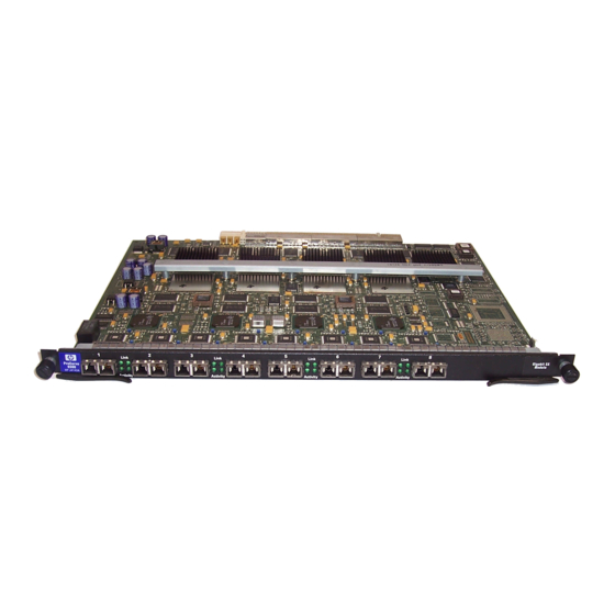
Installation Figure 2.4 Example of the front panel of an HP 9308M Routing Switch Figure 2.5 Example of the front panel of an HP 9304M Routing Switch Link Link Link Link Activity Activity Activity Activity Link Link Link Link Activity... -
Page 39: Attaching Apc Or Terminal
Installation and Getting Started Guide Insert the other end into a properly grounded electrical outlet. NOTE: The devices do not have power switches. They are powered on when the power cord is connected to the device and to a power source. If your installation requires a different power cord than that supplied with the device, be sure to obtain a power cord displaying the mark of the safety agency that defines the regulations for power cords in your country. - Page 40 Care Center (CCC). To contact the CCC for your area, see the support and warranty booklet ( Support is as Close as the World Wide Web! ) shipped with your HP product. CCCs are also listed in the HP ProCurve Networking Service and Support Guide available at http://www.hp.com/go/hpprocurve.
-
Page 41: Assigning A Permanentp
Most PC serial ports also require a cable with a female DB-9 connector. Terminal connections will vary, requiring either a DB-9 or DB-25 connector, male or female. Serial cable options between an HP Routing Switch and a PC terminal are shown in Figure 2.7. -
Page 42: How To Assign A Password
Installation switching and routing features. To access the CONFIG mode, you must already be logged into the Privileged level of the EXEC mode. By default, there are no CLI passwords. To secure CLI access, you must assign passwords. NOTE: You must use the CLI to assign a password. You cannot assign a password using the Web management interface or an SNMP network management application. -
Page 43: Assign A Permanent Ip Address
Terminal Using a Direct LAN Connection” on page 2-12.) On the HP 9304M, HP 9308M, or HP 9315M, you can configure up to 24 IP interfaces on each port, virtual interface, and loopback interface. See “Displaying and Modifying System Parameter Default Settings” on page 4- The following procedure shows how to add an IP address and mask to a Routing Switch port. -
Page 44: Mounting The Device
WARNING: The HP 9304M chassis exceeds 40 lbs. (18 kg), or 47.7 lbs.(21.6 kg) when fully populated with modules and power supplies. Also, the HP 9308M chassis exceeds 55 lbs. (24.9 kg) or 69.1 lbs. (31.3 kg) when fully populated with modules and power supplies. TWO OR MORE PEOPLE ARE REQUIRED WHEN LIFTING, HANDLING, OR MOUNTING THESE ROUTING SWITCHES. -
Page 45: Connecting Power To The Device
Proceed to “Connecting Power to the Device” on page 2-18. Figure 2.8 Installing an HP 9304M Routing Switch in a rack mount Connecting Power to the Device With physical installation of the Routing Switch complete, it is now time to power up the system and connect the network devices. -
Page 46: Connecting Network Devices
CAUTION: Before connecting Category 5 or better UTP copper networking cables to a chassis module on the HP 9304M or HP 9308M, use the CESD grounding tap (shipped with the HP 9304M, HP 9308M, or HP 9315M and with chassis modules designed for UTP copper networking cables). See the Cable Grounding Instructions included with the CESD grounding tap. - Page 47 Installation and Getting Started Guide • 1000BaseLX ports come equipped with SC connectors. • 1000BaseT ports come equipped with RJ-45 connectors. Figure 2.9 Pin assignment and signalling for 10/100BaseTX and 1000BaseT ports 100BaseTX and 1000BaseT 10BaseT Pin Assignment Pin Number MDI-X ports Pin Number MDI-X ports...
-
Page 48: Connecting To Others
Connecting to Other Switches, Routing Switches, and Ethernet Hubs For connections to Ethernet hubs, a 10/100BaseTX or 1000BaseT switch, or another HP Routing Switch, a crossover cable is required (Figure 2.10 or Figure 2.11). If the hub is equipped with an uplink port, it will require a straight-through cable instead of a crossover cable. -
Page 49: Connecting To Workstations
You also can perform trace routes. Pinging an IP Address To verify that an HP device can reach another device through the network, enter a command such as the following at any level of the CLI on the HP device: HP9300>... -
Page 50: Managing The Device
Logging on Through the CLI Once an IP address is assigned to an interface on the HP Routing Switch, you can access the CLI either through the direct serial connection to the device or through a local or remote Telnet session. - Page 51 Installation and Getting Started Guide appletalk boot some lines omitted for brevity... lock-address logging --More--, next page: Space, next line: Return key, quit: Control-c The software provides the following scrolling options: • Press the Space bar to display the next page (one screen at time). •...
-
Page 52: Searching And Filtering Output From Cli Commands
The following command filters the output of the show who command so it displays only lines that do not contain the word “closed”. This command can be used to display open connections to the HP device. HP9300# show who | exclude closed... - Page 53 --More--, next page: Space, next line: Return key, quit: Control-c At the --More-- prompt, you can press the forward slash key ( / ) and then enter a search string. The HP device displays output starting from the first line that contains the search string, similar to the begin option for show commands.
- Page 54 Installation --More--, next page: Space, next line: Return key, quit: Control-c -telnet The filtered results are displayed: filtering... sync-standby Synchronize active and standby module temperature temperature sensor commands terminal display syslog traceroute TraceRoute to IP node undebug Disable debugging functions (see also 'debug') undelete Undelete flash card files whois...
- Page 55 Installation and Getting Started Guide Table 2.4: Special Characters for Regular Expressions (Continued) Character Operation A dollar sign matches on the end of an input string. For example, the following regular expression matches output that ends with “deg”: deg$ An underscore matches on one or more of the following: •...
-
Page 56: Logging On Through The Web Management Interface
Logging On Through the Web Management Interface To use the Web management interface, open a web browser and enter the IP address of the HP device in the Location or Address field. The web browser contacts the HP device and displays a login dialog, as shown in Figure 2.12. - Page 57 Installation and Getting Started Guide The left pane of the Web management interface window contains a “tree view,” similar to the one found in Windows Explorer. Configuration options are grouped into folders in the tree view. These folders, when expanded, reveal additional options. To expand a folder, click on the plus sign to the left of the folder icon. You can configure the appearance of the Web management interface by using one of the following methods.
-
Page 58: Swapping Modules
Slots on the HP 9304M are numbered 1 – 4, from top to bottom. Slots on the HP 9308M are numbered 1 – 8, from left to right. - Page 59 Redundant Management Module (current product as of June 2002) (8-port) Management modules (MI) J4141A 16-port-copper-management- module (HP 9304M and HP 9308M only. ProCurve 9300 10/100 These modules will not work on Management Module (16-port) the HP 9315M) J4144A 8-port-gig-management-module HP ProCurve 9300 Gigabit SX...
- Page 60 J4140A 24-port-copper-module HP ProCurve 9300 10/100 (current product as of June 2002) Module (24-port) J4142A 24-port-100fx-module HP ProCurve 9300 100Base FX (current product as of June 2002) Module (24-port MT-RJ) J4143A 8-port-gig-module HP ProCurve 9300 Gigabit SX Module (8-port) J4145A...
- Page 61 Click the Add Module link to display the following panel. Select slot number from the Slot pulldown menu. • Slots on the HP 9304M are numbered 1 – 4, from top to bottom. • Slots on the HP 9308M are numbered 1 – 8, from left to right.
-
Page 62: Next Steps
Installation Next Steps Once the initial installation steps are completed, you can proceed with enabling routing protocols and configuring specific features on the Routing Switches as described in “Configuring Basic Features” on page 4-1. Configuration details for all routing protocols and advanced VLAN features can be found in the Advanced Configuration and Management Guide . - Page 63 Installation and Getting Started Guide 2 - 36...
-
Page 64: Using Redundantm
Using Redundant Management Modules This chapter describes the redundant management modules and how to configure and manage them. Redundant management modules provide increased routing capacity and failover for HP 9304M, HP 9308M, or HP 9315M Chassis devices. See the following sections for information: •... -
Page 65: Management Sessions
When a switchover occurs, the software sends a Syslog message to the local Syslog buffer and also to the SyslogD server, if you have configured the HP device to use one. In addition, if you have configured an SNMP trap receiver, the software sends an SNMP trap to the receiver. -
Page 66: Configuring The Redundant
If you are using redundant management modules, HP requires that you place both management modules in slots belonging to the same region. For example, if you place one management module in slot 5, HP recommends that you place the other management module in slot 6, 7, or 8. - Page 67 Installation and Getting Started Guide The <slot-num> parameter specifies the chassis slot to contain the module: • Slots in a 4-slot chassis are numbered 1 – 4, from top to bottom. • Slots in an 8-slot chassis are numbered 1 – 8, from left to right. •...
- Page 68 For example, if you place one management module in slot 5, HP requires that you place the other management module in slot 6, 7, or 8. This note does not apply to 4-slot or 8-slot Chassis devices.
- Page 69 Installation and Getting Started Guide • Slots in a 15-slot chassis are numbered 1 – 15, from left to right. This command overrides the default and makes the redundant management module in slot 5 the active module following the next reload. The change affects only the next reload and does not remain in effect for future reloads. To make the change permanent across future reloads, enter the write memory command to save the change to the startup-config file, as shown in the following example: HP9300(config)# redundancy...
-
Page 70: Determining Redundantm
Using Redundant Management Modules Inserting the Module You can remove and insert modules when the system is powered on. Make sure you adhere to the cautions noted in “Installation Precautions” on page 2-3. Put on an ESD wrist strap and attach the clip end to a metal surface (such as an equipment rack) to act as ground. - Page 71 Installation and Getting Started Guide • Slots in a 15-slot chassis are numbered 1 – 15, from left to right. USING THE CLI To display the status of a redundant management module using the CLI, enter the following command at any CLI level: HP9300>...
-
Page 72: Displaying Switchoverm
Using Redundant Management Modules The Status column shows the module status. The redundant management modules can have one of the following statuses: • ACTIVE – The module is currently the active management module. • STANDBY – The module is the standby management module. The statuses above apply only to management modules. -
Page 73: File Synchronizationb
Installation and Getting Started Guide USING THE CLI To view the system log, enter the following command at any level of the CLI: HP9300> show log Syslog logging: enabled (0 messages dropped, 0 flushes, 0 overruns) Buffer logging: level ACDMEINW, 8 messages logged level code: A=alert C=critical D=debugging M=emergency E=error I=informational N=notification W=warning Static Log Buffer:... - Page 74 Using Redundant Management Modules Figure 3.1 Redundant management module file synchronization Not automatically synchronized Automatically synchronized Automatically synchronized at startup or switchover at regular, user-configurable but can be configured to synchronize intervals at startup or switchover Startup-config also Also can be immediately synchronized automatically updated Also can be immediately using the CLI or Web management interface...
- Page 75 Installation and Getting Started Guide Sync boot image: FALSE Running-config sync interval is 10 seconds NOTE: The values shown in this example are the default values. Syntax: sync-standby NOTE: The sync-standby command has optional parameters. If you enter one of the parameters, the CLI synchronizes software between the modules.
- Page 76 Using Redundant Management Modules HP9300# sync-standby boot Syntax: sync-standby boot To immediately synchronize the flash code (system software) on the standby module with the boot code on the active module, enter the following command at the Privileged EXEC level of the CLI: HP9300# sync-standby code Syntax: sync-standby code To immediately synchronize the running-config on the standby module with the running-config on the active...
- Page 77 Installation and Getting Started Guide USING THE CLI The CLI commands for automating synchronization of software between the active and standby modules is the same as the syntax for immediately synchronizing the software. The only difference is the CLI level where you enter the commands.
-
Page 78: Switching Over To Thes
Using Redundant Management Modules NOTE: Do not click the Synchronize Boot Flash Now button unless you want the active module to immediately copy its boot flash image to the standby module. Click the Apply button to send the configuration change to the active module’s running-config file. If you want the change to remain in effect following the next system reload, select the Save link to save the configuration change to the active redundant management module's startup-config file. - Page 79 Installation and Getting Started Guide Select the Switch-over Active Module link. A message appears asking you to verify that you want to switch over from the active module to the standby. Select Yes to switch over or No to cancel the switchover request. •...
- Page 80 Mirror ports (for traffic diagnosis and troubleshooting) – see “Assigning a Mirror Port and Monitor Ports” on page 4-48 HP devices are configured at the factory with default parameters that allow you to begin using the basic features of the system immediately. However, many of the advanced features such as VLANs or routing protocols for the router must first be enabled at the system (global) level before they can be configured.
- Page 81 The Web management interface enables you to easily make numerous configuration changes by entering or changing information on configuration panels such as the one shown in Figure 4.1. Figure 4.1 System configuration panel for an HP Routing Switch You can perform the following configuration tasks from the System configuration panel: •...
-
Page 82: Configuring Basic System Parameters
Entering System Administration Information You can configure a system name, contact, and location for an HP Routing Switch and save the information locally in the configuration file for future reference. This information is not required for system operation but is suggested. -
Page 83: Configuring Simplen
Specifying an SNMP Trap Receiver You can specify a trap receiver to ensure that all SNMP traps sent by the HP device go to the same SNMP trap receiver or set of receivers, typically one or more host devices on the network. When you specify the host, you... - Page 84 The string is not used to authenticate access to the trap host but is instead a useful method for filtering traps on the host. For example, if you configure each of your HP devices that use the trap host to send a different community string, you can easily distinguish among the traps from different HP devices based on the community strings.
- Page 85 Specifying a Single Trap Source You can specify a single trap source to ensure that all SNMP traps sent by the HP device use the same source IP address. When you configure the SNMP source address, you specify the Ethernet port, loopback interface, or virtual interface that is the source for the traps.
- Page 86 You cannot configure the parameter using the Web management interface. Disabling SNMP Traps HP Routing Switches come with SNMP trap generation enabled by default for all traps. You can selectively disable one or more of the following traps. NOTE: By default, all SNMP traps are enabled at system startup.
- Page 87 Disabling Syslog Messages and Traps for CLI Access HP devices send Syslog messages and SNMP traps when a user logs into or out of the User EXEC or Privileged EXEC level of the CLI. The feature applies to users whose access is authenticated by an authentication-method list based on a local user account, RADIUS server, or TACACS/TACACS+ server.
-
Page 88: Configuring An Interface As The Cancelling An Outbound
If your Telnet server is configured to accept packets only from specific links or IP addresses, you can use this feature to simplify configuration of the Telnet server by configuring the HP device to always send the Telnet packets from the same link or source address. -
Page 89: Configuring An Interface As The Specifying A Simple Network
You can configure Routing Switches to consult SNTP servers for the current system time and date. NOTE: HP Routing Switches do not retain time and date information across power cycles. Unless you want to reconfigure the system time counter each time the system is reset, Hewlett-Packard recommends that you use the SNTP feature. - Page 90 Configuring Basic Features To display information about SNTP associations, enter the following command: HP9300# show sntp associations address ref clock when poll delay disp ~207.95.6.102 0.0.0.0 5.45 ~207.95.6.101 0.0.0.0 * synced, ~ configured Syntax: show sntp associations The following table describes the information displayed by the show sntp associations command. Table 4.1: Output from the show sntp associations command This Field...
-
Page 91: Setting The System Clock
Setting the System Clock In addition to SNTP support, HP switches and routers also allow you to set the system time counter. The time counter setting is not retained across power cycles and is not automatically synchronized with an SNTP server. - Page 92 HP9300# clock set 10:15:05 10-15-99 Syntax: [no] clock set <hh:mm:ss> <mm-dd-yy> | <mm-dd-yyyy> By default, HP switches and routers do not change the system time for daylight savings time. To enable daylight savings time, enter the following command: HP9300# clock summer-time...
-
Page 93: Changing The Default Gigabit Negotiation Mode
HP Chassis software provides a solution by changing the default negotiation behavior for Gigabit Ethernet ports. The new default behavior allows a port to establish a link with another port whether the other port is configured for auto-Gigabit or negotiation-off. - Page 94 Configuring Basic Features USING THE CLI To change the mode globally, enter a command such as the following: HP9300(config)# gig-default neg-off This command changes the global setting to negotiation-off. The global setting applies to all Gigabit Ethernet ports except those for which you set a different negotiation mode on the port level. To change the mode for individual ports, enter commands such as the following: HP9300(config)# int ethernet 4/1 to 4/4 HP9300(config-mif-4/1-4/4)# gig-default auto-gig...
-
Page 95: Limiting Broadcast , M
To limit the number of multicast packets an HP device can forward each second, use the following CLI method. USING THE CLI To globally limit the number of multicast packets an HP 9304M, HP 9308M, or HP 9315M Routing Switch forwards to 120,000 per second, enter the following command at the global CONFIG level of the CLI:... -
Page 96: Configuring Cli Banners
Setting a Message of the Day Banner You can configure the HP device to display a message on a user’s terminal when he or she establishes a Telnet CLI session. For example, to display the message “Welcome to HP ProCurve!” when a Telnet CLI session is... -
Page 97: Configuring Basic Port Parameters
• Green – indicates the link is good. This example shows the port states for an HP 9304M, HP 9308M, or HP 9315M Routing Switch that has not yet been connected to the rest of the network. 4 - 18... - Page 98 Configuring Basic Features Click on the Copy or Modify button next to a row of port information to display a configuration panel for that port. • Select Modify to change parameters for a port. • Select Copy to apply a port’s parameter settings to another port. Here is an example of the Port configuration panel.
-
Page 99: Assigning A Port Name
Installation and Getting Started Guide NOTE: A slot option appears on the chassis port configuration sheet. Slot corresponds to a module slot number. NOTE: The IEEE Tagging option appears only on the Port configuration sheet when tagging is enabled at the system level and a VLAN is defined on the system. -
Page 100: Modifying Port Mode
Configuring Basic Features The <value> can be one of the following: • 10-full • 10-half • 100-full • 100-half • auto The default is auto. USING THE WEB MANAGEMENT INTERFACE To modify port speed: Log on to the device using a valid user name and password for read-write access. The System configuration panel is displayed. -
Page 101: Disabling Or R E -Enabling A
The port can be made inactive (disable) or active (enable) by selecting the appropriate status option. The default value for a port is enabled. USING THE CLI To disable port 8 on module 1 of an HP Chassis device, enter the following: HP9300(config)# interface e 1/8 HP9300(config-if-1/8)# disable... - Page 102 Configuring Basic Features Disabling or Re-Enabling Flow Control You can configure full-duplex ports on a system to operate with or without flow control (802.3x). Flow control is enabled by default. USING THE CLI To disable flow control on full-duplex ports on a system, enter the following: HP9300(config)# no flow-control To turn the feature back on: HP9300(config)# flow-control...
- Page 103 Enabling or Disabling the Spanning Tree Protocol (STP) The STP (IEEE 802.1d bridge protocol) is supported on all HP Routing Switches. STP detects and eliminates logical loops in the network. STP also ensures that the least cost path is taken when multiple paths exist between ports or VLANs.
- Page 104 NOTE: The procedures in this chapter describe how to configure basic STP parameters. For more information about STP, see “Configuring Spanning Tree Protocol (STP)” on page 6-1. USING THE CLI To enable STP for all ports on an HP Routing Switch: HP9300(config)# spanning tree Syntax: [no] spanning-tree USING THE WEB MANAGEMENT INTERFACE Log on to the device using a valid user name and password for read-write access.
- Page 105 Installation and Getting Started Guide Table 4.3: Default STP Port Path Costs Port Type Default Path Cost 10 Mbps 100 Mbps Gigabit USING THE CLI EXAMPLE: Suppose you want to enable STP on a system in which no port-based VLANs are active and change the hello-time from the default value of 2 to 8 seconds.
-
Page 106: Enabling Or Disabling Layer 2 Switching
Enabling or Disabling Layer 2 Switching By default, HP Routing Switches support Layer 2 switching. These devices switch the routing protocols that are not supported on the devices. If IPX routing is not enabled, then IPX traffic also is switched. By default IPX routing is disabled. -
Page 107: Changing The Mac Age Time
Installation and Getting Started Guide USING THE CLI To globally disable Layer 2 switching on a Routing Switch, enter commands such as the following: HP9300(config)# route-only HP9300(config)# exit HP9300# write memory HP9300# reload To re-enable Layer 2 switching on a Routing Switch, enter the following: HP9300(config)# no route-only HP9300(config)# exit HP9300# write memory... -
Page 108: Configuring Static Mac Entries
Static MAC addresses can be assigned to HP Routing Switches. NOTE: HP Routing Switches also support the assignment of static IP Routes, static ARP, and static RARP entries. For details on configuring these types of static entries, see the “Configuring Static Routes” and “Creating Static ARP Entries”... - Page 109 Configuring Static ARP Entries HP recommends that you configure a static ARP entry to match the static MAC entry. In fact, the software automatically creates a static MAC entry when you create a static ARP entry.
- Page 110 Configuring Basic Features NOTE: When a static MAC entry has a corresponding static ARP entry, you cannot delete the static MAC entry unless you first delete the static ARP entry. To create a static ARP entry for a static MAC entry, enter a command such as the following: HP9300(config)# arp 1 192.53.4.2 aaaa.bbbb.cccc ethernet 1 The arp command allows you to specify only one port number.
-
Page 111: Defining Mac Address Filters
EtherType, LLC1 DSAP or SSAP numbers, and a SNAP EtherType. The filters apply to incoming traffic only. NOTE: MAC filters do not block management access to the HP device. For example, if you apply a filter to block a specific host, the filter blocks switch traffic from the host but does not prevent the host from establishing a management connection to the device through Telnet. - Page 112 Configuring Basic Features For Routing Switches, the MAC filter is applied only to those inbound packets that are to be switched. This includes those ports associated with a Virtual Ethernet (VE) interface. However, the filter is not applied to the VE; it is applied to the physical port.
- Page 113 Installation and Getting Started Guide NOTE: You must type in both bytes, otherwise the software will fill the field, left justified with a 00. Refer to RFC 1042 for a complete listing of SAP numbers. SNAP is defined as an IEEE 802.3 frame with the SSAP, DSAP, and control field set to AA, AA, and 03. Immediately following these is a five-byte SNAP header.
- Page 114 Configuring Basic Features Edit the value in the ID field if you want to assign the filter a different ID. The software automatically increments this field each time you add a MAC filter. Select the filter action by selecting Permit or Deny next to Action. Enter the source MAC address in the Source Address field.
- Page 115 Enabling Logging of Packets Denied by MAC Filters You can configure the HP device to generate Syslog entries and SNMP traps for packets that are denied by Layer 2 MAC filters. You can enable logging of denied packets on a global basis or an individual port basis.
- Page 116 Configuring Basic Features Syntax: [no] mac filter-group log-enable USING THE WEB MANAGEMENT INTERFACE You cannot configure a Layer 2 MAC filter to generate Syslog entries and SNMP traps for denied packets using the Web management interface. Defining Broadcast and Multicast Filters You can filter Layer 2 broadcast and multicast packets on specific ports.
- Page 117 Installation and Getting Started Guide Configuration Examples To configure a Layer 2 broadcast filter to filter all types of broadcasts, then apply the filter to ports 1/1, 1/2, and 1/3, enter the following commands: HP9300(config)# broadcast filter 1 any HP9300(config-bcast-filter-id-1)# exclude-ports ethernet 1/1 to 1/3 HP9300(config-bcast-filter-id-1)# write memory To configure two filters, one to filter IP UDP traffic on ports 1/1 –...
-
Page 118: Locking A Port To Restrict Addresses
Select the Save link at the bottom of the dialog. Select Yes when prompted to save the configuration change to the startup-config file on the device’s flash memory. Enabling or Disabling Routing Protocols HP Routing Switches support the following protocols: • AppleTalk •... -
Page 119: Displaying And Modifying System Parameter Default Settings
CLI. USING THE CLI To enable a protocol on an HP Routing Switch, enter router at the global CONFIG level, followed by the protocol to be enabled. The following example shows how to enable OSPF: HP9300(config)# router ospf... - Page 120 Configuring Basic Features • IP routes • IP route filters • IP sub-nets per port and per device • Static routes • IGMP • DVMRP routes • IPX/SAP entries • IPX/RIP entries • IPX/SAP filters • IPX/RIP filters • IPX forwarding filters •...
- Page 121 Installation and Getting Started Guide The tables you can configure as well the defaults and valid ranges for each table differ depending on the HP device you are configuring. NOTE: If you increase the number of sub-net addresses you can configure on each port to a higher amount, you might also need to increase the total number of sub-nets that you can configure on the device.
- Page 122 Configuring Basic Features HP9300# show default values sys log buffers:50 mac age time:300 sec telnet sessions:5 ip arp age:10 min bootp relay max hops:4 ip ttl:64 hops ip addr per intf:24 when multicast enabled : igmp group memb.:140 sec igmp query:60 sec when ospf enabled : ospf dead:40 sec ospf hello:10 sec...
-
Page 123: Using The Temperature Sensor
Installation and Getting Started Guide HP9300(config)# write memory HP9300(config)# exit HP9300# reload NOTE: If you accidentally enter a value that is not within the valid range of values, the CLI will display the valid range for you. To increase the number of IP sub-net interfaces you can configure on each port on a Routing Switch from 24 to 64, then increase the total number of IP interfaces you can configure on the device from 256 to 512, enter the following commands: HP9300(config)# system-max subnet-per-interface 64... -
Page 124: Displaying The Temperature
Configuring Basic Features to display the temperature and to change the warning and shutdown temperature levels. The software reads the temperature sensor according to the chassis poll time, which is 60 seconds by default. If the temperature equals or exceeds the shutdown temperature for five consecutive polls of the temperature by the software, the software shuts down the module to prevent damage. - Page 125 Installation and Getting Started Guide USING THE CLI To display the system log, enter the following command at any CLI level: HP9300# show log Syslog logging: enabled (0 messages dropped, 0 flushes, 0 overruns) Buffer logging: level ACDMEINW, 8 messages logged level code: A=alert C=critical D=debugging M=emergency E=error I=informational N=notification W=warning Static Log Buffer:...
- Page 126 Configuring Basic Features Edit the value in the Temperature Warning Threshold field to change the warning temperature. Edit the value in the Temperature Shutdown Threshold field to change the shutdown temperature. Click the Apply button to send the configuration change to the active module’s running-config file. If you want the change to remain in effect following the next system reload, select the Save link to save the configuration change to the startup-config file.
-
Page 127: Assigning A Mirror Port And Monitor Ports
Assigning a Mirror Port and Monitor Ports You can monitor traffic on HP ports by configuring another port to “mirror” the traffic on the ports you want to monitor. By attaching a protocol analyzer to the mirror port, you can observe the traffic on the monitored ports. -
Page 128: Configuring Port Mirroring And Monitoring
USING THE CLI Suppose you want to diagnose the in and out traffic on port 3 on a module in slot 4 of an HP 9304M, HP 9308M, or HP 9315M, and use port 1 in slot 4 as the mirror port. To do so, enter the following commands:... -
Page 129: Monitoring An Individual Trunk Port
USING THE WEB MANAGEMENT INTERFACE Suppose you want to diagnose the in and out on traffic on port 3 on a module in slot 4 of an HP 9304M, HP 9308M, or HP 9315M using port 1 in slot 4. To do so: Log on to the device using a valid user name and password for read-write access. - Page 130 Configuring Basic Features NOTE: If you do not use the config-primary-ind command in the example above, all the ports in the trunk group are monitored. Displaying the Current Mirror and Monitor Port Configuration You can display the current port mirroring and monitoring configuration using the following CLI method. USING THE CLI To display the current mirroring and monitoring configuration, enter the following command at any level of the CLI: HP9300(config)# show monitor...
- Page 131 Installation and Getting Started Guide 4 - 52...
-
Page 132: Configuring Trunk Groups
The Trunk Group feature allows you to manually configure multiple high-speed load-sharing links between two HP Routing Switches or between an HP Routing Switch and a server. You can configure from 2 – 8 ports as a trunk group, supporting transfer rates of up to 8 Gbps of bi-directional traffic. -
Page 133: Trunk Group Connectivity To A Server
Installation and Getting Started Guide Figure 5.1 Trunk Group application within an HP Routing Switch network HP Switch 4000 Power Users Trunk Group Dedicated 100 Mbps Server HP 9304M Router1 Gigabit Backbone HP 9304M Router2 Super Server NOTE: The ports in a trunk group make a single logical link. Therefore, all the ports in a trunk group must be connected to the same device at the other end. -
Page 134: Trunk Group Rules
– 20, 21 – 22, 23 – 24 NOTE: You can configure up to 12 trunk groups on an HP 9304M, HP 9308M, or HP 9315M 24-port 10/100 module. The 24-port 10/100 modules have the following primary ports: 1, 3, 5, 7, 9, 11, 13, 15, 17, 19, 21, and 23. - Page 135 Figure 5.3 shows an example of a valid 2-port trunk group link between devices. The trunk groups in this example are switch trunk groups, between two HP devices. Ports in a valid 2-port trunk group on one device are connected to two ports in a valid 2-port trunk group on another device.
- Page 136 Configuring Trunk Groups and Dynamic Link Aggregation Figure 5.4 shows examples of two Chassis devices connected by multi-slot trunk groups. Figure 5.4 Examples of multi-slot trunk groups 5 - 5...
- Page 137 Installation and Getting Started Guide Figure 5.5 shows the valid 2-port and 4-port trunk groups on chassis 10/100 modules. Figure 5.5 Valid 2-port and 4-port trunk groups on chassis 10/100 modules Valid 2-port trunk groups Valid 4-port trunk groups Additional Trunk Group Rules for Multi-Slot Trunk Groups •...
-
Page 138: Trunk Group Load Sharing
Switch. • Server trunk group – Use this type of trunk group to connect an HP Routing Switch to a file server or single host device. The HP device load shares across the ports in the trunk group. The method used for the load sharing depends on the following: •... -
Page 139: Configuring A Trunk Group
Installation and Getting Started Guide Table 5.1: HP Trunk Group Load Sharing (Continued) Traffic Layer Trunk Group Type Traffic Type Load-Sharing Basis Layer 3 Switch Destination IP address Destination IPX address AppleTalk Destination AppleTalk address All other traffic types Destination MAC... - Page 140 .Write startup-config done. Router2(config)# exit Router2# reload You then configure the trunk group on the HP ProCurve Switch 4000M. For more information, see the documentation for the HP ProCurve Switch 4000M. USING THE WEB MANAGEMENT INTERFACE To configure ports 5 – 8 as a trunk group between two Routing Switches or a Routing Switch and a server: Log on to the device using a valid user name and password for read-write access.
- Page 141 Example 2: Configuring a Trunk Group That Spans Multiple Gigabit Ethernet Modules in a Chassis Device To configure a trunk group that spans two modules in an HP 9304M, HP 9308M, or HP 9315M Chassis device, use one of the following methods.
- Page 142 Configuring Trunk Groups and Dynamic Link Aggregation Notice that the groups of ports meet the criteria for a multi-slot trunk group. Each group contains the same number of ports (two) and begins on a primary port (1/1 and 3/3). USING THE WEB MANAGEMENT INTERFACE Log on to the device using a valid user name and password for read-write access.
-
Page 143: Additional Trunking Options
Installation and Getting Started Guide NOTE: Hewlett-Packard recommends that you reload the software immediately after saving a trunk group configuration to flash memory, before making further configuration changes. Additional Trunking Options The CLI contains commands for doing the following: • Naming a trunk port •... -
Page 144: Displaying Trunk Group Configuration Information
Configuring Trunk Groups and Dynamic Link Aggregation To enable a port in a trunk group, enter a command such as the following at the trunk group configuration level: HP9300(config-trunk-4/1-4/4)# enable ethernet 4/2 Syntax: enable ethernet <portnum> Syntax: enable <portname> The syntax for disabling or re-enabling all ports in a trunk group at the same time is the same as in previous releases. - Page 145 Installation and Getting Started Guide USING THE CLI Enter the following command at any CLI level: HP9300(config)# show trunk Configured trunks: Trunk Type Ports Switch 1/1 1/2 1/3 1/4 2/1 2/2 2/3 2/4 Operational trunks: Trunk Type Ports Duplex Speed Tag Priority Switch 1/1 1/2 1/3 1/4 2/1 2/2 2/3 2/4 None None...
- Page 146 Configuring Trunk Groups and Dynamic Link Aggregation To display trunk group information for specific ports, enter a command such as the following: HP9300(config)# show trunk ethernet 1/1 to 1/8 Configured trunks: Trunk ID: 1 Type: Switch Ports_Configured: 8 Primary Port Monitored: Jointly Ports Port Names none...
- Page 147 Installation and Getting Started Guide Table 5.3: CLI Trunk Group Information (Continued) This Field... Displays... Duplex The mode of the port, which can be one of the following: • None – The link on the primary trunk port is down. •...
- Page 148 Configuring Trunk Groups and Dynamic Link Aggregation Table 5.4: Web Management Trunk Group Information (Continued) This Field... Displays... Port Members The ports in the trunk group. 5 - 17...
-
Page 149: Dynamic Link Aggregation
(aggregate link), without the need for manual configuration of the ports into trunk groups. When you enable link aggregation on a group of HP ports, the HP ports can negotiate with the ports at the remote ends of the links to establish trunk groups. - Page 150 HP devices. The HP rules apply to an HP device even if the device at the other end is from another vendor and uses different rules.
- Page 151 Passive mode – When you enable a port for passive link aggregation, the HP port can exchange LACPDU messages with the port at the remote end of the link, but the HP port cannot search for a link aggregation port or initiate negotiation of an aggregate link.
- Page 152 NOTE: If you are connecting the HP device to another vendor’s device and the link aggregation feature is not working, set the system priority on the HP device to a lower priority (a higher priority value). In some cases, this change allows the link aggregation feature to operate successfully between the two devices.
- Page 153 Installation and Getting Started Guide Figure 5.7 Ports with the same key in different aggregate links Port 1/1 Port 1/2 System ID: dddd.eeee.ffff Port 1/3 Ports 1/5 - 1/8: Key 4 All these ports have the same key, but are Port 1/4 in two separate aggregate links with...
- Page 154 1/3 and 1/4 in VLAN 2, change the key for ports 1/3 and 1/4. NOTE: If you change the key for a port group, HP recommends that you use the value 10000 or higher, to avoid potential conflicts with dynamically created keys.
- Page 155 You can enter one or more of the command’s parameters on the same command line, in any order. Displaying Link Aggregation Information To display the link aggregation configuration in effect on an HP device, use the following CLI method. USING THE CLI...
- Page 156 Configuring Trunk Groups and Dynamic Link Aggregation Table 5.5: CLI Display of Link Aggregation Information (Continued) This Field... Displays... Sys P Lists the system priority configured for this port. Port P Lists the port’s link aggregation priority. Lists the link aggregation key. Indicates the link aggregation mode, which can be one of the following: •...
- Page 157 Installation and Getting Started Guide Table 5.5: CLI Display of Link Aggregation Information (Continued) This Field... Displays... Indicates the distribution state of the port, which determines whether the port is ready to receive traffic over the trunk link. • Dis – The port is ready to receive traffic over the trunk link. •...
-
Page 158: Configuring Standard Stp Parameters
By default, each port-based VLAN on an HP device runs a separate spanning tree (a separate instance of STP). An HP device has one port-based VLAN (VLAN 1) by default that contains all the device’s ports. Thus, by default each HP device has one spanning tree. However, if you configure additional port-based VLANs on an HP device, then each of those VLANs on which STP is enabled and VLAN 1 all run separate spanning trees. -
Page 159: Stp Parameters And Defaults
Installation and Getting Started Guide STP Parameters and Defaults Table 6.1 lists the default STP states for HP devices. Table 6.1: Default STP States Default STP Type Default STP State Default STP State of New VLANs MSTP Disabled Disabled a.When you create a port-based VLAN, the new VLAN’s STP state is the same as the default STP state on the device. - Page 160 STP only within individual VLANs. USING THE CLI To enable STP for all ports in all VLANs on an HP device, enter the following command: HP9300(config)# spanning-tree This command enables a separate spanning tree in each VLAN, including the default VLAN.
-
Page 161: Changing Stp Bridge And Port Parameters
To change STP bridge parameters, use either of the following methods. USING THE CLI To change an HP device’s STP bridge priority to the highest value to make the device the root bridge, enter the following command: HP9300(config)# spanning-tree priority 0 The command in this example changes the priority on a device on which you have not configured port-based VLANs. - Page 162 The forward-delay <value> parameter specifies the forward delay and can be a value from 4 – 30 seconds. The default is 15 seconds. NOTE: You can configure an HP device for faster convergence (including a shorter forward delay) using Fast Span or Fast Uplink Span. See “Configuring Advanced Features” on page 6-19.
- Page 163 Installation and Getting Started Guide Modify the bridge STP parameters to the values desired. Click Apply to save the changes to the device’s running-config file. Select the Save link at the bottom of the dialog. Select Yes when prompted to save the configuration change to the startup-config file on the device’s flash memory.
-
Page 164: Displaying Stp Information
Configuring Spanning Tree Protocol (STP) Select the port (and slot if applicable) from the Port and Slot pulldown lists. Enter the desired changes to the priority and path cost fields. Click Apply STP Port to apply the changes to only the selected port or select Apply To All Ports to apply the changes to all the ports. - Page 165 Installation and Getting Started Guide USING THE CLI To display STP information, enter the following command at any level of the CLI: HP9300(config)# show span Global STP Parameters: VLAN Root Root Root Prio Max He- Ho- Fwd Last Bridge Cost Port rity Age llo ld dly Chang Address sec sec sec sec sec...
- Page 166 Configuring Spanning Tree Protocol (STP) Table 6.4: CLI Display of STP Information (Continued) This Field... Displays... Root Port The port on this device that connects to the root bridge. If this device is the root bridge, then the value is “Root” instead of a port number. Priority Hex This device or VLAN’s STP priority.
- Page 167 Installation and Getting Started Guide Table 6.4: CLI Display of STP Information (Continued) This Field... Displays... State The port’s STP state. The state can be one of the following: • BLOCKING – STP has blocked Layer 2 traffic on this port to prevent a loop.
- Page 168 Configuring Spanning Tree Protocol (STP) Table 6.5: Web Management Display of STP Information This Field... Displays... STP Bridge Parameters (global parameters) VLAN ID The port-based VLAN that contains this spanning tree (instance of STP). VLAN 1 is the default VLAN. If you have not configured port- based VLANs on this device, all STP information is for VLAN 1.
- Page 169 Installation and Getting Started Guide Table 6.5: Web Management Display of STP Information (Continued) This Field... Displays... State The port’s STP state. The state can be one of the following: • BLOCKING – STP has blocked Layer 2 traffic on this port to prevent a loop.
- Page 170 Configuring Spanning Tree Protocol (STP) USING THE CLI To display CPU utilization statistics for STP for the previous one-second, one-minute, five-minute, and fifteen- minute intervals, enter the following command at any level of the CLI: HP9300# show process cpu Process Name 5Sec(%) 1Min(%) 5Min(%)
- Page 171 Installation and Getting Started Guide USING THE WEB MANAGEMENT INTERFACE You cannot display this information using the Web management interface. Displaying the STP State of a Port-Based VLAN When you display information for a port-based VLAN, that information includes the STP state of the VLAN. Use either of the following methods to display port-based VLAN information.
- Page 172 Configuring Spanning Tree Protocol (STP) USING THE CLI To display the detailed STP information, enter the following command at any level of the CLI: HP9300# show span detail Spanning-tree of port-vlan 1 is disabled. ============================================== Multiple Spanning Tree (MSTP) Instance is Active on VLAN 22 ============================================== Global STP Timers: Bridge Hello TIMER is ACTIVE Global STP Timers: Bridge Hello TIMER value in sec 1...
- Page 173 Installation and Getting Started Guide This example shows the information displayed for standard STP (separate spanning tree in each port-based VLAN). The following example shows the information displayed when Single STP is enabled. HP9300(config)# show span detail ============================================== Global Single Spanning Tree (SSTP) is Active ============================================== Global STP Timers: Bridge Hello TIMER is ACTIVE Global STP Timers: Bridge Hello TIMER value in sec 1...
- Page 174 Configuring Spanning Tree Protocol (STP) The show span detail command shows the following information. Table 6.6: CLI Display of Detailed STP Information for Ports This Field... Displays... Port number and VLAN ID The port number and the VLAN the port belongs to. STP state The port’s STP state.
- Page 175 Installation and Getting Started Guide Table 6.6: CLI Display of Detailed STP Information for Ports (Continued) This Field... Displays... BPDU sent and received The number of BPDUs sent and received on this port since the software was reloaded. USING THE WEB MANAGEMENT INTERFACE The detailed display is not supported in the Web management interface.
-
Page 176: Fast Port Span
Configuring Spanning Tree Protocol (STP) You also can display the STP states of all ports by entering a command such as the following, which uses the brief parameter: HP9300(config)# show interface brief Port Link State Dupl Speed Trunk Tag Priori MAC Name Down None None None... - Page 177 Fast Port Span reduces the number of STP topology change notifications on the network. When an end station attached to a Fast Span port comes up or down, the HP device does not generate a topology change notification for the port. In this situation, the notification is unnecessary since a change in the state of the host does not affect the network’s topology.
-
Page 178: Fast Uplink Span
(two seconds for listening and two seconds for learning). The wiring closet switch must be an HP device but the device at the other end of the link... - Page 179 NOTE: When the wiring closet switch (HP device) first comes up or when STP is first enabled, the uplink ports still must go through the standard STP state transition without any acceleration. This behavior guards against temporary routing loops as the switch tries to determine the states for all the ports.
- Page 180 VLAN basis. Alternatively, you can configure an HP device to run a single spanning tree across all ports and VLANs on the device. The Single STP feature (SSTP) is especially useful for connecting an HP device to third-party devices that run a single spanning tree in accordance with the 802.1q specification.
- Page 181 VLAN and you want all the ports to be in the same STP broadcast domain. USING THE CLI To configure the HP device to run a single spanning tree, enter the following command at the global CONFIG level. HP9300(config)# spanning-tree single NOTE: If the device has only one port-based VLAN, the CLI command for enabling SSTP is not listed in the CLI.
- Page 182 Configuring Spanning Tree Protocol (STP) spanning tree. VLAN 4094 is used only by SSTP. A port can be a member of VLAN 4094 and another port-based VLAN at the same time without being tagged. All ports in VLAN 4094 share a common STP domain, but for all other traffic, the ports remain within the separate Layer 2 broadcast domains established by the port-based VLANs.
- Page 183 Installation and Getting Started Guide To display VLAN information, including the STP state of each VLAN, enter the following command at any CLI level: HP9300(config)# show vlans Total PORT-VLAN entries: 3 Maximum PORT-VLAN entries: 8 legend: [S=Slot] PORT-VLAN 1, Name DEFAULT-VLAN, Priority level0, in single spanning tree domain Untagged Ports: (S1) Untagged Ports: (S2) 9 10 11 12 13 14 15 16...
- Page 184 SuperSpan SuperSpan is an HP STP enhancement that allows Service Providers (SPs) to use STP in both SP networks and customer networks. The SP devices are HP devices and are configured to tunnel each customers' STP BPDUs through the SP.
- Page 185 SuperSpan uses a SuperSpan customer ID to uniquely identify and forward traffic for each customer. You assign the customer ID as part of the SuperSpan configuration of the HP devices in the SP. In Figure 6.1, the spanning trees of customer 1 and customer 2 do not interfere with one another because the SP network isolates each customer’s spanning tree based on the SuperSpan customer IDs in the traffic.
- Page 186 Layer 2 loop and block a port. The SP network remains unblocked. After the Preforwarding state, the HP ports change to the Forwarding state and forward data traffic as well as BPDUs. The default length of the Preforwarding state is five seconds. You can change the length of the Preforwarding state to a value from 3 –...
- Page 187 Installation and Getting Started Guide Customer and SP Use Multiple Spanning Trees Figure 6.3 shows an example of SuperSpan where both the customer network and the SP network use multiple spanning trees (a separate spanning tree in each port-based VLAN). Figure 6.3 Customer and SP using multiple spanning trees Customer...
- Page 188 Configuring Spanning Tree Protocol (STP) Figure 6.4 Customer using multiple spanning trees and SP using Single STP single span Customer Provider Region Region tagged to multiple vlan Root bridge for VLAN xx stp-boundary untagged to vlan 100 Customer traffic from different VLANs is maintained by different spanning trees, while the SP network is maintained by a single spanning tree.
- Page 189 Installation and Getting Started Guide Figure 6.5 Customer using Single STP and SP using multiple spanning trees single span customer Provider Region Region tagged to multiple vlan Root bridge for VLAN xx stp-boundary untagged to vlan 100 In this setup, the customer network is running a single spanning tree for VLANs 10 and 20. The traffic from VLAN 10 and 20 will be carried, or aggregated by VLAN 100 at the SP’s network.
- Page 190 To configure an HP device for SuperSpan: • Configure each interface on the HP device that is connected to customer equipment as a boundary interface. This step enables the interface to convert the destination MAC address in the customer's BPDUs.
-
Page 191: Stp Per Vlan Group
• Standard STP – You can configure only 128 instances of standard STP on an HP device. It is possible to need more instances of STP than this in large configurations. Using STP per VLAN group, you can aggregate STP instances. - Page 192 Configuring Spanning Tree Protocol (STP) • Optionally, configure master VLANs to contain the member VLANs. This is useful when you have a lot of member VLANs and you do not want to individually configure STP on each one. Each of the member VLANs in a master VLAN uses the STP settings of the master VLAN.
- Page 193 Installation and Getting Started Guide Configuration Example for STP Load Sharing Figure 6.8 shows another example of a STP per VLAN group implementation. Figure 6.8 More Complex STP per VLAN Group Example Member VLANs 2 - 200 Root bridge Root bridge Member VLANs for master VLAN 201 for master VLAN 1...
-
Page 194: Pvst/Pvst+ Compatibility
The information in this section is for reference. If you are running PVST/PVST+ on the Cisco devices and the default support for separate spanning trees in each VLAN on the HP devices, then no configuration is necessary for the devices to share spanning tree information. -
Page 195: Enabling Pvst/Pvst+ Statically
BPDUs to the other devices. The other devices forward the BPDUs as needed. The format of an STP BPDU differs depending on whether it is a Cisco PVST BPDU or an HP BPDU. HP and Cisco devices also can support single STP BPDUs, which use another format. -
Page 196: Displaying Pvst Information
Displaying PVST Information To display PVST information, use the following CLI method. USING THE CLI To display PVST information for ports on an HP device, enter the following command at any level of the CLI: HP9300(config)# show span pvst-mode VLAN... - Page 197 Installation and Getting Started Guide USING THE WEB MANAGEMENT INTERFACE You cannot display PVST information using the Web management interface. 6 - 40...
-
Page 198: Configuring Virtual Lans (Vlans)
NOTE: For information about the GARP VLAN Registration Protocol (GVRP), see “Configuring GARP VLAN Registration Protocol (GVRP)” on page 8-1. Overview This section describes the HP VLAN features. Configuration procedures and examples appear in later sections of this chapter. Types of VLANs You can configure the following types of VLANs on HP devices. - Page 199 Installation and Getting Started Guide When an HP device receives a packet on a port that is a member of a VLAN, the device forwards the packet based on the following VLAN hierarchy: • If the port belongs to an IP sub-net VLAN, IPX network VLAN, or AppleTalk cable VLAN and the packet belongs to the corresponding IP sub-net, IPX network, or AppleTalk cable range, the device forwards the packet to all the ports within that VLAN.
- Page 200 Configuring Virtual LANs (VLANs) Since each port-based VLAN is a separate Layer 2 broadcast domain, by default each VLAN runs a separate instance of the Spanning Tree Protocol (STP). Layer 2 traffic is bridged within a port-based VLAN and Layer 2 broadcasts are sent to all the ports within the VLAN.
-
Page 201: Default Vlan
Default VLAN By default, all the ports on an HP device are in a single port-based VLAN. This VLAN is called DEFAULT-VLAN and is VLAN number 1. HP devices do not contain any protocol VLANs or IP sub-net, IPX network, or AppleTalk cable VLANs by default. -
Page 202: Q Tagging
802.1q tagging is an IEEE standard that allows a networking device to add information to a Layer 2 packet in order to identify the VLAN membership of the packet. HP devices tag a packet by adding a four-byte tag to the packet. - Page 203 If you use tagging on multiple devices, each device must be configured for tagging and must use the same tag value. In addition, the implementation of tagging must be compatible on the devices. The tagging on all HP devices is compatible with other HP devices.
-
Page 204: Spanning Tree Protocol (Stp)
User-configured port-based VLAN Spanning Tree Protocol (STP) STP is disabled by default on HP Routing Switches. Also by default, each port-based VLAN has a separate instance of STP. Thus, when STP is globally enabled, each port-based VLAN on the device runs a separate spanning tree. -
Page 205: Virtual Interfaces
VLAN, then configure routing parameters on the virtual interfaces. For example, to enable an HP 9304M, HP 9308M, or HP 9315M Routing Switch to route IP traffic from one IP sub-net VLAN to another, you must configure a virtual interface on each IP sub-net VLAN, then configure the appropriate IP routing parameters on each of the virtual interfaces. - Page 206 Configuring Virtual LANs (VLANs) • Static ports You also can explicitly exclude ports. Dynamic Ports Dynamic ports are added to a VLAN when you create the VLAN. However, if a dynamically added port does not receive any traffic for the VLAN’s protocol within ten minutes, the port is removed from the VLAN. However, the port remains a candidate for port membership.
- Page 207 Installation and Getting Started Guide Ports in a new protocol VLAN that do not receive traffic for the VLAN’s protocol age out after 10 minutes and become candidate ports. Figure 7.8 shows what happens if a candidate port receives traffic for the VLAN’s protocol.
-
Page 208: Super Aggregated Vlans
VLAN, nor can you have an IPX protocol VLAN and an IPX network VLAN in the same port-based VLAN. As an HP device receives packets, the VLAN classification starts from the highest level VLAN first. Therefore, if an interface is configured as a member of both a port-based VLAN and an IP protocol VLAN, IP packets coming into the interface are classified as members of the IP protocol VLAN because that VLAN is higher in the VLAN hierarchy. -
Page 209: Routing Between Vlans
Some configurations may require simultaneous switching and routing of the same single protocol across different sets of ports on the same router. When IP, IPX, or Appletalk routing is enabled on an HP Routing Switch, you can route these protocols on specific interfaces while bridging them on other interfaces. In this scenario, you can create two separate backbones for the same protocol, one bridged and one routed. -
Page 210: Dynamic Port Assignment
Dynamic Port Assignment All Switch ports are dynamically assigned to any non-routable VLAN on HP Routing Switches. To maintain explicit control of the VLAN, you can explicitly exclude ports when configuring any non-routable Layer 3 VLAN on an HP Routing Switch. - Page 211 Installation and Getting Started Guide Figure 7.9 Port-based VLANs 222 and 333 9308M Port 1/1 Port 1/2 IP sub-net 1 IP sub-net 2 IPX network 1 IPX network 2 AppleTalk cable range 100 AppleTalk cable range 200 AppleTalk zone “Prepress” AppleTalk zone “CTP”...
- Page 212 Zone “B” Zone “A” Zone “B” Zone “A” To configure the Port-based VLANs on the HP 9308M Routing Switches in Figure 7.10, use the following method. USING THE CLI Configuring 9308M-A Enter the following commands to configure 9308M-A: HP9300> enable...
- Page 213 Installation and Getting Started Guide HP9308-A(config-vlan-4)# spanning-tree priority 500 HP9308-A(config-vlan-4)# vlan 5 name RED HP9308-A(config-vlan-5)# untag ethernet 1/13 to 1/16 ethernet 1/20 HP9308-A(config-vlan-5)# tag ethernet 1/25 to 1/26 HP9308-A(config-vlan-5)# spanning-tree HP9308-A(config-vlan-5)# spanning-tree priority 500 HP9308-A(config-vlan-5)# end HP9308-A# write memory Configuring 9308-B Enter the following commands to configure 9308-B: HP9300>...
-
Page 214: Modifying A Port-Based Vlan
Configuring Virtual LANs (VLANs) Syntax: [no] spanning-tree Syntax: spanning-tree [ethernet <portnum> path-cost <value> priority <value>] forward-delay <value> hello-time <value> maximum-age <time> priority <value> Modifying a Port-Based VLAN You can make the following modifications to a port-based VLAN: • Add or delete a VLAN port. •... - Page 215 Installation and Getting Started Guide HP9308-A(config-vlan-4)# Enter the following commands to exit the VLAN CONFIG mode and save the configuration to the system- config file on flash memory: HP9308-A(config-vlan-4)# HP9308-A(config-vlan-4)# end HP9308-A# write memory HP9308-A# NOTE: Beginning in software release 07.5.00, you can remove all the ports from a port-based VLAN without losing the rest of the VLAN’s configuration.
- Page 216 Configuring Virtual LANs (VLANs) NOTE: When port-based VLANs are not operating on the system, STP is set on a system-wide level at the global CONFIG level of the CLI. USING THE CLI Access the global CONFIG level of the CLI on 9308-A by entering the following commands: HP9308-A>...
-
Page 217: Configuring Ip Sub-Net, Ipx Network And Protocol-Based Vlans
IP sub-net 1 IP sub-net 2 IPX network 1 AppleTalk cable 100 AppleTalk cable 100 port 1/8 9304M Ports 1/4 - 1/6, 1/8 Ports 1/1 - 1/3, 1/8 Ports 1/1 - 1/6, 1/8 Ports 1/4 - 1/6, 1/8 AppleTalk IP sub-net 1... -
Page 218: Configuring An Ipv6 Protocol Vlan
Configuring Virtual LANs (VLANs) USING THE CLI To permanently assign ports 1/1 – 1/8 and port 1/25 to IP sub-net VLAN 1.1.1.0, enter the following commands: HP9304> en No password has been assigned yet... HP9304# config t HP9304(config)# HP9304(config)# ip-subnet 1.1.1.0/24 name Green HP9304(config-ip-subnet)# no dynamic HP9304(config-ip-subnet)# static ethernet 1/1 to 1/8 ethernet 1/25 To permanently assign ports 1/9 –... -
Page 219: Routing Between Vlans Using Virtual Interfaces
Routing Between VLANs Using Virtual Interfaces HP Routing Switches offer the ability to create a virtual interface within a Layer 2 STP port-based VLAN or within each Layer 3 protocol, IP sub-net, or IPX network VLAN. This combination of multiple Layer 2 and/or Layer 3 broadcast domains and virtual interfaces are the basis for Hewlett-Packard’s very powerful Integrated Switch... - Page 220 -IP sub-net 5 -OSPF area 0.0.0.0 -OSPF area 0.0.0.0 -IPX network 8 -IPX network 5 To configure the Layer 3 VLANs and virtual interfaces on the HP 9304M Routing Switch in Figure 7.12, use the following procedure. 7 - 23...
- Page 221 One way is to create a unique IP sub-net and IPX network VLAN, each with its own virtual interface and unique IP or IPX address within VLAN 2 on each HP 9304M. In this example, this is the configuration used for VLAN 3.
- Page 222 Now configure VLAN 4. Remember this is a flat segment that, in the previous example, obtained its IP default gateway and IPX router services from an external HP 9304M. In this example, HP9304-A will provide the routing services for VLAN 4. You also want to configure the STP priority for VLAN 4 to make HP9304-A the root bridge for this VLAN.
- Page 223 Installation and Getting Started Guide This completes the configuration for HP9304-A. The configuration for HP9304-B and C is very similar except for a few issues. • IP sub-nets and IPX networks configured on HP9304-B and HP9304-C must be unique across the entire network, except for the backbone port-based VLANs 5, 6, and 7 where the sub-net is the same but the IP address must change.
- Page 224 Configuring Virtual LANs (VLANs) HP9304-B(config-vlan-4)# untag ethernet 1/17 to 1/24 HP9304-B(config-vlan-4)# tag ethernet 1/25 to 1/26 HP9304-B(config-vlan-4)# spanning-tree HP9304-B(config-vlan-4)# vlan 5 name Rtr_BB_to_Bldg.1 HP9304-B(config-vlan-5)# tag e 1/25 HP9304-B(config-vlan-5)# no spanning-tree HP9304-B(config-vlan-5)# router-interface ve5 HP9304-B(config-vlan-5)# vlan 7 name Rtr_BB_to_Bldg.3 HP9304-B(config-vlan-7)# tag ethernet 1/26 HP9304-B(config-vlan-7)# no spanning-tree HP9304-B(config-vlan-7)# router-interface ve6 HP9304-B(config-vlan-7)# int ve5...
-
Page 225: Configuring Appletalk Cable Vlans
Installation and Getting Started Guide HP9304-C(config-vlan-ipx-network)# other-proto name block-other-protocols HP9304-C(config-vlan-other-proto)# exclude e 1/9 to 1/16 HP9304-C(config-vlan-other-proto)# no dynamic HP9304-C(config-vlan-other-proto)# interface ve 3 HP9304-C(config-vif-3)# ip addr 1.1.10.1/24 HP9304-C(config-vif-3)# ip ospf area 0.0.0.0 HP9304-C(config-vif-3)# int ve4 HP9304-C(config-vif-4)# ipx network 10 ethernet_802.3 HP9304-C(config-vif-4)# vlan 4 name Bridged_ALL_Protocols HP9304-C(config-vlan-4)# untag ethernet 1/17 to 1/24 HP9304-C(config-vlan-4)# tag ethernet 1/25 to 1/26 HP9304-C(config-vlan-4)# spanning-tree... -
Page 226: Configuration Example
Configuring Virtual LANs (VLANs) Configuration Example Figure 7.13 shows an example of an HP 9308M Routing Switch with four AppleTalk cable VLANs configured on a single port-based VLAN. In this example, port-based VLAN 10 is configured, then AppleTalk cable VLANs are configured on ports on chassis modules 2 and 3. - Page 227 Installation and Getting Started Guide HP9300(config-vlan-10)# appletalk-cable-vlan 1 name cable-one HP9300(config-vlan-10)# static ethe 2/1 to 2/2 ethe 3/1 to 3/2 HP9300(config-vlan-10)# router-interface ve 1 HP9300(config-vlan-10)# appletalk-cable-vlan 2 name cable-two HP9300(config-vlan-10)# static ethe 3/3 to 3/4 HP9300(config-vlan-10)# router-interface ve 2 HP9300(config-vlan-10)# appletalk-cable-vlan 3 name cable-three HP9300(config-vlan-10)# static ethe 3/5 to 3/6 HP9300(config-vlan-10)# router-interface ve 3 HP9300(config-vlan-10)# appletalk-cable-vlan 4 name cable-four...
-
Page 228: Configuring Protocol Vlans With Dynamic Ports
Configuring Virtual LANs (VLANs) Configuring Protocol VLANs With Dynamic Ports The configuration examples for protocol VLANs in the sections above show how to configure the VLANs using static ports. You also can configure the following types of protocol VLANs with dynamic ports: •... -
Page 229: Configuring An Ip Sub-Net Vlan With Dynamic Ports
Installation and Getting Started Guide Syntax: untagged ethernet <portnum> to <portnum> Syntax: untagged ethernet <portnum> ethernet <portnum> NOTE: Use the first untagged command for adding a range of ports. Use the second command for adding separate ports (not in a range). Syntax: ip-proto [name <string>] Syntax: ipx-proto [name <string>] Syntax: appletalk-cable-vlan <num>... -
Page 230: Configuring Uplink Ports Within A Port-Based Vlan
Configuring the Same IP Sub-Net Address on Multiple Port-Based VLANs For an HP device to route between port-based VLANs, you must add a virtual interface to each VLAN. Generally, you also configure a unique IP sub-net address on each virtual interface. For example, if you have three port-... - Page 231 Installation and Getting Started Guide interface. The IP address on each of the virtual interfaces must be in a separate sub-net. The HP device routes Layer 3 traffic between the sub-nets using the sub-net addresses. NOTE: Before using the method described in this section, see “Configuring VLAN Groups and Virtual Interface Groups”...
- Page 232 Protocol). The HP device performs proxy Address Resolution Protocol (ARP) for hosts that want to send IP traffic to hosts in other VLANs that are sharing the same IP sub-net address. If the source and destination hosts are in the same VLAN, the HP device does not need to use ARP.
- Page 233 ARP for the destination to the other VLANs that are using the same IP sub-net address. • If the destination is in the same VLAN as the source, the HP device does not need to perform a proxy ARP. To configure multiple VLANs to use the same IP sub-net address: •...
-
Page 234: Configuring Vlan Groups And Virtual Interface Groups
Configuring Virtual LANs (VLANs) Configuring VLAN Groups and Virtual Interface Groups To simplify configuration when you have many VLANs with the same configuration, you can configure VLAN groups and virtual interface groups. NOTE: VLAN groups and virtual interface groups are supported only on the chassis-based Routing Switches. When you create a VLAN group, the VLAN parameters you configure for the group apply to all the VLANs within the group. -
Page 235: Configuring A Virtual Interface Group
Installation and Getting Started Guide NOTE: The device’s memory must be configured to contain at least the number of VLANs you specify for the higher end of the range. For example, if you specify 2048 as the VLAN ID at the high end of the range, you first must increase the memory allocation for VLANs to 2048 or higher. -
Page 236: Displaying The Vlan Group And Virtual Interface Group Information
10.10.10.1/24. Allocating Memory for More VLANs or Virtual Interfaces HP 9304M, HP 9308M, or HP 9315M Routing Switches with Management II or higher modules support up to 4095 VLANs and 4095 virtual interfaces. The number of VLANs and virtual interfaces supported depends on the amount of DRAM memory on the management module. - Page 237 Virtual Interfaces Default Configurable Default Configurable Maximum Maximum Maximum Maximum HP 9304M, HP 9308M, or HP 9315M 4095 4095 Routing Switch with 256MB Redundant Management module (M4) HP 9304M, HP 9308M, or HP 9315M Routing Switch with 128MB Redundant Management...
-
Page 238: Configuring Super Aggregated Vlans
The network that connects them is transparent to the two devices. You can aggregate up to 4094 VLANs within another VLAN. This provides a total VLAN capacity on one HP device of 16,760,836 channels (4094 * 4094). - Page 239 Installation and Getting Started Guide Figure 7.16 Conceptual Model of the Super Aggregated VLAN Application ..Client 1 Client 5 Client 3 Client 1 192.168.1.69/24 Path = a single VLAN into which client VLANs are aggregated Channel = a client VLAN nested inside a Path sub-net...
-
Page 240: Configuring Aggregated Vlans
Configuring Virtual LANs (VLANs) Figure 7.17 Example Super Aggregated VLAN Application Client 6 Client 10 Client 8 Client 1 Client 3 Client 5 Port 1/1 Port 1/3 Port 1/5 Port 1/1 Port 1/3 Port 1/5 .. - Page 241 Installation and Getting Started Guide • Add the port connected to the core device (the device that will aggregate the VLANs) as a tagged port. This port must be tagged because all the client VLANs share the port as an uplink to the core device. •...
-
Page 242: Complete Cli Examples
Configuring Virtual LANs (VLANs) USING THE WEB MANAGEMENT INTERFACE You cannot enable VLAN aggregation using the Web management interface. The other options you need for configuring Aggregated VLANs are present in earlier software releases and are supported in the Web management interface. - Page 243 Installation and Getting Started Guide HP9300A(config-vlan-102)# exit HP9300A(config)# vlan 103 by port HP9300A(config-vlan-103)# tagged ethernet 2/1 HP9300A(config-vlan-103)# untagged ethernet 1/3 HP9300A(config-vlan-103)# exit HP9300A(config)# vlan 104 by port HP9300A(config-vlan-104)# tagged ethernet 2/1 HP9300A(config-vlan-104)# untagged ethernet 1/4 HP9300A(config-vlan-104)# exit HP9300A(config)# vlan 105 by port HP9300A(config-vlan-105)# tagged ethernet 2/1 HP9300A(config-vlan-105)# untagged ethernet 1/5 HP9300A(config-vlan-105)# exit...
- Page 244 Configuring Virtual LANs (VLANs) Commands for Device D Device D is at the other end of path and separates the channels back into individual VLANs. The tag type must be the same as tag type configured on the other core device (Device C). In addition, VLAN aggregation also must be enabled.
-
Page 245: Configuring Private Vlans
Installation and Getting Started Guide HP9300F(config-vlan-103)# exit HP9300F(config)# vlan 104 by port HP9300F(config-vlan-104)# tagged ethernet 2/1 HP9300F(config-vlan-104)# untagged ethernet 1/4 HP9300F(config-vlan-104)# exit HP9300F(config)# vlan 105 by port HP9300F(config-vlan-105)# tagged ethernet 2/1 HP9300F(config-vlan-105)# untagged ethernet 1/5 HP9300F(config-vlan-105)# exit HP9300F(config)# write memory Configuring Private VLANs A private VLAN is a VLAN that has the properties of standard Layer 2 port-based VLANs but also provides additional control over the packets that go in and out of the VLAN. -
Page 246: Implementation Notes
Configuring Virtual LANs (VLANs) By default, the private VLAN does not forward broadcast or unknown-unicast packets from outside sources into the private VLAN. If needed, you can override this behavior for broadcast packets, unknown-unicast packets, or both. (See “Enabling Broadcast or Unknown Unicast Traffic to the Private VLAN” on page 7-51.) You can configure a combination of the following types of private VLANs: •... - Page 247 Installation and Getting Started Guide Configuration Rules • You can use 10/100 and Gigabit Ethernet ports in a private VLAN. • You cannot configure any of the ports in a private VLAN to be members of a trunk group. • You cannot share a port between a private VLAN and a standard port-based VLAN or protocol VLAN.
-
Page 248: Enabling Broadcast Or Unknown Unicast Traffic To The Private Vlan
Configuring Virtual LANs (VLANs) active port in the primary VLAN and with each other. • isolated – specifies that the VLAN is a community private VLAN. The ports can communicate only with the active port in the primary VLAN. They cannot communicate with one another or with any other ports. •... -
Page 249: Cli Example For Figure 7.18
Installation and Getting Started Guide NOTE: You also can use MAC address filters to control the traffic forwarded into and out of the private VLAN. USING THE CLI To configure the ports in the primary VLAN to forward broadcast or unknown unicast traffic received from sources outside the private VLAN, enter the following commands at the global CONFIG level of the CLI: HP9300(config)# pvlan-preference broadcast flood HP9300(config)# pvlan-preference unknown-unicast flood... -
Page 250: Dual-Mode Vlan Ports
VLAN, flows from a Switch to this port. The dual-mode feature allows traffic for VLAN 20 and untagged traffic to go through the port at the same time. Figure 7.19 Dual-mode VLAN port example VLAN 20 Untagged Traffic Traffic HP Switch 4000 Port 2/11 Tagged, VLAN 20 dual-mode Port 2/9 Port 2/10 Tagged, VLAN 20 Untagged... -
Page 251: Configuring Vlans Using The Web Management Interface
Installation and Getting Started Guide The dual-mode feature is disabled by default. The dual-mode feature can be applied only to tagged ports. NOTE: This feature sometimes results in multiple MAC address entries for the same MAC address in the device’s MAC address table. In this case, each of the entries is associated with a different VLAN. One of the entries is in the configured VLAN while the other entry is in VLAN 0. -
Page 252: Configuring A Protocol-Based Vlan
Configuring Virtual LANs (VLANs) 11. Select the ports you are placing in the VLAN. To select a row, click on the checkbox next to the row number, then click on the Select Row button. NOTE: Ports highlighted in grey are members of a trunk group. The port right before the grey ports is the master port for that trunk group. -
Page 253: Configuring An Ip Sub-Net Vlan
Installation and Getting Started Guide Enter the VLAN ID that will contain the protocol VLAN in the VLAN ID field. Enter a name for the VLAN in the Protocol_VLAN_Name field. Select the virtual interface from the Router_Interface pulldown list if you configured a virtual interface for routing into and out of the VLAN. - Page 254 Configuring Virtual LANs (VLANs) • If at least one protocol VLAN is already configured and you are adding a new one, click on the IP Subnet link to display the IP Sub-net Protocol VLAN configuration panel. • If you are modifying an existing protocol VLAN, click on the Modify button to the right of the row describing the VLAN to display the configuration panel for the type of VLAN you are modifying.
-
Page 255: Configuring An Ipx Network Vlan
Installation and Getting Started Guide Configuring an IPX Network VLAN Log on to the device using a valid user name and password for read-write access. Click on the plus sign next to Configure in the tree view to expand the list of configuration options. Click on the plus sign next to VLAN in the tree view to expand the list of VLAN option links. -
Page 256: Configuring An Appletalk Cable Vlan
Configuring Virtual LANs (VLANs) NOTE: All the ports must be members of the port-based VLAN that contains this IPX network VLAN. See “Layer 3 Protocol-Based VLANs” on page 7-3. 11. Click the Add button (if you are adding a new VLAN) or the Modify button (if you are modifying an existing VLAN) to save the change to the device’s running-config file. -
Page 257: Displaying Vlan Information
Installation and Getting Started Guide Specify the port that are members for the VLAN: • Select Dynamic Port if you want the port membership to be dynamic. For information, see “Dynamic Ports” on page 7-9. • Click the Change Static Members button if you want to configure static ports. For information, see “Static Ports”... -
Page 258: Displaying Vlan Information For Specific Ports
Configuring Virtual LANs (VLANs) USING THE CLI Enter the following command at any CLI level. This example shows the display for the IP sub-net and IPX network VLANs configured in the examples in “Configuring an IP Sub-Net VLAN with Dynamic Ports” on page 7-32 and “Configuring an IPX Network VLAN with Dynamic Ports”... - Page 259 Installation and Getting Started Guide USING THE CLI To display VLAN information for all the VLANs of which port 7/1 is a member, enter the following command: HP9300(config)# show vlans e 7/1 Total PORT-VLAN entries: 3 Maximum PORT-VLAN entries: 8 legend: [S=Slot] PORT-VLAN 100, Name [None], Priority level0, Spanning tree Off Untagged Ports: (S7)
-
Page 260: Application Examples
An HP device enabled for GVRP can do the following: • Learn about VLANs from other HP devices and configure those VLANs on the ports that learn about the VLANs. The device listens for GVRP Protocol Data Units (PDUs) from other devices, and implements the VLAN configuration information in the PDUs. - Page 261 Installation and Getting Started Guide Figure 8.1 Example of GVRP Core Device Edge Device A Edge Device B Port 2/24 Port 2/1 Port 6/24 Port 1/24 Port 4/1 Port 4/24 Port 4/24 Port 4/1 Port 8/17 Port 4/1 Edge Device C Port 2/24 Port 4/24 In this example, a core device is attached to three edge devices.
-
Page 262: Dynamic Core And Dynamic Edge
Configuring GARP VLAN Registration Protocol (GVRP) Core Device Edge Device A Edge Device B Edge Device C GVRP is enabled on all GVRP is enabled on port GVRP is enabled on port GVRP is enabled on port ports. 4/24. Learning is 4/1. -
Page 263: Fixed Core And Dynamic Edge
GVRP is enabled. You cannot change the ID of the default VLAN after GVRP is enabled. • Single STP must be enabled on the device. HP’s implementation of GVRP requires Single STP. If you do not have any statically configured VLANs on the device, you can enable Single STP as follows:... -
Page 264: Configuring Gvrp
Configuring GARP VLAN Registration Protocol (GVRP) • All VLAN ports added by GVRP are tagged. • GVRP is supported only for tagged ports or for untagged ports that are members of the default VLAN. GVRP is not supported for ports that are untagged and are members of a VLAN other than the default VLAN. •... -
Page 265: Increasing The Maximum Configurable Value Of The Leaveall Timer
Installation and Getting Started Guide Increasing the Maximum Configurable Value of the Leaveall Timer By default, the highest value you can specify for the Leaveall timer is 300000 ms. You can increase the maximum configurable value of the Leaveall timer to 1000000 ms. NOTE: You must enter this command before enabling GVRP. -
Page 266: Disabling Vlan Learning
Configuring GARP VLAN Registration Protocol (GVRP) NOTE: Leaveall messages are still sent on the GVRP ports. Disabling VLAN Learning To disable VLAN learning on a port enabled for GVRP, enter a command such as the following at the GVRP configuration level: HP9300(config-gvrp)# block-learning ethernet 6/24 This command disables learning of VLAN information on port 6/24. -
Page 267: Converting Avlan Created By Gvrp Into A Statically -Configured Vlan
Installation and Getting Started Guide Timer Configuration Requirements • All timer values must be in multiples of 100 ms. • The Leave timer must be >= 3* the Join timer. • The Leaveall timer must be >= 5* the Leave timer. •... -
Page 268: Displaying Gvrp Information
Configuring GARP VLAN Registration Protocol (GVRP) NOTE: After you convert the VLAN, the VLAN name changes from “‘GVRP_VLAN_<vlan-id>“ to “STATIC_VLAN_<vlan-id>“. Displaying GVRP Information You can display the following GVRP information: • GVRP configuration information • GVRP VLAN information • GVRP statistics Displaying GVRP Configuration Information To display GVRP configuration information, enter a command such as the following: HP9300(config)# show gvrp... - Page 269 Installation and Getting Started Guide This display shows the following information. Table 8.1: CLI Display of Summary GVRP Information This Field... Displays... Protocol state The state of GVRP. The display shows one of the following: • GVRP is disabled on the system •...
- Page 270 Configuring GARP VLAN Registration Protocol (GVRP) To display detailed GVRP information for an individual port, enter a command such as the following: HP9300(config)# show gvrp ethernet 2/1 Port 2/1 - GVRP Enabled : YES GVRP Learning : ALLOWED GVRP Applicant : ALLOWED Port State : UP Forwarding...
-
Page 271: Displaying Gvrp Vlan Information
Installation and Getting Started Guide Table 8.2: CLI Display of Detailed GVRP Information for a Port (Continued) This Field... Displays... VLAN Membership The VLANs of which the port is a member. For each VLAN, the following information is shown: • VLAN ID –... - Page 272 Configuring GARP VLAN Registration Protocol (GVRP) This display shows the following information. Table 8.3: CLI Display of Summary VLAN Information for GVRP This Field... Displays... Number of VLANs in the GVRP The number of VLANs in the GVRP database. Database Note: This number includes the default VLAN (1), the GVRP base VLAN (4093), and the single STP VLAN (4094).
-
Page 273: Displaying Gvrp Statistics
Installation and Getting Started Guide Table 8.4: CLI Display of Summary VLAN Information for GVRP (Continued) This Field... Displays... DEFAULT Whether this is the default VLAN. BASE-VLAN Whether this is the base VLAN for GVRP. Timer to Delete Entry Running Whether all ports have left the VLAN and the timer to delete the VLAN itself is running. - Page 274 Configuring GARP VLAN Registration Protocol (GVRP) This display shows the following information for the port. Table 8.5: CLI Display of GVRP Statistics This Field... Displays... Leave All Received The number of Leaveall messages received. Join Empty Received The number of Join Empty messages received. Join In Received The number of Join In messages received.
-
Page 275: Displaying Gvrp Diagnostic Information
Installation and Getting Started Guide Displaying GVRP Diagnostic Information To display diagnostic information, enter the following command: HP9300# debug gvrp packets GVRP: Packets debugging is on GVRP: 0x2095ced4: 01 80 c2 00 00 21 00 e0 52 ab 87 40 00 3a 42 42 GVRP: 0x2095cee4: 03 00 01 01 02 00 04 05 00 02 04 05 00 07 04 05 GVRP: 0x2095cef4:... -
Page 276: Dynamic Core And Dynamic Edge
Configuring GARP VLAN Registration Protocol (GVRP) HP9300(config)# gvrp-enable HP9300(config-gvrp)# enable all These commands globally enable GVRP support and enable the protocol on all ports. Enter the following commands on edge device A: HP9300> enable HP9300# configure terminal HP9300(config)# vlan 20 HP9300(config-vlan-20)# untag ethernet 2/1 HP9300(config-vlan-20)# tag ethernet 4/24 HP9300(config-vlan-20)# vlan 40... -
Page 277: Fixed Core And Dynamic Edge
Installation and Getting Started Guide Fixed Core and Dynamic Edge In this configuration, GVRP learning is enabled on the edge devices. The VLANs on the core device are statically configured, and the core device is enabled to advertise its VLANs but not to learn VLANs. The edge devices learn the VLANs from the core. -
Page 278: Displaying Cdp Information
NOTE: When you enable interception of CDP packets, the HP device drops the packets. As a result, Cisco devices will no longer receive the packets. Enabling Interception of CDP Packets To enable the HP device to intercept and display CDP packets, enter the following command at the global CONFIG level of the CLI: HP9300(config)# cdp run Syntax: [no] cdp run The feature is disabled by default. -
Page 279: Displaying Neighbors
Command Line Interface Reference Displaying Neighbors To display the Cisco neighbors the HP device has learned from CDP packets, enter the following command: HP9300# show fdp neighbors Capability Codes: R - Router, T - Trans Bridge, B - Source Route Bridge... -
Page 280: Displaying Cdp Entries
Reading Cisco Discovery Protocol (CDP) Packets Displaying CDP Entries To display CDP entries for all neighbors, enter the following command: HP9300# show fdp entry * Device ID: Router Entry address(es): IP address: 207.95.6.143 Platform: cisco RSP4, Capabilities: Router Interface: Eth 1/1, Port ID (outgoing port): FastEthernet5/0/0 Holdtime : 124 seconds Version :... - Page 281 Command Line Interface Reference Syntax: clear fdp table To clear CDP statistics, enter the following command: HP9300# clear fdp counters Syntax: clear fdp counters 9 - 4...
-
Page 282: Determining The Softwarev
Chapter 10 Updating Software Images and Configuration Files This chapter describes how to copy and save configuration files and software image files. NOTE: If you are attempting to transfer a file using TFTP but have received an error message, see “Diagnostic Error Codes and Remedies for TFTP Transfers”... -
Page 283: Determining The Boot Image Version Running On The Device
The flash memory module contains only one boot image. Image File Types The following table lists the boot and flash image file types supported on each HP device. For information about a specific version of code, see the release notes. Management Module... -
Page 284: Upgrading The Boot Code
TFTP server. NOTE: HP devices are TFTP clients but not TFTP servers. You must perform the TFTP transaction from the HP device. You cannot “put” a file onto the HP device using the interface of your TFTP server. -
Page 285: Using Snmp To Upgrade Software
This command disables password checking for SNMP set requests. If a third-party SNMP management application does not add a password to the password field when it sends SNMP set requests to an HP device, by default the HP device rejects the request. -
Page 286: Rebooting
Changing the Block Size for TFTP File Transfers When you use TFTP to copy a file to or from an HP device, the device transfers the data in blocks of 8192 bytes by default. You can change the block size to one of the following if needed: •... - Page 287 Installation and Getting Started Guide USING THE WEB MANAGEMENT INTERFACE To initiate an immediate boot from the primary boot source: Click on the plus sign next to Command in the tree view to expand the list of command options. Select the Reload option. Select Yes when the Web management interface asks you whether you really want to reload.
-
Page 288: Loading And Saving Configuration Files
Updating Software Images and Configuration Files Loading and Saving Configuration Files For easy configuration management, all HP Routing Switches support both the download and upload of configuration files between the Routing Switch and a TFTP server on the network. You can upload either the startup configuration file or the running configuration file to the TFTP server for backup and use in booting the system. -
Page 289: Copying A Configuration File To Or From A Tftp Server
Logging Changes to the Startup-Config File You can configure an HP device to generate a Syslog message when the startup-config file is changed. The trap is enabled by default. The following Syslog message is generated when the startup-config file is changed:... -
Page 290: Dynamic Configuration Loading
You can load dynamic configuration commands (commands that do not require a reload to take effect) from a file on a TFTP server into an HP device’s running-config. You can make configuration changes off-line, then load the changes directly into the device’s running-config, without reloading the software. - Page 291 Installation and Getting Started Guide Preparing the Configuration File A configuration file that you create must follow the same syntax rules as the startup-config file the device creates. • The configuration file is a script containing CLI configuration commands. The CLI reacts to each command entered from the file in the same way the CLI reacts to the command if you enter it.
- Page 292 Maximum File Sizes for Startup-Config File and Running-Config Each HP device has a maximum allowable size for the running-config and the startup-config file. If you use TFTP to load additional information into a device’s running-config or startup-config file, it is possible to exceed the maximum allowable size.
-
Page 293: Using Snmp To Save And Load Configuration Information
Installation and Getting Started Guide To determine the size of an HP device’s running-config or startup-config file, copy it to a TFTP server, then use the directory services on the server to list the size of the copied file. To copy the running-config or startup-config file to a TFTP server, use one of the following commands. -
Page 294: Erasing Image And Configuration Files
You cannot delete image or configuration files using the Web management interface. Scheduling a System Reload In addition to reloading the system manually, you can configure the HP device to reload itself at a specific time or after a specific amount of time has passed. -
Page 295: Canceling A Scheduled Reload
You cannot cancel a scheduled reload using the Web management interface. Diagnostic Error Codes and Remedies for TFTP Transfers If an error occurs with a TFTP transfer to or from an HP Routing Switch, one of the following error codes is displayed. -
Page 296: Error
Updating Software Images and Configuration Files Error Message Explanation and action code TFTP session timeout. TFTP failed because of a time out. Check IP connectivity and make sure the TFTP server is running. TFTP out of buffer space. The file is larger than the amount of room on the device or TFTP server. - Page 297 Installation and Getting Started Guide 10 - 16...
-
Page 298: Appendix A Using Syslog
The device writes the messages to a local buffer that can hold up to 100 messages. You also can specify the IP address or host name of up to six SyslogD servers. When you specify a SyslogD server, the HP device writes the messages both to the system log and to the SyslogD server. -
Page 299: Displaying Syslog Messages
“Displaying the Syslog Configuration” on page A-3. Enabling Real-Time Display of Syslog Messages By default, to view Syslog messages generated by an HP device, you need to display the Syslog buffer or the log on a Syslog server used by the HP device. -
Page 300: Configuring The Syslog Service
The procedures in this section describe how to perform the following Syslog configuration tasks: • Specify a SyslogD server. You can configure the HP device to use up to six SyslogD servers. (Use of a SyslogD server is optional. The system can hold up to 100 Syslog messages in an internal buffer.) •... - Page 301 Installation and Getting Started Guide Table A.1: CLI Display of Syslog Buffer Configuration (Continued) This Field... Displays... messages dropped The number of Syslog messages dropped due to user-configured filters. By default, the software logs messages for all Syslog levels. You can disable individual Syslog levels, in which case the software filters out messages at those levels.
- Page 302 Using Syslog The static and dynamic buffers are both displayed when you display the log. HP9300(config)# show logging Syslog logging: enabled (0 messages dropped, 0 flushes, 0 overruns) Buffer logging: level ACDMEINW, 3 messages logged level code: A=alert C=critical D=debugging M=emergency E=error I=informational N=notification W=warning Static Log Buffer: Dec 15 19:04:14:A:Fan 1, fan on right connector, failed...
- Page 303 Installation and Getting Started Guide <num> d – day • • <num> h – hours <num> m – minutes • <num> s – seconds • For example, “188d1h01m00s” means the device had been running for 188 days, 11 hours, one minute, and zero seconds when the Syslog entry with this time stamp was generated.
-
Page 304: Displaying And Configuring Syslog Buffer Parameters Using The Web Management Interface
Using Syslog recent message, at the top of the list of messages, was generated when the device had been running for 21 days, seven hours, two minutes, and 40 seconds. HP9300(config)# show log Syslog logging: enabled (0 messages dropped, 0 flushes, 0 overruns) Buffer logging: level ACDMEINW, 38 messages logged level code: A=alert C=critical D=debugging M=emergency E=error I=informational N=notification W=warning... -
Page 305: Disabling Or Re-Enabling Syslog
Installation and Getting Started Guide NOTE: A change in the buffer size takes effect only after you restart the system. The buffer size does not affect how many entries the device can log on a SyslogD server. The number of entries the device can log on the server depends on the server’s configuration. -
Page 306: Disabling Logging Of A Message Level
Changing the Log Facility The SyslogD daemon on the SyslogD server uses a facility to determine where to log the messages from the HP device. The default facility for messages the HP device sends to the SyslogD server is “user”. You can change the facility using the following command. -
Page 307: Clearing The Syslog Messages From The Local Buffer
– reserved for local use Clearing the Syslog Messages from the Local Buffer To clear the Syslog messages stored in the HP device’s local buffer, enter the following command from the Privileged EXEC level the CLI: HP9300# clear logging... - Page 308 • Warnings • Notifications • Informational • Debugging Table A.2: HP Syslog Messages Message Level Message Explanation Alert Power supply <num>, <location>, failed A power supply has failed. The <num> is the power supply number. The <location> describes where the failed power supply is in the chassis.
- Page 309 Installation and Getting Started Guide Table A.2: HP Syslog Messages (Continued) Message Level Message Explanation Alert Fan <num>, <location>, failed A fan has failed. The <num> is the power supply number. The <location> describes where the failed power supply is in the chassis. The location can be one of the following: •...
- Page 310 Using Syslog Table A.2: HP Syslog Messages (Continued) Message Level Message Explanation Alert OSPF Memory Overflow OSPF has run out of memory. Alert OSPF LSA Overflow, LSA Type = Indicates an LSA database overflow. <lsa-type> The <lsa-type> parameter indicates the type of LSA that experienced the overflow condition.
- Page 311 The <ip-addr> is the duplicate IP address. The <mac-addr> is the MAC address of the device with the duplicate IP address. The <portnum> is the HP port that received the packet with the duplicate IP address. The address is the packet’s source IP address.
- Page 312 Using Syslog Table A.2: HP Syslog Messages (Continued) Message Level Message Explanation Warning list <acl-num> denied <ip-proto> Indicates that an Access Control List (ACL) <src-ip-addr> (<src-tcp/udp-port>) denied (dropped) packets. (Ethernet <portnum> <mac-addr>) -> The <acl-num> indicates the ACL number. <dst-ip-addr> (<dst-tcp/udp-port>), Numbers 1 –...
- Page 313 Indicates that the state of an OSPF interface rid <router-id>, intf addr <ip-addr>, has changed. state <ospf-state> The <router-id> is the router ID of the HP device. The <ip-addr> is the interface’s IP address. The <ospf-state> indicates the state to which...
- Page 314 Indicates that the state of an OSPF neighbor addr <ip-addr>, nbr rid <nbr-router-Id>, state has changed. <ospf-state> The <router-id> is the router ID of the HP device. The <ip-addr> is the IP address of the neighbor. The <nbr-router-id> is the router ID of the neighbor.
- Page 315 Indicates that the state of an OSPF virtual rid <router-id>, nbr addr <ip-addr>, neighbor has changed. nbr rid <nbr-router-id>, state <ospf-state> The <router-id> is the router ID of the HP device. The <ip-addr> is the IP address of the neighbor.
- Page 316 Indicates that an OSPF interface intf addr <ip-addr>, configuration error has occurred. pkt src addr <src-ip-addr>, The <router-id> is the router ID of the HP error type <error-type>, pkt type <pkt-type> device. The <ip-addr> is the IP address of the interface on the HP device.
- Page 317 Indicates that an OSPF virtual interface rid <router-id>, intf addr <ip-addr>, configuration error has occurred. pkt src addr <src-ip-addr>, The <router-id> is the router ID of the HP error type <error-type>, pkt type <pkt-type> device. The <ip-addr> is the IP address of the interface on the HP device.
- Page 318 Indicates that an OSPF interface intf addr <ip-addr>, authentication failure has occurred. pkt src addr <src-ip-addr>, The <router-id> is the router ID of the HP error type <error-type>, pkt type <pkt-type> device. The <ip-addr> is the IP address of the interface on the HP device.
- Page 319 Indicates that an OSPF virtual interface rid <router-id>, intf addr <ip-addr>, authentication failure has occurred. pkt src addr <src-ip-addr>, The <router-id> is the router ID of the HP error type <error-type>, pkt type <pkt-type> device. The <ip-addr> is the IP address of the interface on the HP device.
- Page 320 Indicates that an OSPF interface received a intf addr <ip-addr>, bad packet. pkt src addr <src-ip-addr>, The <router-id> is the router ID of the HP pkt type <pkt-type> device. The <ip-addr> is the IP address of the interface on the HP device.
- Page 321 Link State Advertisement pkt type is <pkt-type>, LSA type <lsa-type>, (LSA). LSA id <lsa-id>, LSA rid <lsa-router-id> The <router-id> is the router ID of the HP device. The <ip-addr> is the IP address of the interface on the HP device.
- Page 322 Link State Advertisement pkt type is <pkt-type>, LSA type <lsa-type>, (LSA). LSA id <lsa-id>, LSA rid <lsa-router-id> The <router-id> is the router ID of the HP device. The <ip-addr> is the IP address of the interface on the HP device.
- Page 323 Notification OSPF LSDB overflow, rid <router-id>, A Link State Database Overflow (LSDB) limit <num> condition has occurred. The <router-id> is the router ID of the HP device. The <num> is the number of LSAs. Notification OSPF LSDB approaching overflow, The software is close to an LSDB condition.
- Page 324 <type> Checksum message. Notification SRP intf state changed, intf <portnum>, addr A state change has occurred in an HP <ip-addr>, state <srp-state> Standby Router Protocol (SRP) interface. The <portnum> is the port. The <ip-addr> is the IP address of the SRP interface.
- Page 325 The number of ICMP packets exceeds the packets, stopping for <lockup> seconds!! <burst-max> threshold set by the ip icmp burst command. The HP device may be the victim of a Denial of Service (DoS) attack. All ICMP packets will be dropped for the number of seconds specified by the <lockup>...
- Page 326 Using Syslog Table A.2: HP Syslog Messages (Continued) Message Level Message Explanation Notification Transit TCP in interface <portnum> exceeds Threshold parameters for TCP transit <num> burst packets, stopping for <num> (through) traffic have been configured on an seconds!! interface, and the maximum burst size for TCP packets on the interface has been exceeded.
- Page 327 Bridge is new root, vlan <vlan-id>, A Spanning Tree Protocol (STP) topology root ID <root-id> change has occurred, resulting in the HP device becoming the root bridge. The <vlan-id> is the ID of the VLAN in which the STP topology change occurred.
- Page 328 Using Syslog A - 31...
- Page 329 Installation and Getting Started Guide A - 32...
-
Page 330: Hardware Specifications
100,000,000 packets per second. Chassis Modules Each slot of the HP 9315M, HP 9308M, and HP 9304M can be populated by either a switch module or a management module. All non-management modules (those without a serial management port), are referred to as switch modules. - Page 331 NOTE: The HP 9308M and HP 9304M allow only one MI management module. (MI management modules cannot be used in the HP 9315M.) Also, software release 7.1 or greater cannot be used in MI management modules due to the flash memory size limit.
- Page 332 Hardware Specifications Figure B.2 Example of an HP 9308M Routing Switch (8-slot) B - 3...
-
Page 333: System Architecture
Installation and Getting Started Guide Figure B.3 Example of an HP 9315M Routing Switch (15-slot) System Architecture Built on a fully non-blocking architecture, the chassis platform provides switching capacity in the core and on each interface module. Each interface module utilizes a high bandwidth, shared-memory switching fabric. This local switching fabric houses the forwarding engines and includes Application Specific Integrated Circuits (ASICs) that provide packet switching functions such as priority handling. -
Page 334: Slot And Port Numbers
Hardware Specifications Figure B.4 Example front panel of an HP 9304M Routing Switch 1000BaseSX or 1000BaseLX ports 10BaseT/100BaseTX ports Port LEDs Power LEDs Serial Port Link Link Link Link Activity Activity Activity Activity Reset Button Link Link Link Link Activity... -
Page 335: Leds
Installation and Getting Started Guide LEDs Each HP device is equipped with LEDs that denote port and power supply status. The tables below reflect the different port and expansion module port states. Table B.1: Chassis 100BaseFX, 1000BaseSX/LX, and 1000BaseT LEDS... -
Page 336: Temperature Sensor
Hardware Specifications 100BaseFX Ports The 100BaseFX ports are equipped with MT-RJ connectors and operate at 100 Mbps in full-duplex mode. 1000BaseSX Ports The 1000BaseSX ports operate in full-duplex mode and are equipped with SC connectors on fixed-configuration modules and can be mini-GBICs with LC connectors for mini-GBIC modules that support this port type. Multi- mode fiber cabling is supported. -
Page 337: Physical Dimensions
Installation and Getting Started Guide Physical Dimensions Table B.3: Physical dimensions for HP devices Platform Depth Width Length (Height) Weight 15-slot Chassis 15" 17.5" 29.75" 256 lbs. fully device populated 8-slot Chassis 15" 17.5" 23" 69.1 lbs. fully device populated 4-slot Chassis 15"... -
Page 338: Software Specifications
RFC support • Internet drafts support NOTE: For a list of features supported on a specific product, see the data sheet for that product. Standards Compliance HP devices support the following standards. • IEEE 802.3, 10BaseT • IEEE 802.3u, 100BaseTX, 100BaseFX •... -
Page 339: Rfc Support
Installation and Getting Started Guide RFC Support The following table lists the RFCs supported by HP devices. Table C.1: HP RFC Support RFC Number Protocol or Standard User Datagram Protocol (UDP) Trivial File Transfer Protocol (TFTP) Internet Protocol (IP) Internet Control Message Protocol (ICMP) - Page 340 Software Specifications Table C.1: HP RFC Support (Continued) RFC Number Protocol or Standard 1256 ICMP Router Discovery Protocol (IRDP) 1267 Border Gateway Protocol version 4 (BGP4) MIB 1340 Assigned numbers (where applicable) 1354 IP Forwarding Table MIB 1377 The PPP OSI Network Layer Control Protocol (OSINLCP)
-
Page 341: Internet Drafts
Installation and Getting Started Guide Table C.1: HP RFC Support (Continued) RFC Number Protocol or Standard 2362 IP Multicast PIM Sparse 2385 TCP MD5 Signature Option (for BGP4) 2439 BGP Route Flap Dampening 2453 BGP Route Information Protocol (RIP) version 2... - Page 342 7-10 100BaseFx B-7 limiting 4-16 802.1p Buffer QoS priority 7-5 Syslog A-9 A-10 802.3x Gigabit negotiation 4-23 9304M Routing Switch 2-10 2-11 9308M Routing Switch 2-11 Cable AppleTalk VLAN 7-28 length 2-20 AC power Straight-through 2-12 connector B-5 straight-through 2-22...
- Page 343 Installation and Getting Started Guide scroll control 2-23 Default VLAN 7-4 7-13 securing access 2-15 Desktop Installation 2-17 User EXEC level 2-14 Device location 4-3 Clock 4-12 Dimensions B-8 Command completion Duplex mode 4-21 CLI 2-23 Dynamic port 7-9 7-31 Community string aging 7-31 encryption 4-5...
- Page 344 Help LED Behavior 2-12 getting 1-3 LEDs B-6 Host name 4-3 redundant management module 3-7 Hot Swap 2-4 Lifting, warning 2-1 modules 2-5 Line editing commands 2-24 redundant power supply 2-8 Load sharing Humidity B-8 trunk group 5-7 Lock MAC address 4-39 Logging on IEEE tagging 4-31 CLI 2-23...
- Page 345 Installation and Getting Started Guide Netscape version required 2-31 types 7-8 Network Port-based VLAN connection 2-19 configuring 7-54 network connections default 7-4 7-13 troubleshooting 2-22 Power Network Mask 2-1 connector B-5 Power Cord 2-12 caution 2-3 2-19 Power supply Operating environment B-8 replacing 2-8 Operating temperature 2-3 Precautions...
- Page 346 Running-config file 10-7 Super User 2-15 Swapping modules 2-4 Switch age time 4-28 Scheduled reload 10-13 configuring basic Layer 2 parameters 4-24 Scroll control 2-23 disabling 4-27 Security Switchover assigning Enable password 2-15 redundant management module 3-1 MAC address lock 4-39 Syslog messages 3-9 Serial cable 2-12 Syslog A-3...
- Page 347 Installation and Getting Started Guide Virtual interface 7-4 7-12 7-22 VLAN 7-8 VLAN AppleTalk cable 7-1 7-28 broadcast leaks 7-10 configuring 7-1 default 7-4 7-13 displaying information 7-60 displaying port information 7-61 displaying summary information 7-60 dynamic port 7-9 7-31 aging 7-31 excluded port 7-10 IEEE tagging 4-31...
- Page 348 Technical information in this document is subject to change without notice. ©Copyright Hewlett-Packard Company 2000-2002. All rights reserved. Reproduction, adaptation, or translation without prior written permission is prohibited except as allowed under the copyright laws. Manual Part Number 5990-3041...
Need help?
Do you have a question about the 9304m and is the answer not in the manual?
Questions and answers