Sign In
Upload
Manuals
Brands
OMRON Manuals
Inverter
RX Series
OMRON RX Series Manuals
Manuals and User Guides for OMRON RX Series. We have
5
OMRON RX Series manuals available for free PDF download: User Manual, System Configuration Manual
Omron RX Series User Manual (688 pages)
High-function General-purpose Inverter
Brand:
Omron
| Category:
Inverter
| Size: 7.82 MB
Table of Contents
Introduction
3
Intended Readers
3
Notice
3
Manual Configuration
4
Manual Structure
5
Page Structure and Symbol Icons
5
Special Information
6
Sections in this Manual
7
Read and Understand this Manual
8
Safety Precautions
11
Indications and Meanings of Safety Information
11
Meanings of Signal Words
11
Explanation of Symbols
12
Precautions for Safe Use
14
Installation and Storage
14
Transportation, Installation, and Wiring
14
Operation and Adjustment
15
Maintenance and Inspection
15
Precautions for Correct Use
16
Restart Selection Function
16
Deceleration Stop Function
16
Operation Stop Command
16
Warning Label
17
Warning Description
17
Regulations and Standards
18
EC Directives and Ul/Cul Standards
18
Trademarks
19
Items to Check after Unpacking
20
Checking the Nameplate
20
Checking the Model
20
Checking the Accessories
21
Related Manuals
22
Revision History
23
Table of Contents
24
Overview
31
Section 1 Overview
32
Overview of Functions
32
Features of 3G3RX-V1 Series Inverter
32
Stall Prevention Function
33
Ease of Use
34
Compliance with Safety Standards
35
Classes of 3G3RX-V1 Series Inverter
36
Compliance with International Standards (EC Directives and Ul/Cul Standards)
37
Appearance and Part Names
38
Specifications
39
Standard Specifications
39
Common Specifications
41
External Dimensions
44
Restrictions
53
Comparison with Previous Model
54
Safety Information
59
Section 2 Design
60
Installation
60
Inverter Installation
60
Installation Environment
60
Installation Conditions
61
Ambient Temperature Control
61
Removal of each Part
65
Removing Covers
65
Removing Front Cover
66
Terminal Blocks
67
Preparing Backing Plate
69
Wiring
70
Standard Connection Diagram
70
Arrangement and Function of Main Circuit Terminal Block
71
Arrangement and Function of Control Circuit Terminal Block
72
Wiring for Main Circuit Terminals
76
Rs485 Communications Terminal Block
76
Before Wiring
91
Wiring for Control Circuit Terminals
99
Wiring for PG Board
105
Input Terminals
106
Wiring for RS485 Communications Terminals
109
Wiring Method
110
Wiring for Digital Operator
111
Wiring for Emergency Shutoff Function
112
Conformance to EC Directives
114
Emc Directive
114
Measures against Noise
115
Low-Voltage Directive
115
Reference Manuals for Options
116
Operation and Test Run
117
Precautions for Safe Use
118
Precautions for Correct Use
119
Operation of Digital Operator
120
Part Names and Descriptions
120
Key Operation Method
122
Data Display
123
Parameter Initialization
125
Overview of LCD Digital Operator
131
Connections and Functions of CX-Drive
132
CX-Drive Connection Method
132
Outline of CX-Drive
136
Flow of Test Run
140
Test Run Procedure
141
Parameter Setting
143
No-Load Run
144
Load Run
145
Parameter List
147
Section 4 Parameter List
148
Monitor Mode
148
Group D
148
Basic Function Mode
151
Group F: Basic Function Parameters
151
Extended Function Mode
152
Group A: Standard Function Parameters
153
Group B: Detailed Function Parameters
165
Group C: Multi-Function Terminal Function Parameters
174
Group H: Motor Control Parameters
185
Group P: Option Parameters
188
Group U: User Setting Display Parameters
195
Basic Settings
197
Section 5 Basic Settings
199
Parameter Display and Parameter Initialization
199
Display Selection
199
Parameter Initialization
202
V/F Control Settings
204
Control Method (V/F Characteristics)
204
Heavy Load/Light Load Selection
208
Motor Parameter Settings
214
Motor Capacity/Pole Number Selection
214
Electronic Thermal Function
214
Base Frequency and Maximum Frequency of Motor
218
RUN Command Settings
219
RUN Command Selection
219
Frequency Reference Settings
220
Frequency Reference Selection
220
Frequency Limit
229
Acceleration/Deceleration Time Settings
231
Acceleration/Deceleration Pattern
233
Automatic Optimum Acceleration/Deceleration
235
2-Step Acceleration/Deceleration Function
237
Stop Method Settings
239
Stop Selection
239
Free-Run Stop Selection
239
STOP Key Selection
242
Reset Method Settings
243
Reset
243
Restart after Resetting
244
Multi-Function Input Settings
247
Multi-Function Input Selection
247
Multi-Function Input Operation Selection
248
Input Terminal Response Time
248
Reverse Command (RV)
248
Multi-Step Speed Operation Function
249
Jogging (JG)
252
2-Step Acceleration/Deceleration (2CH)
253
Reset (RS)
253
3-Wire Input Function (STA, STP, F/R)
254
Multi-Function Output Settings
255
Multi-Function Output Selection
255
Multi-Function Output Operation Selection
256
Multi-Function Output ON/OFF Delay Time
256
Signal During RUN (RUN)
257
Constant Speed Arrival Signal (FA1)
257
Alarm Signal (AL)
258
0-Hz Detection Signal (ZS)
259
Operation Ready (IRDY)
259
Forward Run Signal (FWR)
260
Reverse Run Signal (RVR)
260
Torque Boost Function Settings
261
Torque Boost
261
Automatic Torque Boost
262
Manual Torque Boost
263
Measures against Overvoltage
264
Overvoltage Suppression Function During Deceleration
264
Regenerative Braking Function
266
Vector Control
269
Section 6 Vector Control
270
Overview of Vector Control
270
Hz Sensorless Vector Control
270
Position Control
271
Sensor Vector Control
271
Speed Control
271
Torque Control
271
Sensorless Vector Control
272
Sensorless Vector Control Parameter Settings
272
0-Hz Sensorless Vector Control Parameter Settings
272
Auto-Tuning of Motor Parameters
273
Motor Parameter Settings
279
Adjustment for Sensorless Vector Control
281
Adjustment for 0 Hz Sensorless Vector Control
282
Sensor Vector Control
283
Sensor Vector Control Parameter Settings
283
Overview of
284
PG Board Function Settings
285
Auto-Tuning of Motor Parameters
286
Operating Procedure
291
Motor Parameter Settings
292
Adjustment for Sensor Vector Control (Speed Control)
294
Speed Control
295
Speed Control Gain Parameters
295
P/PI Switching Function
296
Control Gain Switching Function
297
Torque Bias Function Settings
298
Torque Limit Function
299
Torque Limit Function Settings
299
Torque LADSTOP Function Settings
301
Pulse Train Position Control Mode
302
Pulse Train Position Control Mode Settings
302
Electronic Gear Function
304
Position Bias Function
306
Speed Bias Function
307
Absolute Position/High-Resolution Absolute Position Control Mode
308
Absolute Position/High-Resolution Absolute Position Control Mode Parameter Settings
308
Operation Sequences
311
Servo on Function
311
Origin Search Function
316
Teaching Function
318
Forward/Reverse Driving Stop and Position Limit Setting Functions
319
Position Limit Setting Function
320
Orientation Function
321
Orientation Function Parameter Settings
321
Torque Control
324
Torque Control Parameter Settings
324
Control Block Diagram
325
Detailed Functions
327
Section 7 Detailed Functions
328
Monitor Mode (Group D)
328
Basic Functions (Group F)
340
Run Direction Selection
342
Basic Functions (Group A)
343
Base Frequency
345
Maximum Frequency
345
Analog Input Filter
352
DC Injection Braking
364
Output Voltage Gain
364
DC Injection Braking Carrier Frequency
365
External DC Injection Braking
367
Frequency Jump Function
370
Pid Function
371
Feedforward Selection
374
Pid Deviation Reverse Output
375
Pid Variable Range Limit
375
Feedback Comparison Signal
376
Frequency Addition Function
386
Detailed Functions (Group B)
387
Restart Options
391
Free-Electronic Thermal Function
396
Electronic Thermal Warning Function
397
Overload Limit Function
398
Overload Warning Function
400
Soft Lock Function
401
Data Read/Write Selection
402
Reduced Voltage Startup Selection
403
Run Direction Limit Selection
403
Display Selection
404
User Parameter Automatic Setting Function
407
Reverse Rotation Prevention Function
409
Deceleration Stop on Power Interruption Function
414
Carrier Frequency
420
Starting Frequency
420
Clearing Fault Monitor Methods
422
Automatic Carrier Frequency Reduction Function
426
Cooling Fan Control
429
Brake Control Function
430
Initial Screen Automatic Return Function
433
Multi-Function Terminal Functions (Group C)
434
Mp Selection
466
Mp Gain Setting
467
Torque Monitor Function
469
Motor Parameters (Group H)
471
Option Functions (Group P)
473
User Setting Display Functions (Group U)
475
Communications Functions
477
Section 8 Communications Functions
478
Communication Specifications
478
Communications Test Mode
481
Modbus Method
482
Explanation of each Function Code
486
Exception Response
495
Saving a Change to Holding Register (Enter Command)
496
Modbus Communication Register Number List
498
Coil Number List
498
Monitor Function/Enter Command Register List
503
Group F Register List
513
Group A/B/C/H/P Register List
514
2Nd Control Register Number List
547
3Rd Control Register Number List
551
ASCII Method
553
Communications Procedure
553
Communications Commands
554
Command 0A
567
Command 0B
568
Positive and Negative Responses
568
Overview of Driveprogramming
571
Troubleshooting
575
Alarm Codes and Remedies
576
Alarm Display
576
Alarm Code List
577
Option Board Protective Function List
583
Warning Function
586
Other Indications on Digital Operator
588
Troubleshooting
589
Maintenance and Inspection
595
Precautions for Safe Use
596
Precautions for Correct Use
597
Inspection
598
Daily Inspection
598
Periodic Inspection
598
Inspection Items
599
Cleaning
602
Test Methods
603
Megger Test
603
Withstand Voltage Test
603
Inverter/Converter Unit Test
604
I/O Voltage/Current/Electric Power Measurement Method
606
Section 12 Options
611
Overview of Optional Equipment
611
Part Names and Descriptions
611
Regenerative Braking Unit (Model: 3G3AX-RBU)
613
Specifications
613
External Dimensions
615
Connection Examples
619
Braking Resistor (Model: 3G3AX-RBA/RBB/RBC)
620
Specifications
620
External Dimensions
621
Connection Example
623
Regenerative Braking Unit and Braking Resistor Combination Selection Table
624
DC Reactor (Model: 3G3AX-DL)
631
Specifications
631
External Dimensions
633
Connection Examples
636
AC Reactor (Model: 3G3AX-AL)
637
Specifications
637
External Dimensions
639
Connection Examples
640
Input Noise Filter (Model: 3G3AX-NFI)
641
Specifications
641
External Dimensions
643
Connection Examples
648
Output Noise Filter (Model: 3G3AX-NFO)
649
Specifications
649
External Dimensions
651
Connection Example
652
Radio Noise Filter (Model: 3G3AX-ZCL)
653
Specifications
653
External Dimensions
654
Connection Example
655
12-10EMC Noise Filter (Model: 3G3AX-EFI )
656
Specifications
656
External Dimensions
658
Connection Example
660
12-11Digital Operator (Model: 3G3AX-OP01/ OP05)
661
Specifications
661
Digital Operator (Model: 3G3AX-OP01/OP05)
661
External Dimensions
662
12-12Digital Operator Cable (Model: 3G3AX-OPCN )
664
Specifications
664
External Dimensions
664
12-13PG Board (Model: 3G3AX-PG01)
665
Specifications
665
PG Board (Model: 3G3AX-PG01)
665
External Dimensions
666
Connection Examples
666
12-14Ethercat Communications Unit (Model: 3G3AX-RX-ECT)
667
Specifications
667
Ethercat Communications Unit (Model: 3G3AX-RX-ECT)
667
External Dimensions
668
12-15Componet Communications Unit (Model: 3G3AX-RX-CRT-E)
669
Specifications
669
Componet Communications Unit (Model: 3G3AX-RX-CRT-E)
669
External Dimensions
670
12-16Devicenet Communications Unit (Model: 3G3AX-RX-DRT-E)
671
Specifications
671
Devicenet Communications Unit (Model: 3G3AX-RX-DRT-E)
671
External Dimensions
672
Appendices
673
Smoothing Capacitor Life Curve
674
Advertisement
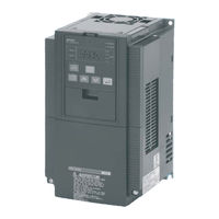
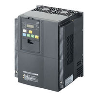
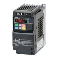
OMRON RX Series User Manual (414 pages)
200 V Class Three-Phase Input 0.4 to 55 kW; 400 V Class Three-Phase Input 0.4 to 132 kW
Brand:
OMRON
| Category:
Inverter
| Size: 4.88 MB
Table of Contents
Dimensions and Weights
6
Performance Data
6
Safety Precautions
7
Maintenance and Inspection
9
Operation and Adjustment
9
Precautions for Safe Use
9
Precautions for Correct Use
10
Checking before Unpacking
12
Checking the Product
12
Revision History
13
About this Manual
15
Table of Contents
17
Chapter 1 Overview
19
Appearance and Names of Parts
19
Functions
20
Appearance and Names of Parts
23
Chapter 2 Design
25
Installation
26
Safety Information
27
Wiring
31
Standard Connection Diagram
31
Main Circuit Terminals
32
Control Circuit Terminal
32
Chapter 3 Operation
52
Operation Method
52
Test Run Procedure
53
Test Run Operation
54
Part Names and Descriptions of the Digital Operator
57
Keys
60
Parameter Transition
61
Parameter List
67
Chapter 4 Functions
106
Monitor Mode
106
Function Mode
113
Base Frequency
116
Maximum Frequency
117
Binary Operation
122
Bit Operation
123
Torque Boost
124
Automatic Torque Boost
126
Constant Torque Characteristics (VC)
127
External DC Injection Braking
130
Frequency Limit
133
Automatic Energy-Saving Operation Function
141
Automatic Optimum Acceleration/Deceleration
141
Acceleration/Deceleration Pattern
143
Display Selection
158
Data Comparison Display
160
Basic Display
161
Starting Frequency
170
Carrier Frequency
170
Cooling Fan Control
177
External Trip
187
Commercial Switching
188
Wire Input Function
191
Analog Command Hold Function
196
Input Terminal Response Time
211
Sensorless Vector Control
219
Hz Sensorless Vector Control
220
Functions When PG Option Board (3G3AX-PG01) Is Used
224
Functions When PG Option Board (3G3AX- PG01) Is Used
224
Control Block Diagram
228
Electronic Gear Function
230
Orientation Function
234
Absolute Position Control Mode
236
Teaching Function
241
Pulse Train Frequency Input
243
Communication Function
244
Chapter 5 Maintenance Operations
317
Protective Functions and Troubleshooting
317
Warning Function
317
Protective Functions and Troubleshooting
318
Warning Function
326
Chapter 6 Inspection and Maintenance
329
Inspection and Maintenance
329
Product Disposal
330
Periodic Inspection
331
Chapter 7 Specifications
341
Standard Specification List
342
Common Specifications
344
Dimensional Drawing
347
Options
355
Omron RX Series User Manual (82 pages)
Brand:
Omron
| Category:
Inverter
| Size: 2.1 MB
Table of Contents
Table of Contents
2
1 Introduction
5
Handling of this Instruction Manual
5
Safety Instruction
5
Preparation and System Configuration
6
2 Specifications
7
3 Drive Programming Editor
8
Saving and Loading Programs
9
Editor
9
Toolbar
10
Common Commands
10
Commands for the Flowchart Editor
11
Commands for the Text Editor
11
Shortcut Keys
12
Designer Area
12
Toolbox Window
15
Block Parameters Window
16
Properties Window
17
Output Window
18
Creating a Program with Flowchart Editor
18
Creating a Program with Text Editor
19
Run a Program
19
Comments - Text Editor
19
Alias Definition - Text Editor
20
Region Definition - Text Editor
21
Conversion from Flowchart to Text
21
Conversion from Text to Flowchart
21
Find & Replace Function
22
4 Drive Program Structure
23
Tasks
23
Subroutines
24
5 Drive Programming User Variables
25
Initial Data
25
U(00) to U(31) or User Parameters
25
UL(00) to UL(07) or Internal User Parameters
25
Setting Variables
25
Set-Freq
25
Accel
25
Decel
26
Inverter Monitor Variables
26
Iout
26
Dir
26
Pib-Fb
26
F-Cnv
26
Tmon
27
Vout
27
Power
27
Run-Time
27
On-Time
27
Umon(0) to Umon(2)
27
Pos
28
Err-Cnt
28
Err(1)-Err(6)
28
DCV
28
Status
28
Terminal Variables
29
Xa(0)-Xa(2)
30
Ubw
31
Tdw
31
Ub(00)-Ub(07)
31
Digital Input Functions
32
Digital Output Functions
34
6 Drive Programming Instructions
36
Control Commands
36
Entry
36
End
36
Call
36
Sub
36
End Sub
36
Go to
38
On Trip
39
Ifs/ else / End if
41
Select / Case / End Select
42
For / Next
43
While / Wend
44
Until / Loop
45
Wait
46
Arithmetic and Logic Commands
47
(Substitution)
47
Addition
47
Subtraction
48
Multiplication
48
Division
49
Mod
49
Abs
50
And
51
Xor
53
Not
54
Inc
55
Dec
56
Input/Output Control Commands
57
Var = X(I)
57
Var = Xw
58
Y(I)=<Value
59
Yw = Value
60
Func = Value
61
Var = Func
62
Var = UB(I)
63
Var = Ubw
64
Ub(I) = Value
65
Ubw = Value
66
Timer Control Commands
67
Delay
67
Timer Set
68
Timer off
69
Parameter Control Commands
70
Chgparam
70
Monparam
71
Eepwrt
72
Rtcset
73
Inverter Control Commands
74
Run-FW
74
Run-RV
74
Stop
74
Set-Freq
74
Trip
76
Accel
77
Decel
77
7 Troubleshooting
78
8 Drive Programming Parameters - General Precautions
79
Parameters List Affected by Setting Order
79
Parameters List Affected by Rated Current(%)
79
Parameters List Affected by PID Enabled/Disabled
80
9 Insertion Points ( MX2 & RX )
81
Frequency' before ACC/DEC
81
Frequency' after ACC/DEC
81
Deviation' before PID Block
81
Advertisement
Omron RX Series User Manual (88 pages)
Inverter LCD Digital Operator
Brand:
Omron
| Category:
Inverter
| Size: 2.52 MB
Table of Contents
Intended Readers
3
Introduction
3
Manual Configuration
4
Manual Structure
5
Special Information
6
Sections in this Manual
7
Table of Contents
8
Contents
9
Read and Understand this Manual
10
Dimensions and Weights
12
Explanation of Symbols
13
Safety Precautions
13
Operation and Adjustment
15
Precautions for Safe Use
15
Maintenance and Inspection
16
Precautions for Correct Use
17
Regulations and Standards
18
Checking the Nameplate
19
Items to Check after Unpacking
19
Related Manuals
20
Revision History
21
Overview
23
Features
24
Supported Models
26
Specifications
27
External Dimensions
28
Recommended Cables
29
Part Names and Functions
31
Part Names
32
Operation Keys
33
Operation Keys
34
LCD Display
36
Installation and Wiring
39
Installation on the Inverter
40
Direct Installation on the Inverter
41
Direct Installation on the Inverter (RX, LX Models)
41
Installation on the Inverter Via Cable
42
Installation on the Inverter Via Cable (RX, LX, MX2 Models)
42
Checking the Operation after Installation
43
Date and Time Setting
44
Other Settings
44
Operation Procedures
46
Overview of Display Modes
46
Transition of Screens
46
Overview of each Mode
47
Function Mode
48
Changing the Display in each Mode
49
Operation in the Monitor Mode a
50
Operation in the Monitor Mode B
51
Operation in the Function Mode
52
Operation in the Trip Mode
53
Parameter Setting
55
Parameter Setting
56
Operation in the Option Mode
56
Details of each Option Mode Parameter
58
Related Inverter Parameters
60
Read/Write Functions
63
Single READ Function
64
Single WRITE Function
65
Quad READ Function
66
Quad VERIFY Function
68
Quad WRITE Function
70
Conditions for the Read/Write Operations
72
Error Messages and Troubleshooting
73
Error Messages and Remedies
74
Inverter Error Messages
74
LCD Digital Operator Error Messages
74
Troubleshooting
76
Troubleshooting
77
Maintenance
81
Battery Replacement Procedure
82
Battery Replacement
82
Index
85
OMRON RX Series System Configuration Manual (19 pages)
Brand:
OMRON
| Category:
Inverter
| Size: 1.89 MB
Table of Contents
System Configuration
1
Specifications
2
Type Designation
2
Common Specifications
3
Resistor Dimensions
9
Standard Connections
10
Terminal Block Specifications
10
Control Circuit
11
Inverter Heat Loss
12
Braking Unit
13
Ordering Information
14
Advertisement
Related Products
Omron RX Series Type V1
Omron RX-A2015
Omron RX-A2022
Omron RX-A2037
Omron RX-A2185
Omron RX-A2450
Omron RX-A4007
Omron RX-A4015
Omron RX-A4055
Omron RX-A4550
OMRON Categories
Blood Pressure Monitor
Controller
Accessories
Switch
Inverter
More OMRON Manuals
Login
Sign In
OR
Sign in with Facebook
Sign in with Google
Upload manual
Upload from disk
Upload from URL