Table of Contents
Advertisement
Quick Links
Advertisement
Table of Contents

Related Manuals for Interlogix TruVision 70


Summary of Contents for Interlogix TruVision 70
- Page 1 TruVision NVR 70 User Manual P/N 1073062-EN • REV A • ISS 15JUL15...
- Page 2 Copyright © 2015 United Technologies Corporation. Interlogix is part of UTC Building & Industrial Systems, a unit of United Technologies Corporation. All rights reserved. Trademarks and patents Trade names used in this document may be trademarks or registered trademarks of the manufacturers or vendors of the respective products.
-
Page 3: Table Of Contents
Content Important information 4 Chapter 1 Product introduction 5 Product overview 5 Default settings to access the device 5 Chapter 2 Physical installation 7 Installation environment 7 Unpacking the recorder and its accessories 7 Back panel description 8 HDD slots 9 Rack mounting 9 Chapter 3 Getting started 10... - Page 4 Search bookmarked recordings 38 Search snapshots 38 Search event logs 38 Chapter 8 Archiving files 42 Overview of archiving 42 Manually archive files 42 Automatically archive files 43 Archive video clips 43 Export video recordings via TruVision Navigator 43 Using TruVision Player 44 Watermarking 45 Chapter 9 Web browser configuration 46...
- Page 5 Chapter 13 Alarm and event setup 78 Set up alarm inputs 78 Set up alarm outputs 79 Manual trigger 80 Buzzer settings 80 Alarm notification 81 Detect video loss 82 Alarm host setup 83 Chapter 14 Device management 84 Time and date settings 84 General recorder settings 85 Configuration files 87 Upgrade system firmware 88...
-
Page 6: Important Information
Important information Advisory messages Advisory messages alert you to conditions or practices that can cause unwanted results. The advisory messages used in this document are shown and described below. WARNING: Warning messages advise you of hazards that could result in injury or loss of life. They tell you which actions to take or to avoid in order to prevent the injury or loss of life. -
Page 7: Product Introduction
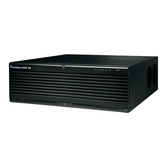
Chapter 1 Product introduction Product overview This recorder is a high performance network video recorder that can store, search, export and manage video from up to 400 Mbps of incoming camera bandwidth, or up to 128 IP cameras. There are many redundancy features to ensure system stability failure such as RAID, hot spare mode, network redundancy, and redundant power supplies. - Page 8 Table 1: Default user names and passwords User Description Administrator There can only be one administrator. The user name is “admin”. The name cannot be modified. The default password is 1234. Operator The default user name is “operator”. The default password is 2222. Guest The default user name is “guest”.
-
Page 9: Physical Installation
Chapter 2 Physical installation This section describes how to install the recorder. Installation environment When installing your product, consider these factors: • Ventilation • Temperature • Humidity • Chassis load Ventilation: Do not block any ventilation openings. Install in accordance with the manufacturer’s instructions. -
Page 10: Back Panel Description
1BChapter 2: Physical installation • AC power cords • Recorder • Hard drive kits • CD with software and manuals • TruVision NVR 70 Quick Start Guide • TruVision NVR 70 User Manual (on CD) • TruVision Recorder Operator Guide (on CD) Back panel description The figure below shows the back panel connections and describes each connector on a typical TVN 70 network video recorder. -
Page 11: Hdd Slots
1BChapter 2: Physical installation Description Specification eSATA Connect an optional eSATA drive to extend the internal storage. 16 alarm inputs Connect physical alarms such as detectors, push buttons, etc. Redundancy power Connect two PSUs. The PSUs are shipped with the supplies (X2) recorder. -
Page 12: Chapter 3 Getting Started
Chapter 3 Getting started Power on the recorder Before starting the recorder, connect at least one monitor. Otherwise, you will not be able to see the user interface and operate the device. The recorder comes equipped with a universal power supply that will auto-sense 110/240 V, 60/50 Hz. - Page 13 2BChapter 3: Getting started Important: Your TruVision device is delivered with default user name and password credentials for initial access, easy configuration and auto discovery. For security reasons, it is highly recommended to change the default credentials. To use the Startup wizard: 1.
- Page 14 2BChapter 3: Getting started 5. Time and date configuration: Select the desired system time and time zone. If Daylight saving time (DST) is required, check Enable DST and enter the desired summer and winter times. Note: The system time and date are visible on screen. However, the time and date shown on-screen are set in the camera settings.
- Page 15 2BChapter 3: Getting started To search for available cameras, click Search/Add. All the cameras found will be listed on screen. Select the desired cameras and click to add to your list. If you already know the specific camera to add, enter its IP address, protocol, user name, transfer protocol, registration mode, management port and password, and click OK.
- Page 16 2BChapter 3: Getting started 9. When all the required changes have been entered, a summary page appears showing all the settings. Click Finalize to exit the Wizard. The recorder is now ready to use. For a description of the recorder interface, see “Web browser interface” on page 17. TruVision NVR 70 User Manual...
-
Page 17: Operating Instructions
Chapter 4 Operating instructions Control the recorder You operate the recorder through a browser interface, which provides full functionality for viewing, playback and recorder configuration. You can also use TruVision Navigator or TVRmobile. Please refer to the TruVision Navigator and TVRmobile user manuals for more information. -
Page 18: Access The Web Browser
3BChapter 4: Operating instructions Figure 2: TVN 70 front panel The controls on the front panel include: Table 2: Front Panel Elements Name Description Front panel lock You can lock or unlock the front panel with a key. It provides access to the HDDs. -
Page 19: Web Browser Interface
3BChapter 4: Operating instructions Default user values: User ID: admin User ID: operator User ID: guest Password: 1234 Password: 2222 Password: 3333 The default values for recorder network settings are: • IP address - 192.168.1.82 • Subnet mask - 255.255.255.0 •... - Page 20 3BChapter 4: Operating instructions Figure 3: Browser window 1. Menu toolbar: Setup options available for the selected menu function. Move the mouse over a menu function and click to select it. There are four menu modes: Live View, Playback, Log Search, and Configuration.
-
Page 21: Live View
Chapter 5 Live view Live view mode is the normal operating mode of the unit where you watch live images from the cameras. The recorder automatically enters into live view mode once powered up. Web browser live view The recorder web browser lets you view, record, and play back videos as well as manage all aspects of the recorder from any PC with Internet access. - Page 22 4BChapter 5: Live view Name Description Camera live view and Select the camera for live viewing and recording. recording Click the button to start/stop live view from the selected camera. Click the button to start/stop local recording on your PC from the selected camera.
-
Page 23: Custom Views
4BChapter 5: Live view Custom views You can easily group cameras so that they appear in live view together. This allows you, for example, to quickly see all the cameras in a pre-defined part of the building such as a parking lot or different floors. -
Page 24: Digital Zoom
4BChapter 5: Live view 4. To change a camera’s streaming type, click the desired camera. The camera button changes to show the streaming type. 5. To add a camera to a custom view list, select the desired camera from the list of cameras not included in the custom view and click the button in front the camera name. -
Page 25: Preset Tours
4BChapter 5: Live view Figure 5: PTZ controls panel 1. Directional pan/auto-scan buttons: Controls the movements and directions of the PTZ. Center button is used to start auto-pan by the PTZ dome camera. 2. Adjust speed of PTZ dome camera. 3. - Page 26 4BChapter 5: Live view Figure 6: Preset tour interface Run preset tour Stop preset tour Save preset tour Delete preset Add preset tour Edit preset step To call up a preset tour: 1. In live view, click the PTZ/Video parameters button to open the PTZ controls panel. Select the desired camera from the camera list.
- Page 27 4BChapter 5: Live view Figure 7: Shadow tour interface Save shadow tour Stop shadow tour Record shadow tour Run shadow tour To call up a shadow tour: 1. In live view, click the PTZ/Video parameters button to open the PTZ controls panel. Select the desired camera from the camera list.
-
Page 28: Playback Functionality
Chapter 6 Playback functionality The recorder lets you quickly locate and play back recorded video. There are three ways to play back video: Web browser TruVision Navigator TVRmobile You can search video by specific time, events, motion detection, bookmarks, or snapshots (see Chapter 7 “Searching files”... -
Page 29: The Playback Control Toolbar
5BChapter 6: Playback functionality Figure 8: Playback window (12-hour playback shown) 1. Camera panel. Select the cameras for 7. Streaming. Select the streaming type: Main playback. Move the mouse over the area to stream or substream. display the list of cameras available. 8. - Page 30 5BChapter 6: Playback functionality Figure 9: Playback control toolbar Description Recording progress bar: This bar displays how much of the period has been recorded. It indicates in color the type of recording. Display playback on single screen or multiscreens. Also display the video tiles in full-screen mode. Playback control toolbar: Synchronize playback: Use to synchronize the playback time of several cameras when in multiscreen format.
-
Page 31: Display Order Of Cameras On Screen
5BChapter 6: Playback functionality Display order of cameras on screen By default, playback is in full-screen mode. You can easily change the display mode to multiscreen using the single/multiscreen buttons at the bottom of the screen. You can play back up to 16 cameras at a time. -
Page 32: Synchronize Play Back Across Cameras
5BChapter 6: Playback functionality 3. To playback the camera in for selected video tile, click the Play button. You can click the Play button for each individual video tile to start playback. Play back starts immediately in the video tile. Playback starts for each tile at the time displayed on the time line. -
Page 33: Digital Zoom In Playback
5BChapter 6: Playback functionality To play back frame-by-frame: 1. In playback mode, click the Single Frame button in the playback control toolbar. The speed changes to single frame. 2. Click the Restore button return to normal speed. Digital zoom in playback You can zoom in on an image during playback to see it in greater detail. - Page 34 5BChapter 6: Playback functionality To create a bookmark: 1. In the playback mode, click the time line bar where you want the bookmark to start or enter in the exact time of the desired playback start point in the jump start box. The yellow time line jumps to this position.
-
Page 35: Chapter 7 Searching Files
Chapter 7 Searching files This chapter describes how to search and playback recorded videos as well as search them by time, events, bookmarks, and snapshots. It also describes searching for event logs. Advanced search video menu You can easily search and play back recorded videos by time and date and events. A search will usually produce a list of files, which may extend to several pages. -
Page 36: Search For Motion Events In Playback
6BChapter 7: Searching files Description The Advanced Search window has two submenus that allow you to carry out different searches by theme: Time and date: Search all video by time and date of recording. Event: Search only event recorded files. Files can be searched by event type: Alarm input, motion detection, text insertion, or VCA alarms. -
Page 37: Search And Play Back Recordings By Time And Video Type
6BChapter 7: Searching files 4. Click Search. Motion events are highlighted as blue lines on the recording progress bar. If required, click Zoom In button to zoom in on the bar to better distinguish the time periods of the motion events. -
Page 38: Search And Play Back Recordings By Event
6BChapter 7: Searching files 4. Play back the search results: Click the Play button of a desired camera. A pop-up window appears. Select all the desired cameras to playback simultaneously and click OK. Playback starts. 5. To hide the playback control toolbar during play back, click the full-screen button. Press button on your keyboard to return to the playback window with the toolbar displayed. - Page 39 6BChapter 7: Searching files Figure 12: Advanced Search: Event search menu 1. Pre and post-play recording times: Extra time 2. Detail: Shows the different recording files added pre and post the recording. associated with this event. These can be main and substream recordings, or the recordings of multiple camera channels if the event is set to trigger multiple channels.
-
Page 40: Search Bookmarked Recordings
6BChapter 7: Searching files 8. Use the playback control toolbar to manually control playback. 9. To do another search, click Stop All Playback in the playback window and then click Advanced Search button. Reselect the search criteria and click Search. 10. - Page 41 6BChapter 7: Searching files • Alarm: Includes motion detection, tamper detection, video tampering, and other alarm events • Notifications: Includes system notifications such as video loss, HDD failures, and other system-related events • Operations: Includes users access to the web interfaces and other operational events •...
- Page 42 6BChapter 7: Searching files Export IP Camera File, Import Camera File Information All Types, Local HDD Information, HDD S.M.A.R.T., Start Recording, Stop Recording, Delete Expired Record, Network Storage Information, Array Information, System Running Status, Spare Start Backup, Spare Stop Backup, EFR Record Start, EFR Record Stop, ADD IP Camera EFR Time Duration, Delete IP Camera EFR Time Duration, Spare Work Device Information, Remote: Add/Delete Work Device 4.
- Page 43 6BChapter 7: Searching files 7. To save the selected log file to your PC or an external storage device, click Save Log. In the “Save As” window that appears, enter the file name and select the location to save the file.
-
Page 44: Archiving Files
Chapter 8 Archiving files Archive recorded files locally on your PC through the browser interface or software , or locally at the recorder on an external device such as USB flash drive, USB HDDs or a DVD burner. You must be in live view to archive video. Access to archive commands may require a password. -
Page 45: Automatically Archive Files
7BChapter 8: Archiving files Automatically archive files See “Auto archiving” on page 74 for information on automatic archiving and archiving status. Archive video clips You can save important scenes in a recorded file for later reference by creating video clips of selected portions of the file during playback. -
Page 46: Using Truvision Player
7BChapter 8: Archiving files 4. In the Collector, select the desired video thumbnails to export. 5. Click Browse and select the destination of the export file. All selected video thumbnails will be exported as a single file. 6. Click the Export Now button. -
Page 47: Watermarking
7BChapter 8: Archiving files Watermarking You can display the digital watermark to authenticate images and protect them from alterations. Watermarking on an image is only visible during playback of exported video using the TruVision platform export video player. The recorder supports watermarking from TruVision cameras and encoders. Use the playback application to reveal the watermarking on archived video. -
Page 48: Web Browser Configuration
Chapter 9 Web browser configuration This chapter describes how to configure the web browser locally. Use the local browser configuration to configure such settings as protocol type, stream type as well as where to save files on the system. Windows operating system The recorder is compatible with Internet Explorer for Windows 8, 9 and 10 operating systems. -
Page 49: Access The Web Browser
8BChapter 9: Web browser configuration Access the web browser To access the recorder, open the Microsoft Internet Explorer web browser and enter the IP address assigned to the recorder, as a web address. On the logon window, enter the default user ID and password. - Page 50 8BChapter 9: Web browser configuration See Figure 13 below and Table 4 below for information on browser configuration settings. Figure 13: Browser configuration Table 4: Description of browser configuration settings Option Description Protocol Type Specifies the network protocol used. Options include: TCP or DUP. Default is TCP.
- Page 51 : Web browser configuration Option Description Save Clips when Playback to Specifies the directory for saving video clips in playback mode. Save Downloaded File to Specifies the directory for downloaded files. TruVision NVR 70 User Manual...
-
Page 52: Camera Setup
Chapter 10 Camera setup Use the “Camera Setup” menu to configure IP cameras. You can also configure the camera OSD, snapshots, recording settings, motion detection, privacy masking, camera tampering, PTZ configurations and V-stream settings. The camera configuration settings are saved on the recorder. Supported IP cameras The recorder supports the following IP cameras: ... - Page 53 9BChapter 10: Camera setup Figure 14: IP camera window Table 5: Description of the IP camera window Option Description Manual Add Manually add an IP camera to the recorder system without searching for it. Enter its parameters: IP Camera No., Registration Mode, IP Camera Address, Protocol, Management Port, User Name, Password, and Transfer Protocol.
-
Page 54: Import And Export Ip Camera Configuration Settings
9BChapter 10: Camera setup Import and export IP camera configuration settings You can export and import the IP camera configuration settings from the recorder. This is useful if you want to copy the configuration settings to another recorder, if you want to edit a large list of camera settings in Excel, or if you want to make a backup of the camera settings. - Page 55 9BChapter 10: Camera setup Parameter Descriptions Stream Type Specifies the stream type you wish to record. Select Video Stream to record video stream only. Select Video&Audio to record both video and audio streams. Note: Video&Audio is only available for those camera models that support audio. Resolution Specifies the recording resolution.
-
Page 56: Camera Osd
9BChapter 10: Camera setup • Max. Bitrate (kbps): If the customized maximum bit rate mode was selected, enter the value here. The recommended bit rate range to use is displayed. 5. Click Apply to save the settings. 6. If you want to save these parameters to another camera, select the desired cameras under “Copy to Camera”. -
Page 57: Motion Detection
9BChapter 10: Camera setup • Non-transparent & Flashing • Non-transparent & Not flashing 6. There are two red text boxes in the camera view window; one for the camera name and the other for the date/time. Using the mouse, click and drag a text box to the desired display position. -
Page 58: Privacy Mask
9BChapter 10: Camera setup 6. Set the sensitivity level. Drag the sensitivity scroll bar to the desired sensitivity level. Default is 7. Select the arming schedules for motion detection. Click the Arming Schedule tab and then click the Edit button. Select the day of the week and the time periods during the day when motion can be recorded. -
Page 59: Camera Tamper
9BChapter 10: Camera setup The number of privacy masks supported depends on the camera model. To setup a privacy mask: 1. From the menu toolbar, click Configuration > Remote Configuration > Camera Setup > Privacy Mask. 2. Select the camera for privacy masking. 3. -
Page 60: Text Overlay
9BChapter 10: Camera setup To set up video tampering detection: 1. From the menu toolbar, click Configuration > Remote Configuration > Camera Setup > Camera Tamper. 2. Select a camera to configure for video loss detection. 3. Check the Enable Camera Tamper box to enable the feature. -
Page 61: V-Stream Encoding
Video analytics VCA (video content analysis) is the intelligent analysis of video to detect events of interest. When the function is enabled, the recorder can handle VCA alarms generated by Interlogix cameras that support the VCA feature. VCA is configured at the camera and not at the recorder. However, you can link actions to a VCA alarm from IP cameras that support this feature. - Page 62 9BChapter 10: Camera setup Audio Input Exception This function is used to detect when the camera detects sounds that are above a selected threshold. Defocus Detected This function is used to detect when there is image blur caused by defocusing the lens. Sudden Scene Change This function is used to detect when the camera detects a change in the scene caused by an intentional rotation of the camera.
-
Page 63: Network Settings
Chapter 11 Network settings The Network settings menu allows you to manage all network related aspects of the recorder including general network settings, DDNS, NTP synchronization, email setup, FTP server, and HTTPS setup. Additionally, the Network statistics menu provides you with a useful and efficient tool to analyze the behavior of the recorder on the network. - Page 64 10BChapter 11: Network settings 2. Enter the required settings: Parameter Description Working Mode The recorder has two 10M/100M/1000M NIC cards that support net fault tolerance, load balance, and multi-address modes. Select one of the options: Net Fault-tolerance: When one LAN port fails, the other one takes over. This is the default option.
- Page 65 10BChapter 11: Network settings Parameter Description IPv4 Subnet Mask Enter the subnet mask for your network so the recorder will be recognized within the network. Default value is 255.255.255.0. IPv4 Default Enter the IP address of your network gateway so the recorder will be recognized Gateway within the network.
-
Page 66: Pppoe Settings
10BChapter 11: Network settings Parameter Description Receive Bandwidth The received bandwidth limit is a threshold you can set to limit the amount of Limit (Kbps) received bandwidth that is being handled by the recorder. Outgoing Bandwidth The outgoing bandwidth limit is a threshold you can set to limit the amount of Limit (Kbps) outgoing bandwidth that is being handled by the recorder. - Page 67 10BChapter 11: Network settings Figure 16: ezDDNS setup window Note: You cannot have two recorders with the same host name. To set up DDNS: 1. From the menu toolbar, click Configuration > Remote Configuration > Network Settings > DDNS. 2. Check the Enable DDNS box to enable this feature.
-
Page 68: Ntp Server Settings
10BChapter 11: Network settings 4. Ask your ISP service provider for your DNS server address or look it up in the browser interface settings of your router. Go to Network Settings and enter the preferred and alternate DNS server addresses as well as the default gateway address. -
Page 69: Configure An Ftp Server To Store Snapshots
10BChapter 11: Network settings Option Description Password If the mail server requires authentication, enter the login password. SMTP Server Enter the SMTP server’s IP address. SMTP Port Enter the SMTP port. The default TCP/IP port for SMTP is 25. Enable SSL Check the box to enable SSL if it is required by the SMTP server. -
Page 70: Snmp Settings
10BChapter 11: Network settings SNMP settings SNMP is a protocol for managing devices on networks. When you enable SNMP in the menu, network management systems can retrieve recorder status information from the recorder via SNMP. When you set the trap address and trap port in the recorder menu to the network management system’s IP address and port number, and set up the network management system as trap receiver, trap notifications (such as startup) are sent from the recorder to the network management system. -
Page 71: Upnp Settings
10BChapter 11: Network settings 6. Click Save. UPnP settings The recorder supports UPnP (Universal Plug and Play). This feature lets the recorder automatically configure its own port forwarding, if this feature is also enabled in the router. You can select one of two methods to set up UPnP: Automatic mapped type: The recorder automatically uses the free ports available that were set up in the Network Settings menu. - Page 72 10BChapter 11: Network settings You can create self-signed server certificates as well as request certified server certificates to ensure your network security. For larger companies, a corporate certificate might be available with the IT department. Figure 18: HTTPS configuration screen Create a certificate: 1.
-
Page 73: Network Statistics
: Network settings Network statistics You can easily check the bandwidth that is being used by remote live view and playback. To check network statistics: 1. From the menu toolbar, click Configuration > Remote Configuration > Network Settings > Network Statistics. -
Page 74: Recording
Chapter 12 Recording Use the Recording menu to define the camera recording schedules, configure auto archiving and hot spare mode, and select the cameras for manual recording. Recording schedule Defining a recording schedule lets you specify when the recorder records video and which pre- defined settings are used. - Page 75 11BChapter 12: Recording 1. Camera. Select a camera. 2. Schedule time. Represents the 24-hour cycle during which a schedule is selected. 3. Schedule map. There are seven days to select: Monday (Mon), Tuesday (Tue), Wednesday (Wed), Thursday, (Thu), Friday (Fri), Saturday (Sat), and Sunday (Sun). 4.
-
Page 76: Auto Archiving
11BChapter 12: Recording 5. Select the day of the week for which you want to set up the schedule. You can define a different schedule for each day of the week. 6. Set the start and end time for recording on the selected day. Define a time period by entering a start (left column) and end (right column) time. - Page 77 11BChapter 12: Recording It is easy to see the time of the most recent and next archive recording. Simply click the “Archive Status” menu and the information is displayed. Archived files can be viewed using the TruVision Player tool. Figure 20: Auto archive menu To schedule automatic archiving: 1.
-
Page 78: Manual Recording
11BChapter 12: Recording 8. You can copy these selected parameters to other cameras. Click Copy and select the desired cameras. 9. Select how the recorder responds if the backup device becomes full. There are two options: Stop Archiving or Overwrite. If overwrite is selected, the oldest files are overwritten. - Page 79 11BChapter 12: Recording recorders should fail, it can then take over recording until the failed recorder comes back online. Once the failed recorder is back operating normally again, the slave recorder will send its recordings to the HDDs of the recovered master so that no recordings are missing. The hot spare recorder can only backup one master recorder at a time.
-
Page 80: Alarm And Event Setup
Chapter 13 Alarm and event setup This chapter describes the alarm and event setup menu and provides more information on the different types of alarms and connected responses. Alarms are all notifications related to either physical alarm inputs on recorders and cameras or anything that does not work as expected: device errors, network issues, and video loss. -
Page 81: Set Up Alarm Outputs
12BChapter 13: Alarm and event setup 2. Select the alarm input number of a camera, which corresponds to the connector on the back panel of the recorder, and enter the name of the input, if required. 3. Select the alarm input type, NO (normally open) or NC (normally closed). Default is NO. 4. -
Page 82: Manual Trigger
12BChapter 13: Alarm and event setup The timeout setting lets you define how long an alarm signal remains active after the alarm has ended. If you select Manually Clear, the alarm signal remains active until it is acknowledged (see “Manual trigger” below). 4. -
Page 83: Alarm Notification
12BChapter 13: Alarm and event setup Alarm notification When setting up the rules for alarm detection, you can specify how you want the recorder to notify you about an alarm or event. You can select more than one notification type. Not all notifications types are available for all types of alarms. -
Page 84: Detect Video Loss
12BChapter 13: Alarm and event setup • Duplicate IP Address Found: There is an IP address conflict with another system on the network. • Illegal Login: Wrong user ID or password used. • Video Loss: The video image is lost. Video may be lost if the camera develops a fault, is disconnected, or is damaged. -
Page 85: Alarm Host Setup
12BChapter 13: Alarm and event setup To setup video loss detection: 1. From the menu toolbar, click Configuration > Remote Configuration > Alarm & Event Setup > Video Loss. 2. Select a camera to configure for video loss detection. 3. Check the Enable Video Loss Alarm box to enable the feature. -
Page 86: Device Management
Chapter 14 Device management This chapter describes how to: Set up the time and date of the recorder Set up general system parameters such as the device name and eSATA as well as enable the wizard to start upon login ... -
Page 87: General Recorder Settings
13BChapter 14: Device management Figure 21: Time and date settings window Table 6: Description of the Time and Date settings window Option Description 1. Time Zone Select a time zone from the list. 2. System Date and Time Enter the system date and time. Default is the current date and time. Time is always in 24-hour format. - Page 88 13BChapter 14: Device management Figure 22: General settings of the recorder Table 7: Description of the Monitor setup window: General settings Option Description Device Name Define the recorder name. The default name is TVN 70. Click the edit box and enter the new name from the soft keyboard. eSATA Configure the e-SATA device to record or archive video.
-
Page 89: Configuration Files
13BChapter 14: Device management Configuration files You can export and import configuration settings from the recorder. This is useful if you want to copy the configuration settings to another recorder, or if you want to make a backup of the settings. -
Page 90: Upgrade System Firmware
Using TruVision Navigator. For further information, refer to the TruVision Navigator user manual. The firmware upgrade file is labeled TVN70.dav. To update the system firmware using the browser: 1. Download the latest firmware from our web site at: www.interlogix.com - Or - www.utcfssecurityproductspages.eu/videoupgrades 2. From the menu toolbar, click Configuration >... -
Page 91: Text Insertion
13BChapter 14: Device management 4. Select whether the holiday period will be categorized by date, week, or month and then enter the start and end dates. 5. Click to save the settings and return to the Holiday window. 6. Repeat steps 2 to 5 for other holiday periods. Text insertion Text insertion lets you insert or display text from a point-of-sale (POS), automated teller machine (ATM) or other systems on the video display of the recorder. - Page 92 13BChapter 14: Device management Figure 23: RS-232 setup window Table 8: Description of the RS-232 settings window Option Description Baud Rate This is a measure of the speed of data transmission. Default is 115200. Data Bit A bit is the smallest unit of data in a serial communication message. A data bit is the bit carrying the information, as opposed to the start bit and the stop bit.
-
Page 93: Storage Management
Chapter 15 Storage management This chapter describes the content of the Storage Management menu, including HDD information, Storage Mode, S.M.A.R.T. settings as well as RAID settings. HDD information You can check the status of any of the installed HDDs on the recorder at any time. To check the status of a HDD: 1. -
Page 94: Add A Network Storage System
14BChapter 15: Storage management Initialize a HDD The HDDs delivered with the unit do not need to be initialized before they can be used. When reusing HDDs, you can also re-initialize the HDD. However, all data on the HDD will be erased. To initialize a HDD: 1. -
Page 95: Install Hdds
14BChapter 15: Storage management 6. Enter the network storage directory. Click Search to find available directories on the NAS. 7. Click and return to the HDD Information window. 8. Click Save to save and then Exit to return to live view. Install HDDs You can install up to four HDDs in the recorder. -
Page 96: Storage Mode
14BChapter 15: Storage management Close and re-lock the front panel. Note: The HDDs must be installed BEFORE powering up the unit. The drives are defaulted to a single HDD group that is automatically ready to record once cameras are added and configured with recording schedules. - Page 97 14BChapter 15: Storage management 3. Select a camera whose storage capacity you want to change and enter the values in GB for the maximum record capacity and snapshot capacities. The available quota space available is displayed on screen. 4. If you want to copy these values to other cameras, select each camera individually. 5.
-
Page 98: S.m.a.r.t. Settings
14BChapter 15: Storage management 4. Select the channels to which the dual stream set up applies. Note: Changing the storage mode will cause the system to restart. 5. Click Save to save the settings. S.M.A.R.T. settings S.M.A.R.T. (Self-Monitoring, Analysis and Reporting Technology) reports on a variety of hard drive attributes. -
Page 99: Raid Settings
14BChapter 15: Storage management 3. If you want to continue to use a HDD when the S.M.A.R.T. test has failed, check the box Use when the disk has failed to self-evaluate. 4. Click Save to save the settings. RAID settings RAID is data storage technology. - Page 100 14BChapter 15: Storage management 2. Click the Enable RAID checkbox. The system will automatically reboot. Caution: The system can take up to 10 minutes to fully restart. Do not manually disconnect power during restart. 3. Once the system has restarted, go to the Raid Settings menu.
- Page 101 14BChapter 15: Storage management TruVision NVR 70 User Manual...
-
Page 102: User Management
Chapter 16 User management By default the recorder comes with three user accounts: an Administrator account, an Operator account and a Guest account. These accounts provide multiple levels of access and functionality. See Table 9 below for a description of the different user accounts. Table 9: User accounts User Description... -
Page 103: Customize A User's Access Privileges
15BChapter 16: User management 2. Click to enter the Add User window. 3. Enter the new user’s name and password. Both the user name and password can have up to 16 alphanumeric characters. You will be shown the security level of the new password: Low, Medium or High. -
Page 104: Delete A User
15BChapter 16: User management • Remote Alarm Control: Remotely alert or control the relay output of the recorder. Alarm and notification settings must be configured properly to upload to host. • Remote Advanced Operation: Remotely manage HDDs (initializing and setting properties for HDDs) as well as remotely update system firmware and clear the I/O alarm output. -
Page 105: Modify A User
15BChapter 16: User management Modify a user A user’s name, password, access level and MAC address can be changed. Only a system administrator can modify a user. To modify a user: 1. From the menu toolbar, click Configuration > Remote Configuration >... -
Page 106: System Information
16BChapter 17: System information Chapter 17 System information View system information To view system information: 1. From the menu toolbar, click Configuration > System Information. 2. To view device information, click Device Info. You can view the model, device name, serial number, firmware version, and encoding version, number of channels, number of HDDs, number of alarm inputs, and number of alarm outputs. - Page 107 16BChapter 17: System information 4. To view record information, click Record. You can view the camera number, recording status, stream type, frame rate, bit rate (Kbps), resolution, record type, and active schedule. 5. To view alarm input information, click Alarm Inputs.
- Page 108 16BChapter 17: System information 7. To view network information, click Network. You can view the IPv4 address, IPv4 subnet mask, IPv4 default gateway, IPv6 address, IPv6 default gateway, preferred DNS server, alternate DNS server, enable DHCP, MAC address, enable PPPoE, server port, HTTP port, multicast IP, RTSP service port, enable Telnet, receive bandwidth limit (Kbps), and outgoing bandwidth limit (Kbps).
- Page 109 16BChapter 17: System information 9. To view RAID information, click Raid Info. You can view the version, physical HDD count, array count, RAID type, hot spare type, and support rebuild. 10. Click Live View on the menu toolbar to return to live view. TruVision NVR 70 User Manual...
-
Page 110: Specifications
Appendix A Specifications TVN 70 Video & audio input Video compression standards H.264, RTSP custom protocols, Onvif supported Max. IP camera input Max. bandwidth per channel 16 Mbps Audio input 4-ch, RCA (2.0 Vp-p, 1 kΩ) Total recording bandwidth available Up to 400 Mbps 1-ch (reduplicated with audio input 1), RCA (2.0 Vp-p, 1 kΩ) Bi-directional audio... - Page 111 17BAppendix A: Specifications TVN 70 External interface Serial interface 1 RS-232 interface (for ProBridge, Challenger, Technical Support) USB interface 1 × USB 2.0 (front), 2 × USB 3.0 (back) Alarm in Alarm out Miscellaneous Power supply 2 × 100 to 240 VAC, 6.3 A, 50 to 60 Hz Power consumption (without HDD) 70 W Power consumption (with 16 ×...
-
Page 112: Port Forwarding Information
Note: These links are not affiliated with nor supported by Interlogix technical support. Many router manufacturers also offer guides on their websites as well as including documentation with the product. On most routers the brand and model number is located on or near the serial number sticker on the bottom of the device. - Page 113 18BAppendix B: Port forwarding information If you cannot find any information for your particular router, please contact your router manufacturer or internet service provider for further assistance. TruVision NVR 70 User Manual...
-
Page 114: Truvision Mac Safari Browser Plug-In V1.0
TVR12 v1.2.c Plug-in installation 1. Download the TruVision Mac Safari Browser Plug-In v1.0 file from the Interlogix web page. Navigate from the home page by clicking on Video, then Recorders. Select your recorder, click on the link. Scroll down to Software. Click on the download link. - Page 115 19BAppendix C: TruVision Mac Safari Browser Plug-in v1.0 3. Open the file by clicking open. 4. Follow the installation instructions. 5. Enter the computer’s Username and Password when requested. TruVision NVR 70 User Manual...
- Page 116 19BAppendix C: TruVision Mac Safari Browser Plug-in v1.0 6. After a successful installation, close the installation dialog window. 7. Open Safari and connect to any supported device. Known Limitations • Only the Safari browser supported (not Chrome). • Does not support two-way audio. •...
-
Page 117: Default Menu Settings
Appendix D Default menu settings Browser Configuration Browser Configuration Protocol Type: TCP Stream Type: Main Stream Window-division Mode: Full Screen Video File Size: 512M Latency: Medium Window Segmentation: 1*1 Auto Start Live View: No Enable Intelligent Information: No Save Record Video in Live View to: Save Snapshots in Live View to: Save Snapshots when Playback to: Save Clips when Playback to:... - Page 118 20BAppendix D: Default menu settings User Name: admin Password: [Null] Transfer Protocol: Auto Delete Search/Add IP Camera Address, Channel Number, Protocol, Management Port, Subnet Mask, MAC Address, Serial No., Firmware Version Advanced Settings Custom Protocol Custom Protocol: Custom Protocol 1 Protocol Name: Custom 1 Stream Type: Main Stream Protocol: RTSP...
- Page 119 20BAppendix D: Default menu settings Motion Detection Camera: (Null) Area Settings Arming Schedule Actions: Alarm Linking – No; Trigger Alarm Output – No; Trigger Channel - Privacy Mask Camera: (Null) Area Settings Camera Tamper Camera: (Null) Area Settings: Arming Schedule: (All day for whole week) Actions: Alarm Linking –...
- Page 120 20BAppendix D: Default menu settings MTU: 1500 Bytes Preferred DNS Server: Alternate DNS Server: Main NIC: LAN1 Server Port: 8000 HTTP Port: 80 Multicast: RTSP Service POrt: 554 HTTPR Port: 443 Enable Telnet:: Disabled Receive Bandwidth Limit: 409600 Kbps Outgoing Bandwidth Limit: 409600 Kbps PPPOE Enable PPPOE: Disabled User Name: (Null)
- Page 121 20BAppendix D: Default menu settings Select Receiver: Receiver 1 Receiver Name: (Null) Receiver’s Address: (Null) Include Snapshot: Disabled Interval: 2 s Enable FTP: Disabled FTP Server: (Null) FTP Port: 21 User Name: (Null) Password: (Null) Directory: Use root directory Parent Directory: (Null) Secondary Directory: (Null) SNMP Enable SNMP: Disable...
- Page 122 20BAppendix D: Default menu settings Network Statistics IP Camera: (Null) Remote Live View: 0bps Remote Playback: 0bps Net Receive Idle: (Null) Net Send Idle: (Null) Receive Bandwidth Limit: (Null) Outgoing Bandwidth Limit: (Null) Recording Recording Schedule Camera: (Null) Enable Recording: Yes Schedule: All day for whole week TL-Hi Advanced: Pre Event –...
- Page 123 20BAppendix D: Default menu settings Alarm & Event Setup Alarm Input Alarm Input No.: A<-1 Alarm Input Name: (Null) Type: NO IP Address: Local Enable Alarm Input: No Arming Schedule: All day for whole week Actions: Alarm Linking – No; Trigger Alarm Output – No; Trigger Channel – No;...
- Page 124 20BAppendix D: Default menu settings Alarm Host 2 IP: (Null) Alarm Host 2 Port: 5002 Alarm Host 3 IP: (Null) Alarm Host 3 Port: 5003 Device Management Time & Date Settings Time Zone: (GMT-08:00) Pacific Time(U.S. & Canada) System Time: Current System Date & Time Auto DST Adjustment: Disable Enable DST: Disabled From: Apr 1st Sun 2:00...
- Page 125 20BAppendix D: Default menu settings Interface: ProBridge Storage Management HDD Information HDD Initialization: Select All Overwrite: Disabled Record Time: 1 Day Storage Mode Mode: Quota Camera: IP Camera 1 Used Record Capacity: (Null) Used Snapshot Capacity: (Null) HDD Capacity (GB): (Null) Max Record Capacity (GB): (Null) Max Snapshot Capacity (GB): (Null) S.M.A.R.T.
- Page 126 20BAppendix D: Default menu settings System Information Device Info Model: (Model number) Serial No.: (Model’s serial number) Firmware Version: Encoding Version: Number of Channels: Number of HDDs: Number of Alarm Inputs: Number of Alarm Outputs: Camera Camera No.; Camera Name; Status; Motion Detection; Camera Tamper, Video Loss;...
- Page 127 20BAppendix D: Default menu settings Label; Status; Capacity; Free Space; Status; Type; Property; RAID Info Version: Physical HDD COunt: Array Count: RAID Count: Hot Spare Type: Support Rebuild: TruVision NVR 70 User Manual...
-
Page 128: Index
Index Alarm inputs Email notifications set up, 78 set up, 66 Alarm notifications eSATA, 85 types, 81 Export configuration settings, 52, 87 video loss, 82 Export video video tampering, 57 TruVision Navigator, 43 warning buzzer, 80 External alarm Alarm outputs set up to record when triggered, 78 manually acknowledge, 80 set up, 79... - Page 129 RS-232 port configure, 89 Main menu description, 18 Manual recording, 76 Motion detection, 55 S.M.A.R.T. information on a HDD, 96 SAN, 68 Search bookmarks, 38 NAS, 68 snapshots, 38 add, 92 system logs, 38 Network settings Set up wizard general set up, 61 automatic start, 85 Network settings for browser, 16, 47 Setup wizard...
- Page 130 accessing, 16 configure, 47 Wizard enable/disable, 85 TruVision NVR 70 User Manual...