Spectrum Controls 1769 Manuals
Manuals and User Guides for Spectrum Controls 1769. We have 4 Spectrum Controls 1769 manuals available for free PDF download: User Manual

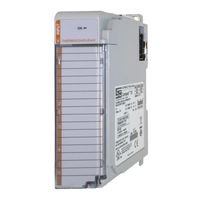
Spectrum Controls 1769 User Manual (82 pages)
6-Channel Isolated Thermocouple/mV Input Module
Brand: Spectrum Controls
|
Category: I/O Systems
|
Size: 2 MB
Table of Contents
Advertisement
Spectrum Controls 1769 User Manual (82 pages)
6 Channel Isolated Thermocouple/mV Input Module
Brand: Spectrum Controls
|
Category: I/O Systems
|
Size: 1 MB
Table of Contents

Spectrum Controls 1769 User Manual (74 pages)
6 Channel Isolated RTD/Resistance Input Module
Brand: Spectrum Controls
|
Category: I/O Systems
|
Size: 1 MB
Table of Contents
Advertisement

Spectrum Controls 1769 User Manual (72 pages)
6-channel Isolated RTD/Resistance Input Module
Brand: Spectrum Controls
|
Category: I/O Systems
|
Size: 2 MB