Spectrum Controls 1769 Series User Manual
6 channel isolated thermocouple/mv input module
Hide thumbs
Also See for 1769 Series:
- User manual (72 pages) ,
- User manual (82 pages) ,
- User manual (74 pages)

Related Manuals for Spectrum Controls 1769 Series


Summary of Contents for Spectrum Controls 1769 Series
- Page 1 User’s Manual Pub. 0300244-01 Rev. A 1769 6 Channel Isolated Thermocouple/mV Input Module Catalog Number: 1769sc-IT6I...
-
Page 2: Important Notes
No patent liability is assumed by Spectrum Controls with respect to the use of any of the information, products, circuits, programming, or services referenced herein. -
Page 3: Table Of Contents
Table of Contents IMPORTANT NOTES ............................... II NOTICE .................................. II LIMITED WARRANTY .............................. II PREFACE ................................VII CHAPTER 1 OVERVIEW ............................1-1 1.1 G ..........................1-1 ECTION ENERAL ESCRIPTION 1.1.1 Thermocouple/mV Inputs and Ranges ..................... 1-1 1.1.2 Data Formats ............................1-2 1.1.3 Filter Frequencies ............................. - Page 4 Compact™ IO Isolated Thermocouple Module 3.8 C ......................3-12 ECTION UNCTION OMPENSATION 3.9 C ............................3-13 ECTION ALIBRATION CHAPTER 4 MODULE DATA, STATUS, AND CHANNEL CONFIGURATION .............. 4-1 4.1 M ........................... 4-1 ECTION ODULE EMORY 4.2 C ........................... 4-2 ECTION ONFIGURING HANNELS 4.2.1 Configuration Data File ..........................
- Page 5 Table of Contents 5.5 N ....................5-3 ECTION CRITICAL VS RITICAL ODULE RRORS 5.6 M ......................5-4 ECTION ODULE RROR EFINITION ABLE 5.6.1 Module Error Field ............................ 5-4 5.6.2 Extended Error Information Field ......................5-4 5.7 E ............................5-5 ECTION RROR ODES 5.8 M...
- Page 6 Compact™ IO Isolated Thermocouple Module User’s Manual Pub. 0300244-01 Rev. A...
-
Page 7: Preface
Preface Read this preface to familiarize yourself with the rest of the manual. This preface covers the following topics: • Who should use this manual • How to use this manual • Related publications • Conventions used in this manual •... - Page 8 viii Compact™ IO Isolated Thermocouple Module Conventions Used in This Manual The following conventions are used throughout this manual: • Bulleted lists (like this one) provide information not procedural steps. • Numbered lists provide sequential steps or hierarchical information. • Italic type is used for emphasis •...
-
Page 9: Chapter 1 Overview
Chapter 1 Overview This chapter describes the 1769sc-IT6I Isolated Thermocouple/mV Input Module and explains how the module reads thermocouple or millivolt analog input data. Included is information about: • The module’s hardware and diagnostic features • An overview of system and module operation •... -
Page 10: Data Formats
Compact™ IO Isolated Thermocouple Module 1.1.2 Data Formats The data can be configured on board each module as: • Engineering units x 1 • Engineering units x 10 • Scaled-for-PID • Percent of full-scale • Raw/proportional data 1.1.3 Filter Frequencies The module uses a digital filter that provides high frequency noise rejection for the input signals. -
Page 11: General Diagnostic Features
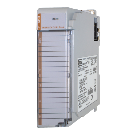
Chapter 1: Module Overview The illustration below shows the module’s hardware features. Item Description Bus lever Upper panel mounting tab Lower panel mounting tab Module status LED Module door with terminal identification label Movable bus connector (bus interface) with female pins Stationary bus connector (bus interface) with male pins Nameplate label Upper tongue-and-groove slots... -
Page 12: System Operation
Compact™ IO Isolated Thermocouple Module 1.2.1 System Operation At power-up, the module performs a check of its internal circuits, memory, and basic functions. During this time, the module status LED remains off. If no faults are found during power-up diagnostics, the module status LED is turned on. After power-up checks are complete, the module waits for valid channel configuration data. - Page 13 Chapter 1: Module Overview When configured for millivolt inputs, the module converts the analog values directly into digital counts. User’s Manual Pub. 0300244-01 Rev. A...
- Page 14 Compact™ IO Isolated Thermocouple Module User’s Manual Pub. 0300244-01 Rev. A...
-
Page 15: Chapter 2 Quick Start For Experienced Users
Chapter 2 Quick Start for Experienced Users Section 2.1 Before You Begin This chapter can help you to get started using the 1769sc-IT6I Isolated Thermocouple/mV Input Module. We base the procedures here on the assumption that you have an understanding of Allen-Bradley controllers. You should understand electronic process control and be able to interpret the ladder logic instructions required to generate the electronic signals that control your application. -
Page 16: Section 2.3 What You Need T O D O
Compact™ IO Isolated Thermocouple Module Section 2.3 What You Need To Do This chapter covers: 1) Ensuring that your power supply is adequate 2) Attaching and locking the module 3) Wiring the module 4) Configuring the module 5) Going through the startup procedure 6) Monitoring module operation Step 1: Ensure that your 1769 system Reference... - Page 17 Chapter 2: Quick Start for Experienced Users 1) Check that the bus lever of the module to be installed is in the unlocked (fully right) position. 2) Use the upper and lower tongue-and-groove slots (1) to secure the modules together (or to a controller). 3) Move the module back along the tongue-and-groove slots until the bus connectors (2) line up with each other.
- Page 18 Compact™ IO Isolated Thermocouple Module Follow the guidelines below when wiring the module. General • Power and input wiring must be in accordance with Class 1, Division 2 wiring methods, Article 501-4(b) of the National Electric Code, NFPA 70, and in accordance with the authority having jurisdiction.
- Page 19 Chapter 2: Quick Start for Experienced Users • Ground the shield drain wire at one end only. The preferred location is as follows. For grounded thermocouples or millivolt sensors, this is at the sensor end. For insulated/ungrounded thermocouples, this is at the module end. Contact your sensor manufacturer for additional details.
- Page 20 3) Put the controller in Run mode. During a normal start-up, the module status LED turns on. Note: If the module status LED does not turn on, cycle power. If the condition persists, contact your local distributor or Spectrum Controls for assistance. Step 6: Monitor the module status to Reference...
-
Page 21: Chapter 3 Installation And Wiring
Chapter 3 Installation and Wiring This chapter tells you how to: • Determine the power requirements for the modules • Avoid electrostatic damage • Install the module • Wire the module’s terminal block • Wire input devices Section 3.1 Compliance to European Union Directives This product is approved for installation within the European Union and EEA regions. -
Page 22: Section 3.2 Power Requirements
Compact™ IO Isolated Thermocouple Module Section 3.2 Power Requirements The module receives power through the bus interface from the +5V dc/+24V dc system power supply. The maximum current drawn by the module is shown in the table below. 5V dc 24V dc 150 mA 35 mA... -
Page 23: Prevent Electrical Discharge
Chapter 3: Installation and Wiring 3.3.2 Prevent Electrical Discharge Electrostatic discharge can damage integrated circuits or semiconductors if you touch analog I/O module bus connector pins or the terminal block on the input module. Follow these guidelines when Attention you handle the module: •... -
Page 24: Section 3.4 System Assembly
Compact™ IO Isolated Thermocouple Module which means that a module may not be located more than 8 modules away from the system power supply. Section 3.4 System Assembly The module can be attached to the controller or an adjacent I/O module before or after mounting. -
Page 25: Section 3.5 Mounting
Chapter 3: Installation and Wiring right-side adjacent module’s bus lever is in the unlocked (fully right) position. 3) Use the upper and lower tongue-and-groove slots (1) to secure the modules together (or to a controller). 4) Move the module back along the tongue-and-groove slots until the bus connectors (2) line up with each other. -
Page 26: Panel Mounting
Compact™ IO Isolated Thermocouple Module 3.5.2 Panel Mounting Mount the module to a panel using two screws per module. Use M4 or #8 panhead screws. Mounting screws are required on every module. Panel Mounting Using the Dimensional Template Panel Mounting Procedure Using Modules as a Template The following procedure allows you to use the assembled modules as a template for drilling holes in the panel. -
Page 27: Din Rail Mounting
Chapter 3: Installation and Wiring others aside. This reduces remounting time during drilling and tapping of the next group. 7) Repeat steps 1 to 6 for any remaining modules. 3.5.3 DIN Rail Mounting The module can be mounted using the following DIN rails: •... -
Page 28: System
Compact™ IO Isolated Thermocouple Module Section 3.7 Field Wiring Connections 3.7.1 System Wiring Guidelines Consider the following when wiring your system: General • Power and input wiring must be in accordance with Class 1, Division 2 wiring methods, Article 501-4(b) of the National Electric Code, NFPA 70, and in accordance with the authority having jurisdiction. -
Page 29: Terminal Door Label
Chapter 3: Installation and Wiring • This product is intended to be mounted to a well-grounded mounting surface such as a metal panel. Additional grounding connections from the module’s mounting tabs or DIN rail (if used) are not required unless the mounting surface cannot be grounded. -
Page 30: Wiring The Finger Safe Terminal Block
3-10 Compact™ IO Isolated Thermocouple Module 3.7.4 Wiring the Finger Safe Terminal Block When wiring the terminal block, keep the finger-safe cover in place. 1) Loosen the terminal screws to be wired. 2) Route the wire under the terminal pressure plate. You can use the bare wire or a spade lug. -
Page 31: Wiring The Module
Chapter 3: Installation and Wiring 3-11 3.7.5 Wiring the Module To prevent shock hazard, care should be taken when wiring the module to analog signal sources. Before wiring any module, disconnect power from the system power supply and from any other source to the module. Attention After the module is properly installed, follow the wiring procedure below, using the proper thermocouple extension cable, or Belden 8761 for non-thermocouple applications. -
Page 32: Section 3.8 Cold Junction Compensation
3-12 Compact™ IO Isolated Thermocouple Module Figure 3-1 (Wiring Diagram) CJC0+ Grounded Thermocouple IN0+ Ungrounded Thermocouple CJC0- IN0- IN3+ IN1+ IN3- IN1- IN4+ IN2+ IN4- IN2- IN5+ CJC1- IN5- CJC1+ Note: When using an ungrounded thermocouple, the shield must be connected to ground at the module end. -
Page 33: Section 3.9 Calibration
Chapter 3: Installation and Wiring 3-13 Section 3.9 Calibration The thermocouple module is initially calibrated at the factory. The module must be returned to the factory for calibration. User’s Manual Pub. 0300244-01 Rev. A... - Page 34 3-14 Compact™ IO Isolated Thermocouple Module User’s Manual Pub. 0300244-01 Rev. A...
-
Page 35: Chapter 4 Module Data, Status, And Channel Configuration
Chapter 4 Module Data, Status, and Channel Configuration After installing the 1769sc-IT6I Isolated Thermocouple/mV Input Module, you must configure it for operation, usually using the programming software compatible with the controller (for example, RSLogix 500 or RSLogix 5000). Once configuration is complete and reflected in the ladder logic, you need to operate the module and verify its configuration. -
Page 36: Section 4.2 Configuring Channels
Compact™ IO Isolated Thermocouple Module Note: Not all controllers support program access to the configuration file. Refer to your controller’s user manual. Section 4.2 Configuring Channels After module installation, you must configure operation details, such as thermocouple type, temperature units, etc., for each channel. Channel configuration data for the module is stored in the controller configuration file, which is both readable and writable. -
Page 37: Channel Configuration
Chapter 4: Module, Data, Status, and Channel Configuration 4.2.2 Channel Configuration Each channel configuration word consists of bit fields, the settings of which determine how the channel operates. See the table below and the descriptions that follow for valid configuration settings and their meanings. Table 4-2 (Channel Configuration) Filter Frequency 4.17 Hz... -
Page 38: Selecting Data Formats (Bits 12 Through 14)
Compact™ IO Isolated Thermocouple Module 4.2.4 Selecting Data Formats (Bits 12 through 14) This selection configures channels 0 through 5 to present analog data in any of the following formats: • Raw/Proportional Data • Engineering Units x 1 • Engineering Units x 10 •... -
Page 39: Engineering Units X1
Chapter 4: Module, Data, Status, and Channel Configuration selected. The raw/proportional data format also provides the best resolution of all the data formats. If you select the raw/proportional data format for a channel, the data word will be a number between -32767 and +32767. For example, if a type J thermocouple is selected, the lowest temperature of -210°C corresponds to -32767 counts. -
Page 40: Determining Open-Circuit Response (Bits 6 And 5)
Compact™ IO Isolated Thermocouple Module 4.2.7 Determining Open-Circuit Response (Bits 6 and 5) An open-circuit condition occurs when an input device or its extension wire is physically separated or open. This can happen if the wire is cut or disconnected from the terminal block. -
Page 41: Effects Of Filter Frequency On Noise Rejection
Chapter 4: Module, Data, Status, and Channel Configuration Table 4-6 (Filter Effects) Channel Update Channel Time Update (Ch 1 to 4) Time Normal During CJC NMRR NMRR Input Conversion Sample Cut-Off 50 Hz 60 Hz Filter Mode (Ch 0 & 5) Frequency Repeatability Rejection... -
Page 42: Repeatability
Compact™ IO Isolated Thermocouple Module Repeatability Repeatability is the ability of the input module to register the same reading in successive measurements for the same input signal. The repeatability for an input channel depends upon the filter frequency selected for that channel. Table 4-6, above, describes the repeatability for each of the range selections at the six available frequencies. -
Page 43: Section 4.3 Input Image File
Chapter 4: Module, Data, Status, and Channel Configuration All Channel enabled for thermocouple inputs Example 2 Channel (0 – 5) Input: Type J TC with 470 Hz Filter Module update time before CJC update = slowest channel update time = 8 ms Module update time during CJC update Channel 0 and 5 update time changes to 24ms = slowest channel update time... -
Page 44: Input Data Values
4-10 Compact™ IO Isolated Thermocouple Module Section 4.4 Input Data File The input data table allows you to access module read data for use in the control program, via word and bit access. The data table structure is shown in table below. Table 4-7 (Input Data File) Word/Bit Analog Input Data Channel 0... -
Page 45: Open-Circuit Flag Bits (Oc0 To Oc7)
Chapter 4: Module, Data, Status, and Channel Configuration 4-11 4.4.3 Open-Circuit Flag Bits (OC0 to OC7) Bits OC0 through OC5 of word 6 contain open-circuit error information for channels 0 through 5, respectively. Errors for the CJC sensors are indicated in OC6 and OC7. The bit is set (1) when an open-circuit condition exists. - Page 46 4-12 Compact™ IO Isolated Thermocouple Module User’s Manual Pub. 0300244-01 Rev. A...
-
Page 47: Chapter 5 Diagnostics And Troubleshooting
Chapter 5 Diagnostics and Troubleshooting This chapter describes troubleshooting the isolated thermocouple/mV input module. This chapter contains information on: • Safety considerations while troubleshooting • Internal diagnostics during module operation • Module errors Section 5.1 Safety Considerations Safety considerations are an important element of proper troubleshooting procedures. Actively thinking about the safety of yourself and others, as well as the condition of your equipment, is of primary importance. -
Page 48: Module Peration Vs . Channel Operation
Compact™ IO Isolated Thermocouple Module Circuits installed on the machine for safety reasons, like over-travel limit switches, stop push buttons, and interlocks, should always be hard-wired to the master control relay. These devices must be wired in series so that when any one device opens, the master control relay is de-energized, thereby removing power to the machine. -
Page 49: Over Or Under Range Detection
Chapter 5: Diagnostics and Troubleshooting Whenever a channel configuration word is improperly defined, the module reports an error. See pages 5-3 to 5-5 for a description of module errors. 5.4.2 Over or Under Range Detection Whenever the data received at the channel word is out of the defined operating range, an over-range or under-range error is indicated in input data word 7. -
Page 50: Table
Compact™ IO Isolated Thermocouple Module Section 5.6 Module Error Definition Table Analog module errors are expressed in two fields as four-digit Hex format with the most significant digit as “don’t care” and irrelevant. The two fields are “Module Error” and “Extended Error Information”. -
Page 51: Section 5.7 Error Codes
Chapter 5: Diagnostics and Troubleshooting If you set the fields in the configuration file to invalid or unsupported values, the module generates a critical error. Table 5-3 Extended Error Codes on page 5-5 lists the possible module-specific configuration error codes defined for the modules. Section 5.7 Error Codes The table below explains the extended error code. -
Page 52: Section 5.8 Module Inhibit Function
Compact™ IO Isolated Thermocouple Module Extended Error Module Information Code Error Error Type Error Description (Binary) Equivalent Code (Binary) X414 0 0001 0100 An unused bit has been set for ch1 (C:e.1) X415 0 0001 0101 An unused bit has been set for ch2 (C:e.2) X416 0 0001 0110 An unused bit has been set for ch3 (C:e.3) -
Page 53: Appendix A Specifications
Appendix A Specifications Specification Description Module ID Codes Vendor ID = 58 (Decimal) Product Type = 10 (Decimal) Product Code = 100 (Decimal) Configuration 6 isolated channels of thermocouple/millivolt inputs Input Modes Temperature or voltage Input Types Thermocouple types J, K, T, E, R, S, B, N, and L, and +/-50 mV and +/-100 mV Dimensions 118 mm (height) x 87 mm (depth) x 35 mm (width)height including mounting tabs is 138 mm4.65 in. - Page 54 Compact™ IO Isolated Thermocouple Module Thermocouple Type +/- 1 degrees C maximum @ 25 degrees C for 4.17 Hz, 10 Hz, 16.7 Hz, and 19.6 Hz filters. +/- 1.5 degrees C maximum @ 0 – 60°C for 4.17 Hz, 10 Hz, 16.7 Hz, and 19.6 Hz filters. N (-200°C to 1300°C) Thermocouple Type +/- 1.2 degrees C maximum @ 25°C for 4.17 Hz, 10 Hz, 16.7 Hz, and 19.6 Hz filters.
- Page 55 Appendix A: Specifications Thermocouple Type B +/- 0.7°C Thermocouple Type C +/- 0.2°C Millivolt Inputs +/- 6.0 microvolts Data formats Eng units, Eng units X10, Scaled for PID, Prop. Counts, Percent of Full Scale Input Filter 4.17 Hz, 10 Hz, 16.7 Hz, 19.6 Hz, 62 Hz and 470 Hz Channel Update Time See Module Update Time on page 4-8 Module or Single Channel...
- Page 56 Compact™ IO Isolated Thermocouple Module User’s Manual Pub. 0300244-01 Rev. A...
-
Page 57: Appendix B Using Thermocouple Junctions
Appendix B Using Thermocouple Junctions This appendix describes the types of thermocouple junctions available, and explains the trade-offs in using them with the 1769sc-IT6I Isolated thermocouple/mV analog input module. Take care when choosing a thermocouple junction, and connecting it from the environment to the module. If you do not take adequate precautions for a given thermocouple type, the electrical isolation of the Attention module might be compromised. - Page 58 1769sc-IT6I Spectrum Controls recommends that a grounded junction thermocouple have a protective sheath made of electrically insulated material (for example, ceramic). An alternative is to float the metal sheath with respect to any path to chassis ground or to another thermocouple metal sheath.
-
Page 59: Section B.3 Using An Exposed Junction Thermocouple
Appendix B: Using Thermocouple Junctions Section B.3 Using an Exposed Junction Thermocouple An exposed junction thermocouple uses a measuring junction that does not have a protective metal sheath. A thermocouple with this junction type provides the fastest response time but leaves thermocouple wires unprotected against corrosive or mechanical damage. - Page 60 Compact™ IO Isolated Thermocouple Module To prevent violation of channel-to-channel isolation: • For multiple exposed junction thermocouples, do not allow the measuring junctions to make direct contact with electrically conductive process material. • Preferably use a single exposed junction thermocouple with multiple ungrounded junction thermocouples.
-
Page 61: Appendix C Module Configuration Using Micrologix 1500 And Rslogix 500
Appendix C Module Configuration Using MicroLogix 1500 and RSLogix 500 This appendix examines the 1769sc-IT6I module’s addressing scheme and describes module configuration using RSLogix 500 and a MicroLogix 1500 controller. Section C.1 Module Addressing The following memory map shows the input and configuration image tables for the module. -
Page 62: 1769Sc-It6I Configuration File
Compact™ IO Isolated Thermocouple Module For example, to obtain the general status of channel 2 of the module located in slot e, use address I:e.6/2. Note: The end-cap does not use a slot address. C.1.1 1769sc-IT6I Configuration File The configuration file contains information you use to define the way a specific channel functions. - Page 63 Appendix C: Module Configuration Using MicroLogix 1500 and RSLogix 500 Start RSLogix and create a MicroLogix 1500 application. The following screen appears: While offline, double-click on the IO Configuration icon under the controller folder and the following IO Configuration screen appears. This screen allows you to manually enter expansion modules into expansion slots, or to automatically read the configuration of the controller.
- Page 64 Compact™ IO Isolated Thermocouple Module Enter the settings from the table below. Table C-2 (Module ID Codes) Vendor ID Product Type Product Code Series Input Words Output Words Extra Data Length After entering the data from the table above, the screen should look like the one shown below.
- Page 65 Appendix C: Module Configuration Using MicroLogix 1500 and RSLogix 500 Enter the decimal equivalent of each configuration word. There are a total of 13 words that need to be configured. The module default settings are used if all the configuration words are left at zero.
- Page 66 Compact™ IO Isolated Thermocouple Module User’s Manual Pub. 0300244-01 Rev. A...
-
Page 67: Appendix D Configuring The It6I For Compactlogix Controllers In Rslogix 5000
Appendix D Configuring the IT6I for CompactLogix Controllers in RSLogix 5000 The procedure in this example is used only when your 1769sc-IT6I Isolated Thermocouple module add-on profile is not available. An add-on profile for the 1769sc- IT6I will be made available on our website (www.spectrumcontrols.com) after the initial release of the module. - Page 68 Compact™ IO Isolated Thermocouple Module In the Controller Organizer on the left of the screen, right click on “CompactBus Local”, select New Module, and the following screen appears: This screen is used to narrow your search for I/O modules to configure into your system. From the list select the “Generic 1769 Module”.
- Page 69 Appendix D: Configuring the IT6I for CompactLogix Controllers in RSLogix 5000 First, select the Comm Format (“Input Data – INT” for the 1769sc-IT6I), then fill in the name field. For this example, “IT6I” is used to help identify the module type in the Controller Organizer.
-
Page 70: Section D.3 Configuring I/O Modules
Compact™ IO Isolated Thermocouple Module At this point you may click “Finish” to complete the configuration of your I/O module. Configure each I/O module in this manner. Section D.3 Configuring I/O Modules Once you have created a Generic Profile for 1769sc-IT6I Isolated Thermocouple module, you must enter configuration information into the tag database that is automatically created from the Generic Profile information you entered. -
Page 71: Thermocouple
Appendix D: Configuring the IT6I for CompactLogix Controllers in RSLogix 5000 Section D.4 Configuring a 1769sc-IT6I Isolated Thermocouple Module To configure the 1769sc-IT6I module in slot 1, click on the plus sign left of Local:1:C. Configuration data is entered under the Local:1:C.Data tag. Click the plus sign to the left of Local:1:C.Data to reveal the 13 integer data words where configuration data may be entered for the 1769sc-IT6I module. - Page 72 Compact™ IO Isolated Thermocouple Module User’s Manual Pub. 0300244-01 Rev. A...
-
Page 73: Appendix E Configuring The It6I To Be Used With A 1769-Adn Devicenet Adapter
Appendix E Configuring the IT6I to be Used with a 1769-ADN DeviceNet Adapter This application example assumes your 1769sc-IT6I isolated thermocouple input module is in a remote DeviceNet system controlled by a 1769-ADN DeviceNet adapter. RSNetworx for DeviceNet is not only used to configure your DeviceNet network, but is also used to configure individual I/O modules in remote DeviceNet adapter systems. - Page 74 Compact™ IO Isolated Thermocouple Module Start RSNetworx for DeviceNet. The following screen appears: In the left column under Category, click on the “+” sign next to Communication Adapters. The list of products under Communication Adapters contains the 1769- ADN/A. Should this adapter not appear under Communication Adapters, your RSNetworx for DeviceNet software is not version 6.00 or later.
-
Page 75: Sc -It6I
Appendix E: Configuring the IT6I to be Used with a 1769-AND DeviceNet Adapter To configure I/O for the adapter, double-click on the adapter that you just placed on the network, and the following screen appears: At this point, you may modify the adapters DeviceNet node address, if desired. Next, click on the Module Configuration tab. - Page 76 Compact™ IO Isolated Thermocouple Module double-click on the first empty slot after the 1769-ADN. From the module list on the left, select the 1769sc-IT6I. The module should appear in the empty slot. Double-click on the 1769sc-IT6I module in slot 1 and the following 1769sc-IT6I configuration screen appears: Enter 1 into the bank field at the bottom of the screen.
- Page 77 Appendix E: Configuring the IT6I to be Used with a 1769-AND DeviceNet Adapter Click OK and your configuration for the 1769sc-IT6I isolated thermocouple input module is complete. Refer to your Compact™ I/O 1769-ADN DeviceNet Adapter user’s manual, publication number 1769-UM001A-US-P, for information concerning DeviceNet network configuration and operation.
- Page 78 Compact™ IO Isolated Thermocouple Module User’s Manual Pub. 0300244-01 Rev. A...
- Page 79 Index Accuracy, A-1 Indicator Lights, 5-1 Input Ranges, 1-1 Types, 1-1 Calibration, 3-13 Input Data File, 4-10 Channel Configuration, 4-3 Input Filter Selection, 4-6 Cold Junction Compensation, 3-12 CompactLogix, D-1 Configuration Data File, 4-2 Critical Module Error, 5-3 LED, 1-4, 5-1, 5-2 Cut-Off Frequency, 4-7 Low Voltage Directive, 3-1 Data Format, 1-2...
- Page 80 Wiring Finger Safe, 3-10 Raw/Proportional Data, 4-4 Repeatability, 4-8, A-2 Under Range RSLogix 500, C-1 Status, 4-11 RSLogix 5000, D-1 Under-Range Detection, 5-3 Ungrounded Junction, B-2 Scaled for PID, 4-5 Update Time Specifications, A-1 Channel, 4-6 System Assembly, 3-4 Module, 4-8 System Operation, 1-4 Wiring Diagram, 3-12 Terminal Block, 2-4, 3-8...
- Page 81 In the unlikely event that the module should need to be returned to Spectrum Controls, please ensure that the unit is enclosed in approved ESD packaging (such as static-shielding / metalized bag or black conductive container).
- Page 82 ©2009, Spectrum Controls, Inc. All rights reserved. Specifications subject to change without notice. The Encompass logo and ControlLogix are trademarks of Rockwell Automation. Corporate Headquarters Spectrum Controls Inc. P.O. Box 5533 Bellevue, WA 98006 USA Fax: 425-641-9473 Tel: 425-746-9481 Web Site: www.spectrumcontrols.com E-mail: spectrum@spectrumcontrols.com...
Need help?
Do you have a question about the 1769 Series and is the answer not in the manual?
Questions and answers