Sign In
Upload
Manuals
Brands
Spectrum Controls Manuals
I/O Systems
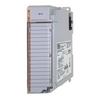
1769sc-IT6I
Spectrum Controls 1769sc-IT6I Manuals
Manuals and User Guides for Spectrum Controls 1769sc-IT6I. We have
2
Spectrum Controls 1769sc-IT6I manuals available for free PDF download: User Manual
Spectrum Controls 1769sc-IT6I User Manual (82 pages)
6-Channel Isolated Thermocouple/mV Input Module
Brand:
Spectrum Controls
| Category:
I/O Systems
| Size: 2 MB
Table of Contents
Important Notes
2
Table of Contents
3
Chapter 1 Module Overview
9
Section 1.1 General Description
9
Thermocouple/MV Inputs and Ranges
9
Data Formats
10
Filter Frequencies
10
Hardware Features
10
General Diagnostic Features
11
Section 1.2 System Overview
11
System Operation
11
Module Operation
11
Chapter 2 Installation and Wiring
13
Section 2.1 before You Begin
13
Section 2.2 Required Tools and Equipment
13
Section 2.3 Compliance to European Union Directives
13
EMC Directive
13
Low Voltage Directive
14
Section 2.5 Power Requirements
14
Section 2.6 General Considerations
14
Hazardous Location Considerations
14
Prevent Electrical Discharge
15
Remove Power
16
Selecting a Location
16
Power Supply Distance
16
Reducing Noise
16
Section 2.7 Mounting
17
Minimum Spacing
17
Parts List
18
Panel Mounting
20
Panel Mounting Procedure Using Modules as a Template
21
Panel Mounting Using the Dimensional Template
21
DIN Rail Mounting
22
Replacing a Single Module Within a System
22
Section 2.8 Wiring the Module
22
General
22
Terminal Block
23
Grounding
23
Noise Prevention
24
Terminal Door Label
24
Removing and Replacing the Terminal Block
24
Wiring the Finger Safe Terminal Block
25
Wire Size and Terminal Screw Torque
26
Wiring Diagram
28
Section 2.9 Cold Junction Compensation
28
Section 2.10 Calibration
29
Chapter 3 Module Data, Status, and Channel Configuration
31
Section 3.1 Module Memory Map
31
Section 3.2 Configuring Channels
32
Configuration Data File
32
Channel Configuration
33
Unused
33
Channel Display
33
Enabling or Disabling a Channel (Bit 15)
34
Selecting Data Formats (Bits 12 through 14)
35
Raw/Proportional Data
35
Engineering Units X1
36
Engineering Units ×10
36
Percent Range
36
Scaled for PID
36
Selecting Input Type (Bits 8 through 11)
36
Determining Open-Circuit Response (Bits 6 and 5)
37
Selecting Temperature Units (Bit 7)
37
Cut-Off Frequency
38
Display CJC Data (Bit 4)
38
Effects of Filter Frequency on Noise Rejection
38
Selecting Input Filter Frequency (Bits 0 through 2)
38
Module Update Time
39
Repeatability
39
Section 3.3 Input Image File
41
Input Data Values
41
General Status Bits (S0 to S7)
41
Input Data Not Valid Condition
41
Open-Circuit Flag Bits (OC0 to OC7)
42
Over-Range Flag Bits (O0 to O7)
42
Under Range Flag Bits (U0 to U7)
42
Chapter 4 Diagnostics and Troubleshooting
43
Section 4.1 Safety Considerations
43
Indicator Lights
43
Stand Clear of Equipment
43
Program Alteration
43
Safety Circuits
44
Module Peration Vs . Channel Operation
44
Diagnostics
44
Section 4.4 Channel Diagnostics
44
Invalid Channel Configuration Detection
45
Over or under Range Detection
45
Open Circuit Detection
45
Non-Critical Vs
45
Errors
45
Section 4.6 Module Error Definition Table
46
Module Error Field
46
Extended Error Information Field
46
Configuration Errors
47
Hardware Errors
47
Section 4.7 Error Codes
47
Module
48
Function
48
Appendix A Specifications
51
Appendix B Using Thermocouple Junctions
57
Section B.1 Using a Grounded Junction Thermocouple
57
Ungrounded
58
Thermocouple
58
Section B.3 Using an Exposed Junction Thermocouple
59
Appendix C Module Configuration Using Micrologix 1500 and Rslogix 500
63
Appendix D Configuring the It6I for Compactlogix Controllers in Rslogix 5000
67
Section D.3 Configuring I/O Modules
70
Thermocouple
71
Odule
71
Appendix E Configuring the It6I to be Used with a 1769-Adn Devicenet Adapter
73
Sc -It6I
75
Advertisement
Spectrum Controls 1769sc-IT6I User Manual (82 pages)
6 Channel Isolated Thermocouple/mV Input Module
Brand:
Spectrum Controls
| Category:
I/O Systems
| Size: 1 MB
Table of Contents
Important Notes
2
Notice
2
Table of Contents
3
Limited Warranty
2
Preface
7
Chapter 1 Overview
9
Section 1.1 General Description
9
Thermocouple/MV Inputs and Ranges
9
Data Formats
10
Filter Frequencies
10
Hardware Features
10
General Diagnostic Features
11
Section 1.2 System Overview
11
System Operation
12
Module Operation
12
Chapter 2 Quick Start for Experienced Users
15
Section 2.1 before You Begin
15
Section 2.2 Required Tools and Equipment
15
Section 2.3 What You Need T O D O
16
Chapter 3 Installation and Wiring
21
Section 3.1 Compliance to European Union Directives
21
EMC Directive
21
Low Voltage Directive
21
Section 3.2 Power Requirements
22
Section 3.3 General Considerations
22
Hazardous Location Considerations
22
Prevent Electrical Discharge
23
Remove Power
23
Selecting a Location
23
Section 3.4 System Assembly
24
Section 3.5 Mounting
25
Minimum Spacing
25
Panel Mounting
26
DIN Rail Mounting
27
System
28
Section 3.7 Field Wiring Connections
28
System Wiring Guidelines
28
Terminal Door Label
29
Removing and Replacing the Terminal Block
29
Wiring the Finger Safe Terminal Block
30
Wiring the Module
31
Section 3.8 Cold Junction Compensation
32
Section 3.9 Calibration
33
Chapter 4 Module Data, Status, and Channel Configuration
35
Section 4.1 Module Memory Map
35
Section 4.2 Configuring Channels
36
Configuration Data File
36
Channel Configuration
37
Unused
37
Channel Display
37
Enabling or Disabling a Channel (Bit 15)
37
Selecting Data Formats (Bits 12 through 14)
38
Data Format
38
Raw/Proportional Data
38
Engineering Units X1
39
Engineering Units X10
39
Scaled for PID
39
Percent Range
39
Selecting Input Type (Bits 8 through 11)
39
Selecting Temperature Units (Bit 7)
39
Determining Open-Circuit Response (Bits 6 and 5)
40
Display CJC Data (Bit 4)
40
Selecting Input Filter Frequency (Bits 0 through 2)
40
Effects of Filter Frequency on Noise Rejection
41
Cut-Off Frequency
41
Repeatability
42
Module Update Time
42
Section 4.3 Input Image File
43
Input
43
File
43
Input Data Values
44
General Status Bits (S0 to S7)
44
Open-Circuit Flag Bits (OC0 to OC7)
45
Over-Range Flag Bits (O0 to O7)
45
Under Range Flag Bits (U0 to U7)
45
Chapter 5 Diagnostics and Troubleshooting
47
Section 5.1 Safety Considerations
47
Indicator Lights
47
Stand Clear of Equipment
47
Program Alteration
47
Safety Circuits
47
Module Peration Vs . Channel Operation
48
P Diagnostics
48
Section 5.4 Channel Diagnostics
48
Invalid Channel Configuration Detection
48
Over or under Range Detection
49
Open Circuit Detection
49
Non-Critical Vs
49
Errors
49
Table
50
Module Error Field
50
Extended Error Information Field
50
Section 5.7 Error Codes
51
Section 5.8 Module Inhibit Function
52
Appendix A Specifications
53
Appendix B Using Thermocouple Junctions
57
Section B.1 Using a Grounded Junction Thermocouple
57
Junction Thermocouple
57
Section B.3 Using an Exposed Junction Thermocouple
59
Appendix C Module Configuration Using Micrologix 1500 and Rslogix 500
61
Module Addressing
61
1769Sc-IT6I Configuration File
62
Section C.2 Configuring the 1769 Sc -It6I in a Micro Logix 1500 System
62
Appendix D Configuring the It6I for Compactlogix Controllers in Rslogix 5000
67
Section D.3 Configuring I/O Modules
70
Thermocouple
71
Odule
71
Appendix E Configuring the It6I to be Used with a 1769-Adn Devicenet Adapter
73
Sc -It6I
75
Advertisement
Related Products
Spectrum Controls 1769sc-IF4IH
Spectrum Controls 1769sc-IT6IK
Spectrum Controls 1769sc-IR6I
Spectrum Controls 1734
Spectrum Controls 1769
Spectrum Controls 1746sc-CTR4
Spectrum Controls 1762sc-IF4OF4
Spectrum Controls 1762sc-OF8
Spectrum Controls 1746sc-INI4i
Spectrum Controls 1794sc-IF8IU
Spectrum Controls Categories
Control Unit
I/O Systems
Monitor
Gateway
More Spectrum Controls Manuals
Login
Sign In
OR
Sign in with Facebook
Sign in with Google
Upload manual
Upload from disk
Upload from URL