Sign In
Upload
Manuals
Brands
Nuvo Manuals
Telephone Accessories
Navigator Lift 250 Single
Nuvo Navigator Lift 250 Single Manuals
Manuals and User Guides for Nuvo Navigator Lift 250 Single. We have
1
Nuvo Navigator Lift 250 Single manual available for free PDF download: Installation Instructions Manual
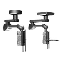
Nuvo Navigator Lift 250 Single Installation Instructions Manual (96 pages)
Brand:
Nuvo
| Category:
Telephone Accessories
| Size: 11.24 MB
Table of Contents
Table of Contents
4
1 Versions, Scope of Delivery and Installation References
8
Overview of the Pendant System
8
Scope of Delivery of the Motor Arm, Navigator Lift ™ 150 / 250 Single Arm
9
Overview of the Pendant System
10
Scope of Delivery of the Extension Arm with Motor Arm
11
Overview of the Pendant System
12
Scope of Delivery of the XL Extension Arm with Motor Arm
13
Overview of the Optional Accessories
14
Scope of Delivery of the Optional Accessories
15
Further Optional Accessories
15
2 Safety Instructions
16
Approved Nuvo Products
16
Combination with Products of Other Manufacturers
16
Structure of the Safety Instructions
16
Warnings of Risk of Injury
16
Warnings of Damage to Property
16
Indication of Additional Information
16
Supplementary Symbols Used in the Safety Instructions
17
Description of Graphic Symbols Possibly Used on the Appliance and the Package
17
Intended Purpose
18
Incorrect Use
18
Contraindications
18
Ambient Conditions
19
Ambient Conditions for Storage and Transport
19
Ambient Conditions for Operation
19
Information on the Rating Plate
19
Retrofit to an Already Installed Ceiling Mount
20
Overview of the most Important Safety Instructions
20
Proper Use of Oxygen
21
Warranty
21
Disposal
21
3 Further Applicable Installation Instructions
22
4 Installation Equipment Required
23
5 Load Data
24
Load Data of the Single Version
24
Load Data for Support Arm Combinations
24
6 Mounting Threaded Bolts to the Interface Plate
25
Mounting Situation: Mounting the Interface Plate to the Raw Ceiling Without Intermediate Ceiling
25
Versions
25
Cutting the Threaded Bolts to Length
25
Mounting the Threaded Bolts
25
Mounting the Upper Insulations to the Threaded Bolts
26
Mounting Situation: Interface Plate on the Intermediate Ceiling Mount
27
Versions
27
Cutting the Threaded Bolts to Length
27
Mounting the Threaded Bolts to the Single / Duo Interface Plate
28
Mounting the Upper Insulations to the Threaded Bolts
29
Mounting Situation: Interface Plate on the Intermediate Ceiling Mount
30
Versions
30
Mounting the Threaded Bolts
30
Mounting the Upper Insulations to the Threaded Bolts
31
7 Pre-Assembly: Mounting an Extended Ceiling Tube
32
Components Described in this Chapter
32
Mounting an Extended Ceiling Tube
33
Mounting a Ceiling Tube
33
Mounting the Strain Relieving Mechanism in the Ceiling Tube
34
Subsequently Mounting the Earthing Cable to the Ceiling Tube
35
8 Mounting the Ceiling Tube to the Threaded Bolts of the Interface Plate
36
Components Described in this Chapter
36
Mounting a Ceiling Tube
37
Aligning the Motor Arm / Extension Arm with the Interface Plate, Single
38
Aligning the Motor Arm / Extension Arm with the Interface Plate, Duo
40
9 Mounting the Console Tube to the Motor Arm
42
Components Described in this Chapter
42
Mounting the Console Tube to the Motor Arm
43
Positioning the Navigator M6 under the Console Tube
43
10 Mounting Optional Accessories
44
Mounting the Extension Arm Lighting (for Retrofit Only)
44
Mounting the Brake Indicators (for Retrofit Only)
45
11 Mounting Cables
46
Versions
46
Safety Instructions
46
Swinging out / Retracting the Electronic Unit
47
Swinging out the Electronic Unit
47
Retracting the Electronic Unit
47
Connecting Cables to the Extension Arm with Motor Arm Dual Arm, with Navigator M6
48
Routing the Cables from the Distributor Board to the DC/DC Converter
48
Routing the Cables from the Main Board to the DC/DC Converter
48
Connecting the Motor and the End Switch of the Height Adjustment Mechanism
48
Connecting the Control Cable of the Brakes and the Height Adjustment Mechanism
48
Connecting the Electromagnetic Brakes
48
Mounting the Power Cable
48
Connecting Optional Accessories to the Extension Arm with Motor Arm Dual Arm, with Navigator M6
50
Connecting the Optional Brake Indicators
50
Connecting an Optional Sound or Lighting Cable
50
Connecting the Optional Extension Arm Lighting
50
Connecting Earthing Cables to the Extension Arm with Motor Arm Dual Arm, with Navigator M6
52
Routing the Supply Cables and Hoses through the Extension Arm with Motor Arm Dual Arm, with Navigator M6
52
Connecting the Cables to the Motor Arm Single Arm, with Navigator M6
54
Routing the Cables from the Main Board to the DC/DC Converter
54
Connecting the Motor and the End Switch of the Height Adjustment Mechanism
54
Connecting the Control Cable of the Brakes and the Height Adjustment Mechanism
54
Connecting the Electromagnetic Brake
54
Mounting the Power Cable
54
Connecting the Optional Accessories to the Motor Arm Single Arm, with Navigator M6
56
Connecting an Optional Brake Indicator
56
Connecting an Optional Sound or Lighting Cable
56
Connecting the Earthing Cables to the Motor Arm Single Arm, with Navigator M6
58
Routing the Supply Cables and Hoses through the Motor Arm Single Arm, with Navigator M6
58
12 Connecting the Supply Cables and Hoses
60
Safety Instructions
60
Installing Gas Supply Hoses and Exhaust Air Ducts
61
Connecting the Earthing Cables
62
Installing the Voltage Selection Plug and Connecting the Power Cables
62
Installing the Voltage Selection Plug for the 120V / 230V Power Supply
62
Replacing the Fuse
63
Connecting Power Cables
64
Checking the Supply Cables and Hoses
64
13 Inspections
65
Gas Inspection (Only Navigator M6)
65
Mechanical Collision Test
65
14 Mounting the Canopy, Cover Caps and the Cover Panels
66
Mounting a Single / Duo Canopy
66
Preparing the Installation of the Canopy
66
Mounting the Canopy Halves
66
Mounting the Single Canopy
67
Preparing the Installation of the Canopy
67
Mounting the Canopy Halves
67
Mounting/Dismantling the Cover Caps To/From the Extension Arm
68
Mounting the Cover Caps
68
Dismantling the Cover Caps
68
Mounting the Cover Plates to the Motor Arm
69
Inserting the Rear Cover Plates
69
Mounting the Front Cover Plates
69
Mounting the Rear Side Panels to the Motor Arm
70
Mounting the Lower, Rear Covers to the Motor Arm
70
Mounting the Front Side Panels to the Motor Arm
71
Mounting the Front Upper Cover to the Motor Arm
71
15 Adjustments
72
General Safety Instructions
72
Adjusting the Mechanical Brake for the Navigator M6
72
Adjusting the Vertical Lift on the Motor Arm
73
Functioning of the Vertical Lift
73
Opening the Bottom Rear Cover
73
Adjusting the Vertical Lift
74
Shutting the Bottom Rear Cover
74
Correcting the Vertical Alignment of the Navigator M6
75
Opening the Bottom Rear Cover
75
Correcting the Vertical Alignment
75
Shutting the Bottom Rear Cover
75
Condition of the Swivel Stop on the Extension Arm and the Motor Arm Supplied
76
Extension Arm and Motor Arm with Pre-Assembled Swivel Stop
76
Extension Arm and Motor Arm Without Pre-Assembled Swivel Stop
76
Adjusting the Swivel Stop on the Extension Arm and Motor Arm
77
Versions
77
Tool to be Used
77
Mounting the Swivel Stop
78
Dismantling the Swivel Stop
79
16 Initial and Repeated Commissioning and Handover
80
17 Technical Description
81
18 Technical Data
84
19 Electromagnetic Compatibility (EMC) Information
87
Guidelines and Manufacturer's Declarations
87
Electromagnetic Emissions
87
Electromagnetic Immunity
88
Test Specifications
90
20 Approved Nuvo Products
92
21 Optional Accessories
92
22 Possible Combination with Third-Party Products
92
Notes
93
Advertisement
Advertisement
Related Products
Nuvo Navigator Lift 150 Single
Nuvo Navigator Lift 150 Dual
Nuvo Navigator Lift 180 Single
Nuvo Navigator Lift 180 Dual
Nuvo Navigator Lift 180 Air Plus-Single
Nuvo Navigator Lift 180 XL Dual
Nuvo Navigator Lift XL 250 Dual
Nuvo Categories
Amplifier
Speakers
Stereo System
Tuner
Docking Station
More Nuvo Manuals
Login
Sign In
OR
Sign in with Facebook
Sign in with Google
Upload manual
Upload from disk
Upload from URL