Sign In
Upload
Manuals
Brands
Mircom Manuals
Control Panel
FR-320 Series
Mircom FR-320 Series Manuals
Manuals and User Guides for Mircom FR-320 Series. We have
2
Mircom FR-320 Series manuals available for free PDF download: Installation And Operation Manual
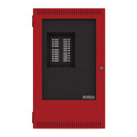
Mircom FR-320 Series Installation And Operation Manual (112 pages)
Pre-Action/Deluge and Agent Release Control Panel
Brand:
Mircom
| Category:
Control Panel
| Size: 8 MB
Table of Contents
Table of Contents
3
1 FCC Notice
11
Notice for All FR-320 Series Built-In Udacts Sold in the U.S.A
11
2 Introduction
13
Panel Type
13
Deluge Sprinkler System
13
Pre-Action Sprinkler System
13
Agent Release System
13
Overall Features
13
3 Conventions
15
Circuits
15
Zone
15
Display Points
15
Wiring Styles
15
4 System Components
16
Main Pre-Action/Deluge and Agent Release Control Panel
16
Figure 1 FR-320 Panel
16
Relay Modules: Six Relays
17
Polarity Reversal/City Tie
17
Smart Relay Module
17
Input Class a Converter: Six Circuits
17
Output Class a Converter: Two Circuits
18
Ancillary Annunciator
18
Active End-Of-Line
18
Additional System Accessories
18
5 Mechanical Installation
19
Installing the Enclosure
19
Figure 2 Box Dimensions, Semi-Flush Mounting and Trim Ring
19
BBX-1024DS and BBX-1024DSR Mechanical Installation
20
Figure 3 Flush Trim Detail
20
Figure 4 BBX-1024DS and BBX-1024DSR Installation Instructions and Dimensions
21
Installing the Adder Modules
22
Figure 5 Installation of Adder Modules
22
6 Cable and Jumper Connections for Main Board, Core Board and Adder Modules
23
Main Pre-Action/Deluge and Agent Release Control Board
23
Figure 6 Main Control Board Cable Connector and Jumper Settings
23
Connectors and Jumpers on the Main Fire Alarm Board
24
Connectors and Jumpers on the Core Board
24
ICAC-306 Input Class-A Converter Adder Module
24
Figure 7 ICAC-306 Input Class-A Converter Adder Module
24
OCAC-302 Output Class-A Converter Adder Module
25
Relay Adder Module
25
Figure 8 OCAC-302 Output Class-A Converter Adder Module
25
Figure 9 RM-306 Six Relay Adder Module
25
Jumpers
26
Correlations
26
Polarity Reversal and City Tie Module (Model PR-300)
26
Jumper Settings
26
Figure 10 Polarity Reversal and City Tie Module
26
7 Field Wiring
27
Main Board Field Wiring
27
Initiating Circuit Wiring
27
Figure 11 Initiating Circuit - Class B or Style B Wiring
27
Table 1 Settings Permitted in CAN/ULCS527
27
Table 7 Settings Permitted in CAN/ULCS527
27
Abort and Manual Release Switch Wiring
28
Figure 12 Initiating Circuit- Class a or Style D Wiring
28
Figure 13 Abort and Manual Release Switch Class B or Style B Wiring
28
Figure 14 Abort and Manual Release Switch Class a or Style D Wiring
29
Indicating Circuit Wiring
30
Figure 15 Indicating Circuit - Class B or Style y Wiring
30
Figure 16 Indicating Circuit -Class a or Style Z Wiring
30
Releasing Circuit Wiring
31
Dialer Wiring (US Only)
31
Figure 17 Releasing Circuit Wiring
31
Figure 18 Dialer Wiring
31
Four-Wire Smoke Detector Wiring
32
Relay Adder Module Wiring
32
Figure 19 Four-Wire Smoke Detector Wiring
32
Figure 20 Relay Per Zone (RM-306) Terminal Connection
32
Polarity Reversal and City Tie Module (PR-300) Wiring
33
Figure 21 Polarity Reversal and City Tie Module Terminal Connection
33
Power Supply Connection
34
Figure 22 Power Supply Connection
34
Table 2 Power Supply Ratings
34
Wiring Tables and Information
35
Four-Wire Smoke Power (Regulated)
35
Table 3 Initiating Circuit Wiring Distances
35
Table 4 Indicating Circuit Wiring Distances
35
Supervised Auxiliary Power (Regulated)
36
Unfiltered Supply (Full Wave Rectified)
36
8 System Checkout
37
Before Turning the Power "ON
37
Power-Up Procedure
37
Troubleshooting
38
Table 5 Troubleshooting
38
9 Indicators, Controls and Operations
39
Figure 23 LED Indicators and Control Buttons
39
Common LED Indicators
40
AC on
40
Common Alarm
40
Common Trouble
40
Battery Trouble
40
Remote Trouble
40
Ground Fault
40
CPU Fail
40
Abort
40
Released
40
ALM/SUP/TBL/BLDG AUDIBLE SIL (Buzzer Silence)
41
Pre Release
41
Menu Buttons
41
Switches and Common Indicators
41
Zone 1 to Zone 4
41
Zone 5 and Zone 6
41
Out1 and Out2 (NAC Circuits)
42
Out3 and Out4 (Releasing Circuits)
42
Input Circuits Bypass Switch
42
Output Circuits Bypass Switch
42
Common Controls
42
System Reset Button
42
Signal Silence Button
42
Auxiliary Disconnect Button
42
Lamp Test Button
43
ALM/SUP/TBL/BLDG AUDIBLE SIL Button (Buzzer Silence)
43
Circuit (Zone) Disconnect Buttons
43
Common Relays
44
Circuit Types
44
Initiating (Detection) Circuit Types
44
Non-Verified Alarm
44
Water Flow Alarm (Water Flow Sensors)
44
Non-Latching Supervisory (for Supervisory Circuits)
44
Table 6 Relay Types
44
Latching Supervisory (for Supervisory Devices)
45
Abort Switch
45
Manual Release Switch
45
Indicating (Signal) Circuits Types
45
Silenceable Signal
45
Non-Silenceable Signal
45
Silenceable Strobe
45
Non-Silenceable Strobes
45
Evacuation Codes
46
Figure 24 Evacuation and Alert Codes
46
10 Configuration
47
Table 8 Settings Permitted in UL864
47
Using the CFG-300 Tool
48
Entering the Passcode
48
Figure 25 FR-320 Configuration
48
How to Use the Keypad to Program the
49
Table 9 Access Levels
49
Command Menu
50
Figure 26 Command Menu
50
Panel Config (Command-Menu)
51
Command Menu-->Panel Config-->Choose a Mode
51
Command Menu-->Panel Config-->Hazard Config
52
Set Time (Command-Menu)
56
Command Menu-->Panel Config-->Default Config
56
View Event Log (Command-Menu)
58
Print Event Log
58
Clear Event Log (Command-Menu)
59
Dialer Config (Command-Menu)
59
Account Info
60
Telephone Line
61
Report Options
62
Time Parameters
63
Dialer Enable/Disable
64
Test Dialer (Command-Menu)
65
Dialer Test Messages
65
Exit (Command-Menu)
66
11 Operating the Panel
67
Panel Operation During Various Hazard States
67
Hazard Idle
67
Hazard Alert (or Equivalently First Alarm in Cross-Zoned Application)
67
Hazard Alarm (Pre-Discharge, or Equivalently Second Alarm in Cross-Zoned Application)
67
Hazard Release
68
General Panel Operation
68
12 Pre-Programmed Modes
69
Mode 1: Agent Release, Single Hazard, Cross-Zoned, Combined Release
69
Zone Configuration
69
Hazard Configuration
69
NAC Configuration
69
How the Panel Works in Mode 1
70
Mode 2: Agent Release, Single Hazard, Not Cross-Zoned, Combined Release
71
Zone Configuration
71
Hazard Configuration
71
NAC Configuration
71
How the Panel Works in Mode
72
Mode 3: Agent Release, Dual Hazard, Cross-Zoned, Split Release
73
Zone Configuration
73
Hazard Configuration
73
NAC Configuration
73
How the Panel Works in Mode 3
74
Mode 4: Agent Release, Dual Hazard, Not Cross-Zoned, Split Release
75
Zone Configuration
75
Hazard Configuration
75
NAC Configuration
75
How the Panel Works in Mode 4
76
Mode 5: Pre-Action/Deluge, Single Hazard, Cross-Zoned, Combined Release
77
Zone Configuration
77
Hazard Configuration
77
NAC Configuration
77
How the Panel Works in Mode 5
77
Mode 6: Pre-Action/Deluge, Single Hazard, Not Cross-Zoned, Combined Release
79
Zone Configuration
79
Hazard Configuration
79
NAC Configuration
79
How the Panel Works in Mode 6
79
Mode 7: Pre-Action/Deluge, Dual Hazard, Cross-Zoned, Split Release
80
Zone Configuration
80
Hazard Configuration
80
NAC Configuration
80
How the Panel Works in Mode 7
81
Mode 8: Pre-Action/Deluge, Dual Hazard, Not Cross-Zoned, Split Release
82
Zone Configuration
82
Hazard Configuration
82
NAC Configuration
82
How the Panel Works in Mode 8
83
Mode 9: Agent Release, Single Hazard, Cross-Zoned, NYC Abort
84
Zone Configuration
84
Hazard Configuration
84
NAC Configuration
84
How the Panel Works in Mode 9
85
Mode 10: Agent Release, Single Hazard, Not Cross-Zoned, Combined Release
86
Zone Configuration
86
Hazard Configuration
86
NAC Configuration
86
How the Panel Works in Mode 10
87
Mode 11: Agent Release, Single Hazard, Cross-Zoned, Combined Release
88
Zone Configuration
88
Hazard Configuration
88
NAC Configuration
88
How the Panel Works in Mode 11
89
Mode 12: Pre-Action/Deluge, Single Hazard, Cross Zoned, Combined Release
90
Hazard Configuration
90
NAC Configuration
90
How the Panel Works in Mode 12
91
Mode 13: Pre-Action/Deluge, Single Hazard, Not Cross Zoned, Combined Release
92
Zone Configuration
92
Hazard Configuration
92
NAC Configuration
92
How the Panel Works in Mode 13
92
Mode 14: Pre-Action/Deluge, Single Hazard, Not Cross Zoned, Combined Release
94
Zone Configuration
94
Hazard Configuration
94
NAC Configuration
94
How the Panel Works in Mode 14
95
13 Appendix A: Compatible Receivers
96
14 Appendix B: Reporting
97
Ademco Contact-ID
97
Event Codes
97
Security Industries Association SIA-DCS
98
Event Codes
98
15 Appendix C: Compatible Solenoids
99
16 Appendix D: Compatible Synchronized Modules and Horn/Strobes (UL/ULC)
100
16.0 Appendix D: Compatible Synchronized Modules and
100
Compatible Bells
100
17 Appendix E: Specifications
101
Table 10 FR-320 Series Specifications
101
Table 11 FR-320 System Modules and Annunciators
102
18 Appendix F: Power Supply and Battery Calculations
104
19 Warranty and Warning Information
106
Limited Warranty
108
Advertisement
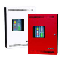
Mircom FR-320 Series Installation And Operation Manual (98 pages)
Pre-Action/Deluge and Agent Release Control Panel
Brand:
Mircom
| Category:
Control Panel
| Size: 9 MB
Table of Contents
Table of Contents
3
Introduction
8
Panel Type
8
Overall Features
8
Conventions
10
Circuits
10
Zone
10
Display Points
10
Wiring Classes
10
System Components
11
Main Pre-Action/Deluge and Agent Release Control Panel
11
Figure 1 FR-320 Series Panel
11
320 Series System Components
12
Table 1 FR-320 Series System Components
12
Additional System Accessories
13
Mechanical Installation
14
Installing the Enclosure
14
Figure 2 Enclosure Dimensions
14
Figure 3 Box Dimensions, Semi-Flush Mounting and Trim Ring
15
Figure 4 Flush Trim Detail
15
BBX-1024DS and BBX-1024DSR Mechanical Installation
16
Figure 5 BBX-1024DS and BBX-1024DSR Installation Instructions and Dimensions
16
Installing the Adder Modules
17
Figure 6 Installation of Adder Modules
17
Cable and Jumper Connections for Main Board, Core Board and Adder Modules
18
Main Pre-Action/Deluge and Agent Release Control Board
18
Figure 7 Main Control Board Cable Connector and Jumper Settings
18
ICAC-306 Input Class a Converter Adder Module
19
Figure 8 ICAC-306 Input Class a Converter Adder Module
19
OCAC-302 Output Class a Converter Adder Module
20
RM-306 Relay Adder Module
20
Figure 9 OCAC-302 Output Class a Converter Adder Module
20
Annunciators
21
Srm-312R/Srm-312W
21
RTI-1 Remote Trouble Indicator
21
Figure 10 RM-306 Six Relay Adder Module
21
Field Wiring
22
Main Board Field Wiring
22
Figure 11 Initiating Device Circuit - Class B Wiring
22
Figure 12 Initiating Device Circuit- Class a Wiring
22
Abort and Manual Release Switch Wiring
23
Figure 13 Abort and Manual Release Switch Class B Wiring
23
Figure 14 Abort and Manual Release Switch Class a Wiring
24
Notification Appliance Circuit Wiring
25
Figure 15 Notification Appliance Circuit - Class B Wiring
25
Figure 16 Notification Appliance Circuit - Class a Wiring
25
Releasing Circuit Wiring
26
Figure 17 Releasing Circuit Wiring
26
Four-Wire Smoke Detector Wiring
27
Relay Adder Module Wiring
27
Figure 18 Four-Wire Smoke Detector Wiring - Class B
27
Figure 19 Relay Per Zone (RM-306) Terminal Connection
27
Releasing Circuit Bypass Switch Wiring
28
Power Supply Connection
28
Figure 20 Release Circuit Bypass Switch Wiring
28
Table 2 Power Supply Rating
28
Figure 21 Power Supply Connection
29
Wiring Tables and Information
30
Table 3 Initiating Device Circuit Wiring Distances
30
Table 4 Notification Appliance Circuit Wiring Distances
30
Releasing Circuits
31
Annunciators
31
Four-Wire Smoke Power (Regulated)
31
Supervised Auxiliary Power (Regulated)
31
Unfiltered Supply (Full Wave Rectified)
31
Table 5 Releasing Circuits Wiring Table
31
Table 6 RS-485 Wiring to Annunciators and Other Devices
31
System Checkout
32
Before Turning the Power "ON
32
Power-Up Procedure
33
Troubleshooting
33
Table 7 Troubleshooting
33
Indicators, Controls and Operations
34
Common LED Indicators
34
Figure 22 LED Indicators and Control Buttons
34
Menu Buttons
36
Switches and Common Indicators
36
Circuit (Zone) Disconnect Buttons (Bypass Switches)
37
Common Controls
37
Common Relays
38
Table 8 Common Relays
38
Circuit Types
39
Evacuation Codes
41
Figure 23 Evacuation and Alert Codes
41
Configuration
42
Table 9 Settings Permitted in CAN/ULCS527
42
Table 10 Settings Permitted in UL864
43
Using the CFG-300 Tool
44
Figure 24 FR-320 Configuration
44
Entering the Passcode
45
How to Use the Keypad to Program the FR-320
45
Table 11 Access Levels
45
Command Menu
46
Figure 25 Command Menu
46
Panel Config (Command-Menu)
47
Set Time (Command-Menu)
52
Set Password (Command-Menu)
54
View Event Log (Command-Menu)
54
Print Event Log
55
Figure 26 Event Log
55
Figure 27 Connect the Computer to the P7 Connector on the Main FR-320 Board
55
Figure 28 Tera Term New Connection
56
Figure 29 Tera Term Serial Port Setup
56
Figure 30 Example Event Log Printout
57
Clear Event Log (Command-Menu)
58
Exit (Command-Menu)
58
Operating the Panel
59
Panel Operation During Various Hazard States
59
General Panel Operation
60
Figure 31 1 Release Timer Active
60
Figure 32 2 Release Timers Active
60
Pre-Programmed Modes
62
Mode 1: Agent Release, Single Hazard, Cross-Zoned, Combined Release
62
Mode 2: Agent Release, Single Hazard, Not Cross-Zoned, Combined Release
64
Mode 3: Agent Release, Dual Hazard, Cross-Zoned, Split Release
66
Mode 4: Agent Release, Dual Hazard, Not Cross-Zoned, Split Release
68
Mode 5: Pre-Action/Deluge, Single Hazard, Cross-Zoned, Combined Release
70
Mode 6: Pre-Action/Deluge, Single Hazard, Not Cross-Zoned, Combined Release
71
Mode 7: Pre-Action/Deluge, Dual Hazard, Cross-Zoned, Split Release
72
Mode 8: Pre-Action/Deluge, Dual Hazard, Not Cross-Zoned, Split Release
74
Mode 9: Agent Release, Single Hazard, Cross-Zoned, NYC Abort
76
Mode 10: Agent Release, Single Hazard, Not Cross-Zoned, Combined Release
78
Mode 11: Agent Release, Single Hazard, Cross-Zoned, Combined Release
80
Mode 12: Pre-Action/Deluge, Single Hazard, Cross-Zoned, Combined Release
82
Mode 13: Pre-Action/Deluge, Single Hazard, Not Cross-Zoned, Combined Release
84
Mode 14: Pre-Action/Deluge, Single Hazard, Not Cross-Zoned, Combined Release
85
Appendix A: Compatible Solenoids
87
Appendix B: Compatible Synchronized Modules and Horn/Strobes (UL/ULC)
88
Compatible Bells
89
Appendix C: Specifications
90
Table 12 FR-320 Series Specifications
90
Table 13 FR-320 Series System Modules and Annunciators
91
Appendix D: Power Supply and Battery Calculations
93
Warranty and Warning Information
94
Advertisement
Related Products
MirCom FA-300 Series
Mircom FA-262
Mircom FA-300-6LDW
Mircom FX-2003-12XTDS
Mircom FX-2003-6DS-16LED
Mircom FX-2017-12ADS
Mircom FA-300-6DDR-CG
Mircom FX-2200 Series
Mircom FA-201
Mircom FA-106
Mircom Categories
Control Panel
Intercom System
Fire Alarms
Security System
Controller
More Mircom Manuals
Login
Sign In
OR
Sign in with Facebook
Sign in with Google
Upload manual
Upload from disk
Upload from URL