
Related Manuals for Mircom FR-320 Series


Summary of Contents for Mircom FR-320 Series
- Page 1 FR-320 Series Pre-Action/Deluge and Agent Release Control Panel LT-951 Rev. 12.1 Installation and Operation Manual Jan. 2017...
-
Page 3: Table Of Contents
Table of Contents FCC Notice 1.0.1 Notice for all FR-320 Series Built-in UDACTs Sold in the U.S.A........1.0.2 FCC Notice ........................Introduction Panel Type ........................2.1.1 Deluge sprinkler system ....................2.1.2 Pre-action sprinkler system .................... 2.1.3 Agent release system .................... - Page 4 Table of Contents Cable and Jumper Connections for Main Board, Core Board and Adder Modules Main Pre-Action/Deluge and Agent Release Control Board .......... 6.1.1 Connectors and Jumpers on the Main Fire Alarm Board ..........6.1.2 Connectors and Jumpers on the Core Board ..............ICAC-306 Input Class-A Converter Adder Module ............
- Page 5 Table of Contents 9.1.5 Remote Trouble ......................9.1.6 Ground Fault ........................9.1.7 CPU Fail ......................... 9.1.8 Abort ..........................9.1.9 Released ........................9.1.10 System Reset ......................... 9.1.11 Signal Silence ........................ 9.1.12 Auxiliary Disconnect ....................... 9.1.13 Lamp Test ........................9.1.14 ALM/SUP/TBL/BLDG AUDIBLE SIL (Buzzer Silence) ........... 9.1.15 Pre Release ........................
- Page 6 Table of Contents 10.2 Entering the Passcode ....................10.3 How to Use the Keypad to Program the FR-320 ............10.4 Command Menu ......................10.5 1. Panel Config (Command-Menu) ................10.5.1 Command Menu-->Panel Config-->Choose a mode ............10.5.2 Command Menu-->Panel Config-->Hazard Config ............10.6 2.
- Page 7 Table of Contents 12.3.2 Hazard Configuration ..................... 12.3.3 NAC Configuration ......................12.3.4 How the Panel Works in Mode 3 ..................12.4 Mode 4: Agent Release, Dual Hazard, Not Cross-zoned, Split Release ....... 12.4.1 Zone Configuration ......................12.4.2 Hazard Configuration ..................... 12.4.3 NAC Configuration ......................
- Page 8 Table of Contents 12.12.2 NAC Configuration ......................12.12.3 How the Panel Works in Mode 12 .................. 12.13 Mode 13: Pre-action/deluge, Single Hazard, Not Cross Zoned, Combined Release ..12.13.1 Zone Configuration ......................12.13.2 Hazard Configuration ..................... 12.13.3 NAC Configuration ......................12.13.4 How the Panel Works in Mode 13 ..................
- Page 9 List of Figures Figure 1 FR-320 Panel ......................... Figure 2 Box dimensions, semi-flush mounting and trim ring ............Figure 3 Flush Trim Detail ......................Figure 4 BBX-1024DS and BBX-1024DSR Installation Instructions and Dimensions ....Figure 5 Installation of Adder Modules ..................Figure 6 Main Control Board cable connector and jumper settings ..........
- Page 10 Troubleshooting ......................Table 6 Relay Types ........................Table 7 Settings permitted in CAN/ULCS527 ................Table 8 Settings permitted in UL864 ................... Table 9 Access Levels ........................ Table 10 FR-320 Series Specifications ..................Table 11 FR-320 System Modules and Annunciators ..............
-
Page 11: Fcc Notice
FCC Notice 1.0.1 Notice for all FR-320 Series Built-in UDACTs Sold in the U.S.A. Notes: The Ringer Equivalence Number (REN) assigned to each terminal device provides an indication of the maximum number of terminals allowed to be connected to a telephone interface. The termination on an interface may consist of any combination of devices subject only to the requirement that the sum of the Ringer Equivalence Numbers of all the devices does not exceed 5. - Page 12 Communicator, they should be performed by Mircom Technologies Ltd. or an authorized representative of Mircom Technologies Ltd. For information contact Mircom Technologies Ltd. at the address and phone numbers shown on the back page of this document.
-
Page 13: Introduction
Introduction Mircom’s FR-320 Series Pre-Action/Deluge and Agent Release Control Panel performs the function of fire suppression in a wide variety of applications. It is capable of being used in an agent release sprinkler system or in a pre-action or deluge sprinkler system. It can be used in single-hazard or dual-hazard applications with or without cross-zoning. - Page 14 Introduction • Subsequent Alarm, Supervisory, and Trouble operation. • Four wire reset-able smoke power supply. • Relay Contacts for Common Alarm, Common Supervisory, Common Trouble, and Auxiliary Alarm Relay (disconnectable). • RS-485 Interface for RA-1000 Series Remote Multiplex Annunciators and Smart relay Module.
-
Page 15: Conventions
Conventions Circuits Refers to an actual electrical interface for initiating (detection), indicating (signal), and releasing. Zone Is a logical concept for a Fire Alarm Protected Area, and will consist of at least one Circuit. Often the terms Zone and Circuit are used interchangeably, but in this Manual the term Circuit is used. -
Page 16: System Components
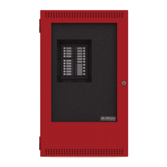
System Components Main Pre-Action/Deluge and Agent Release Control Panel The following models are part of the FR-320 Series: • FR-320 • FR-320-W • FR-320-R • FR-320-DW • FR-320-DR Figure 1 FR-320 Panel All FR-320 Panels have the following features: •... -
Page 17: Relay Modules: Six Relays
SRM-312W Smart Relay Module (12 relays) with white enclosure SRM-312R Smart Relay Module (12 relays) with red enclosure Advanced Life Safety Solutions FR-320 SERIES REMOTE RELAY Input Class A Converter: Six Circuits Model Description Input Class A converter Module (six ICAC-306 circuits). -
Page 18: Output Class A Converter: Two Circuits
System Components Output Class A Converter: Two Circuits Model Description Output Class A converter module (two OCAC-302 circuits) RAM-216 Ancillary Annunciator Model Description A.C. COMMON SIGNAL TROUBLE SILEBCE BUZZER SIGNAL SILENCE SILENCE RAM-216 16 Zone ancillary annunciator SWITCH ENABLE LAMP SYSTEM TEST RESET... -
Page 19: Mechanical Installation
National Electrical Code, ANSI/NFPA 70, and the National Fire Alarm Code ANSI/NFPA 72. Installing the Enclosure Install the FR-320 Series panel enclosure as shown below. Mount enclosure surface mount using the four mounting holes with the provided screws. 11"... -
Page 20: Bbx-1024Ds And Bbx-1024Dsr Mechanical Installation
Mechanical Installation Figure 3 shows a cross-section of the semi-flush mounted backbox and the trim ring. Make sure to allow a minimum depth of 1” above the wall surface for proper door opening. TRIM RING WALL MIN 1” WOOD OR METAL STUD BACKBOX Figure 3... -
Page 21: Figure 4 Bbx-1024Ds And Bbx-1024Dsr Installation Instructions And Dimensions
Mechanical Installation External Dimensions Mounting Dimensions 12.0 " 14.5 " 4.2 " 23.5 " 26.0 " Top View Side View 2.1 " 1.7 " 1.3 " 1.3 " 6.0 " 2.0 " 9.5 " Figure 4 BBX-1024DS and BBX-1024DSR Installation Instructions and Dimensions... -
Page 22: Installing The Adder Modules
Mechanical Installation Installing the Adder Modules The FR-320 Series panel comes pre-assembled with all components and boards except for adder modules. Module installation locations are shown below. Refer to Figure 6 on the next page for Jumper or DIP Switch settings and see 7.8 Wiring Tables and Information on page 35 for wiring specifications. -
Page 23: Cable And Jumper Connections For Main Board, Core Board And Adder Modules
Cable and Jumper Connections for Main Board, Core Board and Adder Modules Main Pre-Action/Deluge and Agent Release Control Board JW4 -Factory Use Only Always Short JW5- Factory Use Only Always Open Main Board Core Board For front panel programming use CFG -300 configuration tool not UL-864 or ULC-S527 listed. -
Page 24: Connectors And Jumpers On The Main Fire Alarm Board
Cable and Jumper Connections for Main Board, Core Board and Adder Modules 6.1.1 Connectors and Jumpers on the Main Fire Alarm Board Remove this jumper if PR-300 is connected. Cable from connector P1 of the RM-306 Relay Adder Module connects here. Otherwise not used. -
Page 25: Ocac-302 Output Class-A Converter Adder Module
Cable and Jumper Connections for Main Board, Core Board and Adder Modules OCAC-302 Output Class-A Converter Adder Module mounting hole for #6-32 screws OCAC-302 mounting hole for #6-32 screws Figure 8 OCAC-302 Output Class-A Converter Adder Module Indicating circuits must be wired from the OCAC-302 to the main Fire Alarm board. For example indicating circuit 1 positive (red wire) and negative (black wire) is wired from the Class A converter module to the positive and negative terminals of Indicating circuit 1 on the Main Fire Alarm board. -
Page 26: Jumpers
Cable and Jumper Connections for Main Board, Core Board and Adder Modules 6.4.1 RM-306 Jumpers Cable from RM-306 Relay Adder Module connects to P4 on Main Fire Alarm Board. 6.4.2 RM-306 Correlations The correlation of the relays are fixed and is as follows: Relay1 Relay2 Relay3... -
Page 27: Field Wiring
Field Wiring Table 1 Settings permitted in CAN/ULCS527 NOTICE TO USERS, INSTALLERS, AUTHORITIES HAVING JURISDICTION, AND OTHER INVOLVED PARTIES This product incorporates field-programmable software. In order for the product to comply with the requirements in CAN/ULCS527, Standard for Control Units for Fire Alarm Systems, certain programming features or options must be limited to specific values or not used at all as indicated below. -
Page 28: Abort And Manual Release Switch Wiring
Field Wiring ICAC-306 DCAC-306 CLASS A CONVERTER MODULE STYLE D WIRING FIRE ALARM MAIN BOARD INITIATING CIRCUIT - 1 ALARM ZONE INITIATING CIRCUIT #1 INITIATING STYLE D CIRCUIT #2 WIRING INITIATING CIRCUIT - 2 4 MORE INITIATING SUPERVISORY CIRCUITS NOT SHOWN ZONE PHOTO ION SMOKE... -
Page 29: Figure 14 Abort And Manual Release Switch Class A Or Style D Wiring
Field Wiring Abort and Manual Release switches on separate circuits ICAC-306 CLASS A FIRE ALARM MAIN BOARD CONVERTER MODULE INITIATING CIRCUIT #5 INITIATING CIRCUIT #6 Manual Release switches on separate circuits ICAC-306 CLASS A CONVERTER FIRE ALARM MAIN BOARD MODULE INITIATING CIRCUIT #5 INITIATING... -
Page 30: Indicating Circuit Wiring
Field Wiring Indicating Circuit Wiring The FR-320 Series Fire Alarm supports Class B or Style Y and Class A Style Z wiring for its indicating circuits. Each circuit is supervised by a 3.9KΩ EOL resistor or active EOL module. Each indicating circuit provides up to 1.7 A, 5 A maximum total if no auxiliaries are used. -
Page 31: Releasing Circuit Wiring
Field Wiring 7.3.1 Releasing Circuit Wiring Wiring for the releasing circuit is shown in Figure 17 below. SIG3 and SIG4 output circuits are reserved for the releasing circuits. Solenoid EOL module (MP-320R/W) is used to supervise the solenoid coil. If the solenoid is already fitted with the directional diode then only the 3.9KΩ EOL resistor is used. -
Page 32: Four-Wire Smoke Detector Wiring
Field Wiring Four-Wire Smoke Detector Wiring FIRE ALARM MAIN BOARD POWER RESETTABLE 4-WIRE SMOKE DETECTOR POWER SUPPLY 22VDC, 200mA MAX. CURRENT - 300mA MAX. RIPPLE VOL. 5mV (POWER LIMITED) DETECTION 4-WIRE DETECTION DEVICE END OF LINE RELAY LISTED S3403 MODEL A77-716B TO INITIATING MANUFACTURED BY CIRCUIT... -
Page 33: Polarity Reversal And City Tie Module (Pr-300) Wiring
Field Wiring Polarity Reversal and City Tie Module (PR-300) Wiring Wire PR-300 Polarity Reversal and City Tie Module (if used) as shown in Figure 21 below. See 17.0 Appendix E: Specifications on page 101 for module specifications. Power Limited cable type FPL, FPLR or FPLP must be used. -
Page 34: Power Supply Connection
Field Wiring 7.7.1 Power Supply Connection The power supply is part of the Main Chassis. The ratings are: Table 2 Power Supply Ratings Type Rating Electrical Input rating 120 VAC 60Hz 1.7A /240 VAC 50 Hz 0.85 A, 10A slow blow fuse on secondary of transformer Power supply total current 6.5A AC maximum @ secondary of transformer... -
Page 35: Wiring Tables And Information
Field Wiring Wiring Tables and Information Table 3 Initiating Circuit Wiring Distances WIRE GAUGE MAXIMUM WIRING RUN TO LAST DEVICE FEET METERS 2990 4760 1450 7560 2300 12000 3600 19000 5800 30400 9200 Notes: For Class A the maximum wiring run to the last device is divided by two. Maximum loop resistance should not exceed 100 ohms. -
Page 36: Supervised Auxiliary Power (Regulated)
Field Wiring 7.10 Supervised Auxiliary Power (regulated) Supervised auxiliary power is used to power the remote annunciators and smart relay modules. This filtered circuit is supervised therefore a short will disconnect the power and the common trouble is active. The power is reconnected after the 'RESET' key is pressed. See 17.0 Appendix E: Specifications on page 101 for supply rating. -
Page 37: System Checkout
System Checkout Before turning the power “ON” To prevent sparking, do not connect the batteries. Connect the batteries after powering the system from the main AC supply. 1. Check that all modules are installed in the proper location with the proper connections. 2. -
Page 38: Troubleshooting
System Checkout Troubleshooting Table 5 Troubleshooting Symptoms Possible Cause To correct the fault, check for open wiring on that particular circuit loop or if the Circuit Disconnect Button is active. Notes: (1) Bypassing a detection circuit or signal circuit will Circuit Trouble cause a system trouble (off-normal status);... -
Page 39: Indicators, Controls And Operations
Trouble Flash (Trouble) - 20 flashes per minute, 50% duty cycle Note: Each display is supplied with laser printer printable paper labels for sliding into the plastic label template on the panel. For the Main Display, the paper label is Mircom# NP-2056. This includes English and French versions. -
Page 40: Common Led Indicators
Indicators, Controls and Operations Common LED Indicators 9.1.1 AC On The AC ON led is on steady green while the main AC power is within acceptable levels. It is turned off when the level falls below the power-fail threshold. 9.1.2 Common Alarm The common alarm led is illuminated steady red as a result of any active alarm present in the system. -
Page 41: Alm/Sup/Tbl/Bldg Audible Sil (Buzzer Silence)
To return to previous menu in the configuration or command mode. Button Switches and Common Indicators The FR-320 Series panel is a six-zone panel with four output circuits. The circuits are arranged in the following configuration: Zone 1 Input circuit... -
Page 42: Out1 And Out2 (Nac Circuits)
Indicators, Controls and Operations 9.3.3 Out1 and Out2 (NAC circuits) • Trouble LED (amber)turns on at slow flash rate when in trouble or bypassed 9.3.4 Out3 and Out4 (Releasing circuits) • Trouble LED (amber)turns on steady when the circuit is bypassed turns on at slow flash rate when in trouble 9.3.5 Input Circuits Bypass Switch... -
Page 43: Lamp Test Button
Indicators, Controls and Operations again de-activates this function and the system will go back to normal. 9.4.4 Lamp Test Button Activation of the Lamp Test button causes all front panel Indicators to steadily illuminate and turns the buzzer ON steady. If Lamp Test is active for more than 10 seconds, Common Trouble is activated. -
Page 44: Common Relays
Indicators, Controls and Operations Common Relays Table 6 Relay Types Relay Type Single Hazard Dual Hazard Trouble Relay Trouble Trouble Supervisory Relay Supervisory Supervisory Alarm Relay Alarm Hazard1 (Alarm) Aux Alarm Relay Alarm (Silence-able) Hazard2 (Alarm) Note: Some troubles are latching once they are detected they remain active until system reset. -
Page 45: Latching Supervisory (For Supervisory Devices)
Indicators, Controls and Operations 9.7.5 Latching Supervisory (For Supervisory Devices) Activation on these circuits will cause the Circuit Status LED and the amber Common Supervisory LED to illuminate. The buzzer will sound at fast rate. If the circuit activation is removed, the Supervisory condition will NOT clear. -
Page 46: Evacuation Codes
Indicators, Controls and Operations Evacuation codes Continuous On 100% of the time Temporal Code 3 of 0.5 second on, 0.5 second off then, 1.5 second pause 20 BPM 1.5 seconds on, 1.5 seconds off 60 BPM 0.5 second on, 0.5 second off 120 BPM 0.25 second on, 0.25 second off CONTINUOUS... -
Page 47: Configuration
Modes 1, 2, 5, 6, 7, 8, release on same circuit 10, 11, 12, 13, 14 9, 10, 11, 12, 13, 14 (unsupervised) Configure the FR-320 Series Panels using the CFG-300 LCD Tool (see further documentation packaged with CFG-300 for configuration information). -
Page 48: Using The Cfg-300 Tool
Configuration 10.1 Using the CFG-300 Tool Connect the CFG-300 to the panel, then press (Menu button). The CFG-300 LCD display will display the Main Menu. The function of different buttons on the front panel display is shown in Figure 25 below. This label removed from this location... -
Page 49: How To Use The Keypad To Program The
Configuration Enter passcode: When the user presses “MENU” and enters the password, they should enter the password of the level intended. If the user is in a lower level of access, attempts to operate functions requiring a higher level of access will be refused. The three levels of access are defined in Table 9. -
Page 50: Command Menu
Configuration 10.4 Command Menu The main command menu is shown in Figure 26. The first line of the LCD will always show “-Command Menu-“, and the second line scrolls through different selections. Use the “UP” and “DOWN” keys to scroll through the menu, and press the key to make a selection. -
Page 51: Panel Config (Command-Menu)
Configuration 10.5 1. Panel Config (Command-Menu) The following is a detailed description of the FR-320 configuration menu. Note: Refer to 10.3 How to Use the Keypad to Program the FR-320 on page 49 for detailed instructions on making menu selections. -P anel C o nfi g- 1. -
Page 52: Command Menu-->Panel Config-->Hazard Config
Configuration 10.5.2 Command Menu-->Panel Config-->Hazard Config -Hazard P aram . - 1. R el ease ti m er 2. Abo rt D el ay 3. Manu al R l s D el ay 4. S o ak ti m er Note: Refer to 10.3 How to Use the Keypad to Program the FR-320 on page 49 for detailed instructions on making menu selections. - Page 53 Configuration Command Menu-->Panel Config--> Hazard Config Use this function to set the time delay 0->Default 3. Man. Rls Delay of activation of corresponding releasing circuit(s) after activation of Available options: the manual release switch. M a n . R ls D e la y (s e c): 0, 5, 10, 15, 20, 25, 30 Value: 0 to 30 seconds in five-second seconds...
- Page 54 Configuration Command Menu-->Panel Config-->Features 1. Manual Sig. Silence Use this function to enable or [X] ENABLE ->Default disable the Signal Silence Man. S i g. S i l. [ ] DISABLE operation on the panel. [X ] EN AB LE Command Menu-->Panel Config-->Features By default all the initiating circuits 2.
- Page 55 Configuration Command Menu-->Panel Config-->Features 8. Alarm Xmit-Sil. Use this function to allow the [ ] ENABLE alarm transmit and auxiliary alarm Al m Xm i t- S i l. relay to reset on the Signal Silence [X] DISABLE->Default rather than the Reset switch. [X ] D I S AB LE Command Menu-->Panel Config-->Features 9.
-
Page 56: Set Time (Command-Menu)
Configuration Command Menu-->Panel Config-->Features 16. Sig-Sil NAC Use this function to set which NAC [X] NAC-1->Default circuits are silenceable or non- S i l enc eabl e N AC [X] NAC-2->Default silenceable. [X ] N AC-1 Command Menu/FR-320 Config/Features/ Enable this function if using an 17. - Page 57 Configuration Command Menu/Time Clock 2. Compensation H H : M M W K D Y Y Y Y - M M - D D Default: 0 seconds Use the up down arrow keys to select daily 0 0 : 0 0 M O N 2 0 0 0 - 0 1 - 0 1 (no compensation) compensation value and press ENTER.
-
Page 58: View Event Log (Command-Menu)
Configuration 10.7 4. View Event Log (Command-Menu) The event log looks the same as the normal event queue. Pressing the “INFO” key has the same effect that it does in the event queue. The illustration below provides an example of how the “INFO”... -
Page 59: Clear Event Log (Command-Menu)
Configuration 10.9 6. Clear Event Log (Command-Menu) Note: Refer to 10.3 How to Use the Keypad to Program the FR-320 on page 49 for detailed instructions on making menu selections. -Select Log- 1. Alarm Log 2. General Log 3. All Logs Select the type of log to clear. -
Page 60: Account Info
Configuration Command Menu-->Dialer Config 10.10.1 Account Info -Account Info- 1. Account#1 ID 2. Account#1 Tel 3. Accnt#1 Format 4. Account#2 ID 5. Account#2 Tel 6. Accnt#2 Format Command Menu/Dialer Config/Account Info Use this function to set the Account ID for the monitoring station to which the dialer 1.Account# 1 Identification reports events. -
Page 61: Telephone Line
Configuration Command Menu/Dialer Config/Account Info 5.Account# 2 Telephone Number ACCOUNT#2 Telnum: [ 101 ]->Default Same as Account#1. Command Menu/Dialer Config/Account Info 6.Account# 2 Reporting Format [X] Contact ID-Default ACCOUNT#2 Format: [ ] SIA 300 Baud Same as Account#1. [ ] SIA 110 Baud [X] CONTACT ID Command Menu-->Dialer Config Note:... -
Page 62: Report Options
Configuration Command Menu/Dialer-Config/Telephone Line 3. Line#1 wait for Dial tone Use this function to let the system know whether or not to wait for a dial tone before [X] ENABLE ->Default dialing. Cell phone setup for the dialer Line#1 Wait Dialtone [ ] DISABLE requires that the system not wait for dial tone before dialing. -
Page 63: Time Parameters
Configuration Command Menu/Dialer-Config/Report Options 2.Trouble priority Use this function to set the account priority for reporting trouble. If the [X] Account 1->Default priority is set for account#1 then the Trouble Report Prio: [ ] Account 2 dialer will try account#1 first for reporting. -
Page 64: Dialer Enable/Disable
Configuration Command Menu/Dialer-Config/Time Parameter Use this function to set the test report date for the cell phone setup. If the date is set to 2. Cellular report date 0 ->Default 0, this means there is no test reporting for cell phone or the phone line is a regular line. The cellular report Cellular Report Date Other settings could be anywhere from 01-... -
Page 65: Test Dialer (Command-Menu)
Configuration 10.11 8. Test Dialer (Command-Menu) -Dialer Test- 1. L#1 Manual test 2. L#2 Manual test 3. Reset Dialer L#1 Manual test Press Enter to test Line #1. Press Cancel to exit this menu. For a description of test messages, see Dialer Test Messages below. -
Page 66: Exit (Command-Menu)
Configuration Dialing Receiver Now The dial tone was received and telephone number dialing is in process. No DTMF tone This message indicates that the dialer failed to send a DTMF tone. Waiting for Acktone Waiting for availability of the receiver. The receiver confirms the availability by sending an ack tone. -
Page 67: Operating The Panel
11.0 Operating the Panel 11.1 Panel Operation During Various Hazard States The escalating hazard zone states include Idle, Alert, Alarm and Release. They are defined based on the status of Hazard Area input zone(s), correlated Abort Switch and Manual Release Switch. 11.1.1 Hazard Idle •... -
Page 68: Hazard Release
Operating the Panel 11.1.4 Hazard Release • Panel enters Hazard Release when the Release Timer or Manual Release Timer expires. The correlated releasing circuit is activated. • NAC code for Hazard Release state is steady. 11.2 General Panel Operation • Activation of Manual Release Switch starts the Manual Release Delay Timer. -
Page 69: Pre-Programmed Modes
12.0 Pre-Programmed Modes 12.1 Mode 1: Agent Release, Single Hazard, Cross-zoned, Combined Release Detection Zones Phantom Zones Release Timers Z1+Z2 Z3+Z4 Out1 Signal Steady Out2 Signal Escalating Out3 Rel. Releasing Out4 Rel. Releasing RLS TMR 1 Started RLS Tmr 1 Interrupted RLS Tmr 1 Cancelled RLS Tmr 2 Started RLS Tmr 2 Interrupted... -
Page 70: How The Panel Works In Mode 1
Pre-Programmed Modes • Hazard Alarm: 120 BPM • Hazard Release: Steady • Default NAC code of Supervisory is 20 BPM. 12.1.4 How the Panel Works in Mode 1 • Activation of either Z-1or Z-2 turns NAC-1 on steady. Hazard Area 1 state changes from Idle into Alert. -
Page 71: Mode 2: Agent Release, Single Hazard, Not Cross-Zoned, Combined Release
Pre-Programmed Modes 12.2 Mode 2: Agent Release, Single Hazard, Not Cross-zoned, Combined Release Detection Zones Phantom Zones Release Timers Z1+Z2 Z3+Z4 Out1 Signal Steady Out2 Signal Escalating Out3 Rel. Releasing Out4 Rel. Releasing RLS TMR 1 Started RLS Tmr 1 Interrupted RLS Tmr 1 Cancelled RLS Tmr 2 Started RLS Tmr 2 Interrupted... -
Page 72: How The Panel Works In Mode
Pre-Programmed Modes 12.2.4 How the Panel Works in Mode 2 • Activation of either Z-1 or Z-2 turns NAC-1 on steady. • Activation of either Z-1 or Z-2 changes the Hazard Area 1 state from Idle into Alarm directly. NAC-1 turns on steady. NAC-2 turns on Temporal. Release Timer-1 is started. •... -
Page 73: Mode 3: Agent Release, Dual Hazard, Cross-Zoned, Split Release
Pre-Programmed Modes 12.3 Mode 3: Agent Release, Dual Hazard, Cross-zoned, Split Release Detection Zones Phantom Zones Release Timers AB/MR AB/MR Z1+Z2 Z3+Z4 Out1 Signal Steady Out2 Signal Escalating Out3 Rel. Releasing Out4 Rel. Releasing RLS TMR 1 Started RLS Tmr 1 Interrupted RLS Tmr 1 Cancelled RLS Tmr 2 Started RLS Tmr 2 Interrupted... -
Page 74: How The Panel Works In Mode 3
Pre-Programmed Modes • Hazard Alarm: 120 BPM • Hazard Release: Steady 12.3.4 How the Panel Works in Mode 3 • Activation of either Z-1 or Z-2 changes Hazard Area1 state from Idle into Alert. NAC-1 turns on at Temporal. • Activations of both Z-1 and Z-2 change Hazard Area1 state from Alert into Alarm. -
Page 75: Mode 4: Agent Release, Dual Hazard, Not Cross-Zoned, Split Release
Pre-Programmed Modes 12.4 Mode 4: Agent Release, Dual Hazard, Not Cross-zoned, Split Release Detection Zones Phantom Zones Release Timers AB/MR AB/MR Z1+Z2 Z3+Z4 Out1 Signal Steady Out2 Signal Escalating Out3 Rel. Releasing Out4 Rel. Releasing RLS TMR 1 Started RLS Tmr 1 Interrupted RLS Tmr 1 Cancelled RLS Tmr 2 Started RLS Tmr 2 Interrupted... -
Page 76: How The Panel Works In Mode 4
Pre-Programmed Modes • Hazard Release: Steady 12.4.4 How the Panel Works in Mode 4 • Activation of either Z-1 or Z-2 changes Hazard Area1 state from Idle to Alarm. NAC-1 turns on at Temporal. Release Timer-1 is started. • Upon expiration of Release Timer-1. RAC-1 is activated. NAC-1 turns on Steady. •... -
Page 77: Mode 5: Pre-Action/Deluge, Single Hazard, Cross-Zoned, Combined Release
Pre-Programmed Modes 12.5 Mode 5: Pre-action/Deluge, Single Hazard, Cross-zoned, Combined Release Detection Zones Phantom Zones RT1 Exp Supv Z1+Z2+Z3+Z4 Out1 Signal Steady Out2 Signal Escalating Out3 Rel. Releasing Out4 Rel. Releasing RLS TMR 1 Started RLS Tmr 1 Interrupted RLS Tmr 1 Cancelled 12.5.1 Zone Configuration •... - Page 78 Pre-Programmed Modes • Activations of any two of Z-1, Z-2, Z-3 and Z-4 change Hazard Area 1 state into Alarm. Release Timer-1 is started. NAC-2 turns on at 120 BPM. Upon the expiration of Release Timer 1, both RAC-1 and RAC-2 turn on. NAC-1 and NAC-2 turn on Steady •...
-
Page 79: Mode 6: Pre-Action/Deluge, Single Hazard, Not Cross-Zoned, Combined Release
Pre-Programmed Modes 12.6 Mode 6: Pre-action/Deluge, Single Hazard, Not Cross-zoned, Combined Release Detection Zones Phantom Zones RT1 Exp Supv Z1+Z2+Z3+Z4 Out1 Signal Steady Out2 Signal Escalating Out3 Rel. Releasing Out4 Rel. Releasing RLS TMR 1 Started RLS Tmr 1 Interrupted RLS Tmr 1 Cancelled 12.6.1 Zone Configuration •... -
Page 80: Mode 7: Pre-Action/Deluge, Dual Hazard, Cross-Zoned, Split Release
Pre-Programmed Modes 12.7 Mode 7: Pre-action/Deluge, Dual Hazard, Cross-zoned, Split Release Detection Zones Phantom Zones Release Timers Supv Z1+Z2 Z3+Z4 Out1 Signal Steady Out2 Signal Escalating Out3 Rel. Releasing Out4 Rel. Releasing RLS TMR 1 Started RLS Tmr 1 Interrupted RLS Tmr 1 Cancelled RLS Tmr 2 Started RLS Tmr 2 Interrupted... -
Page 81: How The Panel Works In Mode 7
Pre-Programmed Modes 12.7.4 How the Panel Works in Mode 7 • Activation of either Z-1 or Z-2 changes Hazard Area 1 state into Alert. NAC-1 turns on at Temporal. • Activations of both Z-1 and Z-2 change Hazard Area 1 state into Alarm. Release Timer- 1 is started. -
Page 82: Mode 8: Pre-Action/Deluge, Dual Hazard, Not Cross-Zoned, Split Release
Pre-Programmed Modes 12.8 Mode 8: Pre-action/Deluge, Dual Hazard, Not Cross-zoned, Split Release Detection Zones Phantom Zones Release Timers Supv Z1+Z2 Z3+Z4 Out1 Signal Steady Out2 Signal Escalating Out3 Rel. Releasing Out4 Rel. Releasing RLS TMR 1 Started RLS Tmr 1 Interrupted RLS Tmr 1 Cancelled RLS Tmr 2 Started RLS Tmr 2 Interrupted... -
Page 83: How The Panel Works In Mode 8
Pre-Programmed Modes 12.8.4 How the Panel Works in Mode 8 • Activation of either Z-1 or Z-2 changes Hazard Area 1 state into Alarm. Release Timer 1 is started. NAC-1 turns on at Temporal. Upon the expiration of Release Timer 1, RAC-1 is active. -
Page 84: Mode 9: Agent Release, Single Hazard, Cross-Zoned, Nyc Abort
Pre-Programmed Modes 12.9 Mode 9: Agent Release, Single Hazard, Cross-zoned, NYC abort Detection Zones Phantom Zones Release Timers Supv Z1+Z2 Z3+Z4 Out1 Signal Steady Out2 Signal Escalating Out3 Rel. Releasing Out4 Strobe Steady RLS TMR 1 Started RLS Tmr 1 Interrupted RLS Tmr 1 Cancelled RLS Tmr 2 Started RLS Tmr 2 Interrupted... -
Page 85: How The Panel Works In Mode 9
Pre-Programmed Modes 12.9.4 How the Panel Works in Mode 9 • The activation of either Z-1 or Z-2 turns NAC-1 on steady. • The activations of both Z-1 and Z-2 turn NAC-1 off, turn NAC-2 on at 120BPM, and turn NAC-3 on steady. -
Page 86: Mode 10: Agent Release, Single Hazard, Not Cross-Zoned, Combined Release
Pre-Programmed Modes 12.10 Mode 10: Agent Release, Single Hazard, Not Cross-zoned, Combined Release Detection Zones Phantom Zones Release Timers Supv Z1+Z2 Z3+Z4 Out1 Signal Steady Out2 Signal Escalating Out3 Rel. Releasing Out4 Rel. Releasing RLS TMR 1 Started RLS Tmr 1 Interrupted RLS Tmr 1 Cancelled RLS Tmr 2 Started RLS Tmr 2 Interrupted... -
Page 87: How The Panel Works In Mode 10
Pre-Programmed Modes 12.10.4 How the Panel Works in Mode 10 • Activation of either Z-1 or Z-2 turns NAC-1 on steady. • Activation of either Z-1 or Z-2 turns NAC-2 on at 60BPM. Release Timer-1 is started. • Expiration of Release Timer-1 activates both RAC-1 and RAC-2. NAC-1 and NAC-2 turn on steady. -
Page 88: Mode 11: Agent Release, Single Hazard, Cross-Zoned, Combined Release
Pre-Programmed Modes 12.11 Mode 11: Agent Release, Single Hazard, Cross-zoned, Combined Release Detection Zones Phantom Zones Release Timers Supv Z1+Z2 Z3+Z4 Out1 Signal Steady Out2 Signal Escalating Out3 Rel. Releasing Out4 Rel. Releasing RLS TMR 1 Started RLS Tmr 1 Interrupted RLS Tmr 1 Cancelled RLS Tmr 2 Started RLS Tmr 2 Interrupted... -
Page 89: How The Panel Works In Mode 11
Pre-Programmed Modes 12.11.4 How the Panel Works in Mode 11 • The activation of either Z-1 or Z-2 turns NAC-1 on steady. • The activations of both Z-1 and Z-2 turn NAC-1 off and turn NAC-2 on at 60BPM. Release Timer-1 is started. •... -
Page 90: Mode 12: Pre-Action/Deluge, Single Hazard, Cross Zoned, Combined Release
Pre-Programmed Modes 12.12 Mode 12: Pre-action/Deluge, Single Hazard, Cross Zoned, Combined Release Attention: This mode of operation is not FM approved. Detection Zones Phantom Zones Supv Supv Z1+Z2+Z3 Out1 Signal Steady Out2 Signal Escalating Out3 Rel. Releasing Out4 Rel. Releasing RLS TMR 1 Started RLS Tmr 1 Interrupted RLS Tmr 1 Cancelled... -
Page 91: How The Panel Works In Mode 12
Pre-Programmed Modes 12.12.3 How the Panel Works in Mode 12 • Activation of Z-1, Z-2 or Z-3 changes Hazard Area 1 state from Idle to Alert. NAC-1 turns on steady. NAC-2 sounds Temporal. • Activations of any two of Z-1, Z-2 and Z-3 change Hazard Area 1 state into Alarm. Release Timer-1 is started. -
Page 92: Mode 13: Pre-Action/Deluge, Single Hazard, Not Cross Zoned, Combined Release
Pre-Programmed Modes 12.13 Mode 13: Pre-action/deluge, Single Hazard, Not Cross Zoned, Combined Release Detection Zones Phantom Zones Supv Supv Z1+Z2+Z3 Out1 Signal Steady Out2 Signal Escalating Out3 Rel. Releasing Out4 Rel. Releasing RLS TMR 1 Started RLS Tmr 1 Interrupted RLS Tmr 1 Cancelled 12.13.1 Zone Configuration •... - Page 93 Pre-Programmed Modes • Activation of Z-6 turns NAC-1 and NAC-2 steady. • For the use of the system for pre-action, deluge releasing applications. • Acceptable, Approved solenoids for the FR-320 are listed in Appendix B. • Secondary power supply must provide for minimum of 90 hours of standby operation followed by 10 minutes of releasing and alarm operation.
-
Page 94: Mode 14: Pre-Action/Deluge, Single Hazard, Not Cross Zoned, Combined Release
Pre-Programmed Modes 12.14 Mode 14: Pre-action/deluge, Single Hazard, Not Cross Zoned, Combined Release Attention: This mode of operation is neither FM nor UL approved. Detection Zones Phantom Zones Supv Z1+Z2+Z3 Out1 Signal Steady Out2 Signal Escalating Out3 Rel. Releasing Out4 Rel. -
Page 95: How The Panel Works In Mode 14
Pre-Programmed Modes 12.14.4 How the Panel Works in Mode 14 • Activation of any one among Z-1, Z-2, Z-3 or Z4 changes Hazard Area 1 state into Alarm. Release Timer-1 is started. NAC-1 turns on steady. NAC-2 turns on Temporal if the release timer is non-zero. -
Page 96: Appendix A: Compatible Receivers
13.0 Appendix A: Compatible Receivers The dialers that are built into select models of the FR-320 Series Pre-Action/Deluge Panels are compatible with the following Digital Alarm Communicator Receivers (DACR): DACR Receiver Model Protocols SurGard MLR2 Multi-Line Receiver (ULC, ULI approved) -
Page 97: Appendix B: Reporting
14.0 Appendix B: Reporting 14.1 Ademco Contact-ID 14.1.1 FR-320 Event Codes Event Description Event Family Qualifier Code Group # Contact # Phone Line #1 trouble detected Trouble New event 1 351 Phone Line #2 trouble detected Trouble New event 1 352 Phone Line #1 trouble restored Trouble Restore... -
Page 98: Security Industries Association Sia-Dcs
Appendix B: Reporting 14.2 Security Industries Association SIA-DCS SIA protocol does not define indicating zone troubles, but lists it as Untyped Zone Trouble/ Restore. 14.2.1 FR-320 Event Codes Event Description Event Family Qualifier Event Parameter Code Phone Line #1 trouble detected Trouble New event Phone Line #2 trouble detected... -
Page 99: Appendix C: Compatible Solenoids
15.0 Appendix C: Compatible Solenoids Manufacturer Description ASCO 8210 series T8210A107 24VDC R8210A107 24VDC 8210A107 24VDC AMEREX 17014 Actuator BSCO 510006 Actuator Kidde Fenwal Protection Systems 486500-01 Actuator Parker 73212 Valve Solenoid Parker Skinner Valve Division Cardox 7-061-0006 V5L 72750 Valve Solenoid SIEMENS CPYEC-2-24... -
Page 100: Appendix D: Compatible Synchronized Modules And Horn/Strobes (Ul/Ulc)
Cooper NS-24MCW-FW/-FR Cooper Wheelock DSM-12-24 Wheelock Horn/Strobes Gentex Secutron AVS44-R MRA-HS3-24 Horn/Strobe SpectrAlert System Sensor P1224 MC Horn/Strobe Amseco/Potter Mircom SDM-240 FHS-240-110 Horn/Strobe ZR-MC-R/-W, ST-MC-R-AR, MTH-MC Strobes Faraday Siemens DSC(-W) ZH-MC-R/-W Horn/ Strobes ZH-R/-W Horns 6234 Series Horn/Strobes Faraday Faraday Note: Separate Circuit for Horn &... -
Page 101: Appendix E: Specifications
17.0 Appendix E: Specifications Table 10 FR-320 Series Specifications FR-320 Series Fire Control Panel Chassis General Digital Signal Processor (DSP) based design. Fully configurable using front panel LCD display with Password Access. Indicating (NAC) 2 supervised style Y (Class B) indicating circuits, configured as strobes or Circuits audibles. -
Page 102: Table 11 Fr-320 System Modules And Annunciators
10AH to 26AH Protection 10A on board (F1) slow blow micro fuse Compliance System Model FR-320 Series Control Unit - Fire Alarm, for Releasing services System Type Local Auxiliary (using PR-300), Remote Protected Premises Station (using PR-300 or FR-320-DR/DW). Central Station Protected Premises (using FR-320- DR/DW.) For ULC application also use PR-300 for... - Page 103 Appendix E: Specifications Table 11 FR-320 System Modules and Annunciators (Continued) FR-320 System Modules and Annunciators PR-300 Polarity Reversal and City Tie Module power limited / 24VDC unfiltered / 250mA max /14Ohms trip coil Polarity Reversal power limited / 24VDC open / 12VDC at 3.5mA / 8.5mA max (shorted) Polarity Reversal Supv.
-
Page 104: Appendix F: Power Supply And Battery Calculations
' Use 0.084 for five minutes, 0.168 for 10 minutes and 0.5 for 30 minutes of alarm as a multiplier figure. Using the Mircom MPD-65P 2-wire photoelectric smoke detector. See 14.0 Appendix B: Reporting on page 97 for other compatible smoke detectors. - Page 105 Battery (AH) = ([STANDBY (A) ______ ] x [(24,60 or 90 Hours) ___ ]) + ([ALARM (B) ______ ] x [Alarm in Hr.] _____) = (C) ______AH Total System Current in Alarm State: Must be 5.5 amperes or less for FR-320 Series. Battery Selection: Multiply (C) by 1.20 to derate battery.
-
Page 106: Warranty And Warning Information
In this document the term MGC System refers to all fire alarm, nurse call, and building automation products manufactured by Mircom Group of Companies, Mircom Technologies Ltd., MGC Systems Corp or subsidiaries and affiliates and includes specific systems such as MiCare™, OpenBAS™, and FlexNet™. - Page 107 Warranty and Warning Information disability, inability to reach the device in time, unfamiliarity with the correct operation, or related circumstances. Insufficient Time There may be circumstances when a MGC System will operate as intended, yet the occupants will not be protected from the emergency due to their inability to respond to the warnings in a timely manner.
-
Page 108: Limited Warranty
Warranty Limited Warranty Mircom Technologies Ltd., MGC Systems Corp. and MGC System International Ltd. together with their subsidiaries and affiliates (collectively, MGC) warrants the original purchaser that for a period of three years from the date of manufacture, proprietary manufactured product shall be free of defects in materials and workmanship, under normal use. - Page 109 Warranty and Warning Information be due. Conditions to Void Warranty This warranty applies only to defects in parts and workmanship relating to normal use. It does not cover: • damage incurred in shipping or handling; • damage caused by disaster such as fire, flood, wind, earthquake or lightning; •...
- Page 110 Warranty and Warning Information which MGC has predetermined and which may be revised from time to time, will be charged for each unit repaired. Products which MGC determines not to be repairable will be replaced by the nearest equivalent product available at that time. The current market price of the replacement product will be charged for each replacement unit.
- Page 111 Warranty and Warning Information...
- Page 112 TECHNICAL SUPPORT U.S.A CANADA - Main Office © Mircom 2017 4575 Witmer Industrial Estates 25 Interchange Way North America Printed in Canada Subject to change without prior notice Tel: (888) Mircom5 Niagara Falls, NY 14305 Vaughan, ON L4K 5W3 Tel: (888) 660-4655...
Need help?
Do you have a question about the FR-320 Series and is the answer not in the manual?
Questions and answers