Sign In
Upload
Manuals
Brands
Juniper Manuals
Switch
EX3300
User Manuals: Juniper EX3300 Ethernet Switch
Manuals and User Guides for Juniper EX3300 Ethernet Switch. We have
6
Juniper EX3300 Ethernet Switch manuals available for free PDF download: Hardware Manual, Complete Hardware Manual, Quick Start Manual
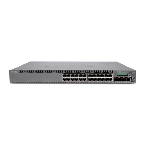
Juniper EX3300 Hardware Manual (354 pages)
Junos OSfor EXSeries EthernetSwitches
Brand:
Juniper
| Category:
Switch
| Size: 3 MB
Table of Contents
Table of Contents
3
About the Documentation
15
Documentation and Release Notes
15
Supported Platforms
15
Using the Examples in this Manual
15
Merging a Full Example
16
Merging a Snippet
16
Documentation Conventions
17
About the Documentation
17
Table 1: Notice Icons
17
Table 2: Text and Syntax Conventions
17
Documentation Feedback
19
Requesting Technical Support
19
Self-Help Online Tools and Resources
19
Opening a Case with JTAC
20
Overview
21
Interfaces Overview
21
Chapter 1 Interfaces Overview
23
Interfaces Overview
23
EX Series Switches Interfaces Overview
23
Network Interfaces
23
Special Interfaces
24
Table 3: Network Interface Types and Purposes
24
Table 4: Special Interface Types and Purposes
24
Understanding Interface Naming Conventions on EX Series Switches
26
Physical Part of an Interface Name
26
Logical Part of an Interface Name
28
Wildcard Characters in Interface Names
28
Understanding Aggregated Ethernet Interfaces and LACP
28
Link Aggregation Group (LAG)
29
Table 5: Maximum Interfaces Per LAG and Maximum Lags Per Switch
29
Link Aggregation Control Protocol (LACP)
30
ECMP Traffic
31
Understanding the Hashing Algorithm
31
IP (Ipv4 and Ipv6)
32
Table 6: Ipv4 and Ipv6 Hashing Fields
33
Mpls
34
Table 7: MPLS Hashing Fields
34
MAC-In-MAC Packet Hashing
35
Layer 2 Header Hashing
35
Table 8: MAC-In-MAC Hashing Fields
35
Table 9: Layer 2 Header Hashing Fields
35
Understanding How Energy Efficient Ethernet Reduces Power Consumption on
36
Interfaces
36
Understanding Local Link Bias
36
Figure 1: Egress Traffic Flow with Local Link Bias
37
Figure 2: Egress Traffic Flow Without Local Link Bias
37
Understanding Layer 3 Subinterfaces
38
Understanding Unicast RPF
39
Unicast RPF for Switches Overview
39
Unicast RPF Implementation
40
Unicast RPF Packet Filtering
40
Bootstrap Protocol (BOOTP) and DHCP Requests
40
Default Route Handling
40
When to Enable Unicast RPF
40
When Not to Enable Unicast RPF
41
Figure 3: Symmetrically Routed Interfaces
41
Limitations of the Unicast RPF Implementation on EX3200, EX4200, and EX4300 Switches
42
Figure 4: Asymmetrically Routed Interfaces
42
Understanding IP Directed Broadcast for EX Series Switches
43
IP Directed Broadcast for EX Series Switches Overview
43
IP Directed Broadcast Implementation for EX Series Switches
43
When to Enable IP Directed Broadcast
44
When Not to Enable IP Directed Broadcast
44
Understanding Interface Ranges on EX Series Switches
44
802.1Q Vlans Overview
46
Configuration
49
Part 2 Configuration
49
Chapter 2 Configuration Tasks
51
Configuring Gigabit Ethernet Interfaces (CLI Procedure)
52
Configuring VLAN Options and Interface Mode
52
Configuring the Link Settings
53
Configuration Tasks
53
Table 10: Factory Default Configuration Link Settings for EX Series Switches
53
Configuring the IP Options
54
Configuring Gigabit Ethernet Interfaces (J-Web Procedure)
55
Table 11: Port Edit Options
57
Table 12: Recommended Cos Settings for Port Roles
60
Port Role Configuration with the J-Web Interface (with CLI References)
61
Table 13: Port Role Configuration Summary
61
Table 14: Recommended Cos Settings for Port Roles
64
Adding a Logical Unit Description to the Configuration
65
Disabling a Physical Interface
65
Example: Disabling a Physical Interface
66
Disabling a Logical Interface
67
Configuring Flow Control
67
Configuring the Interface Address
68
Configuring Interface Ipv4 Addresses
69
Operational Behavior of Interfaces When the same Ipv4 Address Is Assigned to Them
70
Configuring Interface Ipv6 Addresses
71
Configuring the Interface Bandwidth
72
Configuring the Media MTU
73
Media MTU Overview
74
How to Configure the Media MTU
75
Encapsulation Overhead by Encapsulation Type
76
Table 15: Encapsulation Overhead by Encapsulation Type
76
Media MTU Sizes by Interface Type for M5 and M7I Routers with CFEB, M10 and M10I Routers with CFEB, and M20 and M40 Routers
77
Media MTU Sizes by Interface Type for M40E Routers
77
Table 16: Media MTU Sizes by Interface Type for M5 and M7I Routers with CFEB, M10 and M10I Routers with CFEB, and M20 and M40 Routers
77
Table 17: Media MTU Sizes by Interface Type for M40E Routers
77
Media MTU Sizes by Interface Type for M160 Routers
79
Media MTU Sizes by Interface Type for M7I Routers with CFEB-E, M10I Routers with CFEB-E, and M320 and M120 Routers
79
Table 18: Media MTU Sizes by Interface Type for M160 Routers
79
Table 19: Media MTU Sizes by Interface Type for M7I Routers with CFEB-E, M10I Routers with CFEB-E, and M320 and M120 Routers
79
Media MTU Sizes by Interface Type for MX Series Routers
80
Table 20: Media MTU Sizes by Interface Type for MX Series Routers
80
Media MTU Sizes by Interface Type for T320 Routers
81
Media MTU Sizes by Interface Type for T640 Platforms
81
Table 21: Media MTU Sizes by Interface Type for T320 Routers
81
Table 22: Media MTU Sizes by Interface Type for T640 Platforms
81
Media MTU Sizes by Interface Type for J2300 Platforms
82
Media MTU Sizes by Interface Type for J4300 and J6300 Platforms
82
Table 23: Media MTU Sizes by Interface Type for J2300 Platforms
82
Table 24: Media MTU Sizes by Interface Type for J4300 and J6300
82
Media MTU Sizes by Interface Type for J4350 and J6350 Platforms
83
Table 25: Media MTU Sizes by Interface Type for J4350 and J6350
83
Media MTU Sizes by Interface Type for EX Series Switches and ACX Series Routers
85
Media MTU Sizes by Interface Type for PTX Series Packet Transport Routers
85
Setting the Protocol MTU
85
Table 26: Media MTU Sizes by Interface Type for EX Series Switches and ACX
85
Table 27: Media MTU Sizes by Interface Type for PTX Series Packet Transport
85
Interface Ranges
86
Configuring Interface Ranges
87
Expanding Interface Range Member and Member Range Statements
89
Configuration Inheritance for Member Interfaces
90
Member Interfaces Inheriting Configuration from Configuration Groups
91
Interfaces Inheriting Common Configuration
93
Configuring Inheritance Range Priorities
93
Configuration Expansion Where Interface Range Is Used
93
Configuring Accounting for the Physical Interface
94
Applying an Accounting Profile to the Physical Interface
95
Example: Applying an Accounting Profile to the Physical Interface
95
Configuring Accounting for the Logical Interface
96
Applying an Accounting Profile to the Logical Interface
96
Example: Applying an Accounting Profile to the Logical Interface
96
Configuring Ethernet Loopback Capability
97
Configuring Gratuitous ARP
98
Configuring Static ARP Table Entries
99
Example: Configuring Static ARP Table Entries
99
Disabling the Transmission of Redirect Messages on an Interface
100
Configuring Restricted and Unrestricted Proxy ARP
100
Enabling or Disabling SNMP Notifications on Logical Interfaces
101
Configuring Aggregated Ethernet Links (CLI Procedure)
102
Configuring Aggregated Ethernet Interfaces (J-Web Procedure)
103
Table 28: Aggregated Ethernet Interface Options
104
Table 29: VLAN Options
105
Table 30: IP Options
105
Configuring Aggregated Ethernet LACP (CLI Procedure)
106
Configuring LACP Link Protection of Aggregated Ethernet Interfaces
107
Procedure)
108
Configuring LACP Link Protection at the Global Level
108
Configuring LACP Link Protection at the Aggregated Interface Level
108
Configuring Aggregated Ethernet Link Protection
109
Configuring Link Protection for Aggregated Ethernet Interfaces
109
Configuring Primary and Backup Links for Link Aggregated Ethernet
109
Interfaces
109
Reverting Traffic to a Primary Link When Traffic Is Passing through a Backup Link
110
Disabling Link Protection for Aggregated Ethernet Interfaces
110
Configuring Aggregated Ethernet Link Speed
110
Configuring Aggregated Ethernet Minimum Links
112
Configuring Energy Efficient Ethernet on Interfaces (CLI Procedure)
113
Enabling EEE on an EEE-Capable Base-T Copper Ethernet Port
113
Disabling EEE on a Base-T Copper Ethernet Port
113
Configuring Local Link Bias (CLI Procedure)
114
Configuring the Fields in the Algorithm Used to Hash LAG Bundle and ECMP Traffic (CLI Procedure)
114
Configuring the Hashing Algorithm to Use Fields in the Layer 2 Header for Hashing
115
Hashing
115
Hashing
116
Configuring Tagged Aggregated Ethernet Interfaces
116
Configuring a Layer 3 Subinterface (CLI Procedure)
117
Configuring Unicast RPF (CLI Procedure)
117
Disabling Unicast RPF (CLI Procedure)
119
Configuring IP Directed Broadcast (CLI Procedure)
120
Tracing Operations of an Individual Router or Switch Interface
121
Tracing Operations of the Interface Process
121
Configuration Tasks
51
Advertisement
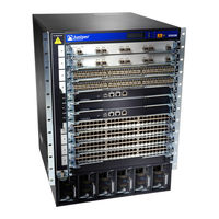
Juniper EX3300 Hardware Manual (272 pages)
Brand:
Juniper
| Category:
Switch
| Size: 3 MB
Table of Contents
Table of Contents
3
List of Tables
13
About the Documentation
17
Documentation and Release Notes
17
Documentation Conventions
17
Supported Platforms
17
Table 1: Notice Icons
18
Table 2: Text and Syntax Conventions
18
About the Documentation
19
Documentation Feedback
19
Opening a Case with JTAC
20
Requesting Technical Support
20
Self-Help Online Tools and Resources
20
Overview
23
Chassis Components and Descriptions
23
Cooling System and Airflow
23
Power Supplies
23
System Overview
23
Chapter 1 System Overview
25
System Overview
25
EX3300 Switches First View
25
EX3300 Switches Hardware Overview
25
EX3300 Switch Models
26
EX3300 Switch Hardware and CLI Terminology Mapping
27
Table 3: EX3300 Switch Models
27
Switches
28
Table 4: CLI Equivalents of Terms Used in Documentation for EX3300
28
Power over Ethernet Plus Ports
26
Uplink Ports
26
Chapter 2 Chassis Components and Descriptions
31
Chassis Physical Specifications for EX3300 Switches
31
Table 5: Physical Specifications of the EX3300 Switch Chassis
31
Front Panel of an EX3300 Switch
32
Figure 1: Front Panel of an EX3300 Switch with 48 Gigabit Ethernet Ports
32
Rear Panel of an EX3300 Switch
33
Figure 2: Front Panel of an EX3300 Switch with 24 Gigabit Ethernet Ports
33
Chassis Components and Descriptions
33
LCD Panel in EX3300 Switches
34
Figure 3: Rear Panel of an EX3300 Switch with an AC Power Supply
34
Figure 4: Rear Panel of an EX3300 Switch with a DC Power Supply
34
Figure 5: LCD Panel
35
LCD Panel Modes
35
LCD Panel Menus
36
Table 6: LCD Panel Menu Options
36
Chassis Status Leds in EX3300 Switches
39
Figure 6: Chassis Status Leds in an EX3300 Switch
39
Table 7: Chassis Status Leds in an EX3300 Switch
39
Management Port Leds in EX3300 Switches
40
Figure 7: Leds on the Management Port on an EX3300 Switch
40
Network Port and Uplink Port Leds in EX3300 Switches
41
Figure 8: Leds on the Network Ports on the Front Panel
41
Figure 9: Leds on the Uplink Ports
41
Table 8: Link/Activity LED on the Management Port on an EX3300 Switch
41
Table 9: Status LED on the Management Port on an EX3300 Switch
41
Table 10: Link/Activity LED on the Network Ports and Uplink Ports in EX3300
42
Table 11: Status LED on the Network Ports in EX3300 Switches
42
Table 12: Status LED on the Uplink Ports in EX3300 Switches
43
Chapter 3 Cooling System and Airflow
45
Cooling System and Airflow in an EX3300 Switch
45
Airflow Direction in EX3300 Switch Models
45
Table 13: Airflow Direction in EX3300 Switch Models
45
Back-To-Front Airflow
46
Figure 10: Front-To-Back Airflow through the EX3300 Switch Chassis
46
Front-To-Back Airflow
46
Figure 11: Back-To-Front Airflow through the EX3300 Switch Chassis
47
Power Supplies
49
Power Supply in EX3300 Switches
49
Table 14: Power Consumed by EX3300 Switches
49
Chapter 4 Power Supplies
49
Chapter 5 Viewing System Information
51
Dashboard for EX Series Switches
51
Graphical Chassis Viewer
52
Table 15: Details of a Virtual Chassis Member Switch
52
Table 16: Status of a Member Switch in a Virtual Chassis
52
System Information Panel
53
Viewing System Information
53
Table 17: System Information
53
Health Status Panel
55
Table 18: Health Status
55
Alarms Panel
57
Capacity Utilization Panel
57
Table 19: Capacity Utilization
57
Chassis Viewer
58
File System Usage
58
Table 20: Chassis Viewer for EX2200 Switches
58
Table 21: Chassis Viewer for EX2200-C and EX2300-C Switches
59
Table 22: Chassis Viewer for EX2300 Switches
60
Table 23: Chassis Viewer for EX3200, EX3300, and EX4200 Switches
61
Table 24: Chassis Viewer for EX3400 and EX4300 Switches
62
Table 25: Chassis Viewer for EX4500 Switches
64
Table 26: Chassis Viewer for EX4550 Switches
65
Table 27: Chassis Viewer for EX6210 Switches
66
Table 28: Chassis Viewer for EX8208 Switches
66
Table 29: Chassis Viewer for EX8216 Switches
68
Table 30: Chassis Viewer for XRE200 External Routing Engines
68
Site Planning, Preparation, and Specifications
71
Preparation Overview
71
Power Specifications and Requirements
71
Transceiver and Cable Specifications
71
Preparation Overview
73
Site Preparation Checklist for EX3300 Switches
73
Table 31: Site Preparation Checklist
73
Chapter 6 Preparation Overview
73
Environmental Requirements and Specifications for EX Series Switches
75
Table 32: EX Series Switch Environmental Tolerances
75
General Site Guidelines
79
Site Electrical Wiring Guidelines
79
Table 33: Site Electrical Wiring Guidelines
79
Chassis Physical Specifications for EX3300 Switches
80
Table 34: Physical Specifications of the EX3300 Switch Chassis
80
Rack Requirements
81
Table 35: Rack Requirements and Specifications
81
Cabinet Requirements
82
Table 36: Cabinet Requirements and Specifications
82
Clearance Requirements for Airflow and Hardware Maintenance for EX3300
83
Figure 12: Clearance Requirements for Airflow and Hardware Maintenance for
83
Switches
83
Figure 13: Front-To-Back Airflow through the EX3300 Switch Chassis
84
Figure 14: Back-To-Front Airflow through the EX3300 Switch Chassis
84
Requirements for Mounting an EX3300 Switch on a Desktop or Wall
83
Chapter 7 Power Specifications and Requirements
87
Power Specifications for EX3300 Switches
87
Switches
87
Table 37: AC Power Supply Electrical Specifications for EX3300 Switches
87
Table 38: DC Power Supply Electrical Specifications for EX3300 Switches
87
AC Power Cord Specifications for EX3300 Switches
88
Table 39: AC Power Cord Specifications
88
Calculating the EX Series Switch Fiber-Optic Cable Power Budget
89
Figure 15: AC Plug Types
89
Calculating the EX Series Switch Fiber-Optic Cable Power Margin
90
Table 40: Estimated Values for Factors Causing Link Loss
91
Chapter 8 Transceiver and Cable Specifications
93
Pluggable Transceivers Supported on EX3300 Switches
93
Table 41: Optical Interface Support and Copper Interface Support for Gigabit Ethernet SFP Transceivers in EX3300 Switches
94
Table 42: Optical Interface Support for SFP+ Gigabit Ethernet Transceivers in
105
Pluggable Transceivers Supported on EX Series Switches
111
SFP+ Direct Attach Copper Cables for EX Series Switches
113
Cable Specifications
113
Figure 16: SFP+ Direct Attach Copper Cables for EX Series Switches
113
Table 43: Software Support for SFP+ Passive Direct Attach Copper Cables for
113
Table 44: SFP+ Direct Attach Copper Cable Specifications
115
Standards Supported by These Cables
117
Management Cable Specifications
117
Understanding EX Series Switches Fiber-Optic Cable Signal Loss, Attenuation
118
And Dispersion
118
Signal Loss in Multimode and Single-Mode Fiber-Optic Cable
118
Table 45: Specifications of Cables to Connect to Management Devices
118
Attenuation and Dispersion in Fiber-Optic Cable
119
Pinout Specifications
121
Console Port Connector Pinout Information
121
Table 46: Console Port Connector Pinout Information
121
Chapter 9 Pinout Specifications
121
USB Port Specifications for an EX Series Switch
122
Port, QSFP+ Port, SFP+ Port, and SFP Port Connector Pinout Information
123
RJ-45 Management Port Connector Pinout Information
123
Table 47: RJ-45 Management Port Connector Pinout Information
123
Table 48: 10/100/1000BASE-T Ethernet Network Port Connector Pinout
124
Table 49: SFP Network Port Connector Pinout Information
124
Table 50: SFP+ Network Port Connector Pinout Information
125
Table 51: QSFP+ Network Port Connector Pinout Information
126
RJ-45 to DB-9 Serial Port Adapter Pinout Information
128
Table 52: RJ-45 to DB-9 Serial Port Adapter Pinout Information
128
Chapter 10 Planning the Virtual Chassis
129
Planning EX3300 Virtual Chassis
129
Understanding EX3300 Virtual Chassis Hardware Configuration
130
Virtual Chassis Cabling Configuration Examples for EX3300 Switches
130
Figure 17: EX3300 Switches Mounted on a Single Rack and Connected in a Ring
131
Figure 18: EX3300 Switches Mounted on a Single Rack and Connected in a Ring
131
Figure 19: EX3300 Switches Mounted on a Single Rack and Connected in a Ring
132
Figure 20: EX3300 Switches Mounted on Adjacent Racks and Connected in a
132
Figure 21: EX3300 Switches Mounted on Adjacent Racks and Connected in a
132
Part 3 Initial Installation and Configuration
133
Unpacking the Switch
135
Unpacking an EX3300 Switch
135
Chapter 11 Unpacking the Switch
135
Parts Inventory (Packing List) for an EX3300 Switch
136
Table 53: Parts List for an EX3300 Switch
136
Registering Products-Mandatory for Validating Slas
137
Chapter 12 Installing the Switch
139
Installing and Connecting an EX3300 Switch
139
Mounting an EX3300 Switch
140
Mounting an EX3300 Switch on a Desk or Other Level Surface
141
Figure 22: Attaching Rubber Feet to a Switch Chassis
141
Mounting an EX3300 Switch on Two Posts in a Rack or Cabinet
142
Figure 23: Attaching the Mounting Bracket Along the Front of the Switch
143
Mounting an EX3300 Switch on Four Posts in a Rack or Cabinet
144
Figure 24: Mounting the Switch on Two Posts in a Rack
144
Figure 25: Attaching the Front-Mounting Bracket to the Side Mounting-Rail
146
Figure 26: Attaching the Side Mounting-Rail to the Switch Chassis
146
Figure 27: Mounting the Switch to the Front Posts in a Rack
147
Figure 28: Sliding the Rear Mounting-Blade into the Side Mounting-Rail
147
Mounting an EX3300 Switch in a Recessed Position in a Rack or Cabinet
148
Mounting an EX3300 Switch on a Wall
148
Figure 29: Attaching Wall-Mount Brackets to a Switch Chassis
149
Figure 30: Measurements for Installing Mounting Screws
150
Figure 31: Mounting the Switch on a Wall
150
Chapter 13 Connecting the Switch to Power
153
Connecting Earth Ground to an EX Series Switch
153
Parts and Tools Required for Connecting an EX Series Switch to Earth Ground
153
Special Instructions to Follow before Connecting Earth Ground to a
154
Table 54: Parts and Tools Required for Connecting an EX Series Switch to Earth Ground
154
Special Instructions to Follow before Connecting Earth Ground to a
155
Connecting Earth Ground to an EX Series Switch
158
Figure 33: Connecting a Grounding Cable to an EX Series Switch
158
Chapter 14 Switch
156
Table 55: Special Instructions to Follow before Connecting Earth Ground to a
156
Figure 32: Connecting the Grounding Lug to a Switch Mounted on Four Posts of
157
Connecting AC Power to an EX3300 Switch
159
Figure 34: Connecting an AC Power Cord Retainer Clip to the AC Power Cord
160
Connecting DC Power to an EX3300 Switch
161
Figure 35: Connecting an AC Power Cord to the AC Power Cord Inlet
161
Figure 36: Securing Ring Lugs to the Terminals on the DC Power Supply
163
Connecting the Switch to the Network
165
Connecting a Device to a Management Console by Using an
165
Connecting a Device to a Network for Out-Of-Band Management
165
Figure 37: RJ-45 Connector on an Ethernet Cable
165
Connector
166
Figure 38: Connecting a Device to a Network for Out-Of-Band Management
166
Figure 39: RJ-45 Connector on an Ethernet Cable
166
Connecting a Fiber-Optic Cable
167
Figure 40: Connecting a Device to a Management Console through a Console
167
Figure 41: Connecting a Device Directly to a Management Console
167
Figure 42: Connecting a Fiber-Optic Cable to an Optical Transceiver Installed in
168
Chapter 15 Performing Initial Configuration
169
EX3300 Switch Default Configuration
169
Connecting and Configuring an EX Series Switch (CLI Procedure)
173
Connecting and Configuring an EX Series Switch (J-Web Procedure)
177
Figure 43: LCD Panel in an EX3200, EX4200, EX4500, EX4550, or EX8200
179
Figure 44: LCD Panel in an EX4300 Switch
179
Configuring the LCD Panel on EX Series Switches (CLI Procedure)
182
Disabling or Enabling Menus and Menu Options on the LCD Panel
182
Configuring a Custom Display Message
183
Installing, Maintaining, and Replacing Components
185
Replacing Transceiver
187
Installing a Transceiver
187
Chapter 16 Replacing Transceiver
187
Figure 45: Installing a Transceiver
189
Removing a Transceiver
189
Figure 46: Removing an SFP, SFP+, XFP, or a QSFP+ Transceiver
191
Maintaining and Replacing Fiber-Optic Cable
193
Connecting a Fiber-Optic Cable
193
Chapter 17 Maintaining and Replacing Fiber-Optic Cable
193
Disconnecting a Fiber-Optic Cable from a Device
194
Figure 47: Connecting a Fiber-Optic Cable to an Optical Transceiver Installed in
194
Maintaining Fiber-Optic Cables
195
Chapter 18 Contactingcustomersupportandreturningthe Chassisor
197
Components
197
Locating the Serial Number on an EX3300 Switch or Component
197
Listing the Switch and Components Details with the CLI
198
Locating the Chassis Serial Number ID Label on an EX3300 Switch
198
Returning an EX3300 Switch or Component for Repair or Replacement
197
Contacting Customer Support to Obtain Return Material Authorization
199
Figure 48: Location of the Serial Number ID Label on EX3300 Switches
199
Packing an EX3300 Switch or Component for Shipping
200
Packing a Switch for Shipping
200
Packing Switch Components for Shipping
201
Troubleshooting
203
Part 5 Troubleshooting
203
Chapter 19 Alarms and Syslog Messages
205
Understanding Alarm Types and Severity Levels on EX Series Switches
205
Table 56: Alarm Terms
205
Chassis Component Alarm Conditions on EX3300 Switches
206
Table 57: Chassis Component Alarm Conditions on EX3300 Switches
207
Checking Active Alarms with the J-Web Interface
213
Monitoring System Log Messages
214
Table 58: Summary of Key Alarm Output Fields
214
Table 59: Filtering System Log Messages
215
Table 60: Viewing System Log Messages
217
Safety and Compliance Information
219
Chapter 20 General Safety Guidelines and Warnings
221
Definitions of Safety Warning Levels
222
Qualified Personnel Warning
224
Warning Statement for Norway and Sweden
225
Chapter 21 Fire Safety Requirements
227
Chapter 22 Installation Safety Guidelines and Warnings
229
Installation Instructions Warning
229
Chassis Lifting Guidelines
230
Restricted Access Warning
230
Ramp Warning
232
Rack-Mounting and Cabinet-Mounting Warnings
232
Wall-Mounting Warning for EX3300 Switches
236
Grounded Equipment Warning
236
Chapter 23 Radiation and Laser Safety Guidelines and Warnings
239
Laser and LED Safety Guidelines and Warnings
239
General Laser Safety Guidelines
239
Class 1 Laser Product Warning
240
Class 1 LED Product Warning
240
Laser Beam Warning
241
Radiation from Open Port Apertures Warning
242
Chapter 24 Maintenance and Operational Safety Warnings
245
Maintenance and Operational Safety Guidelines and Warnings
245
Battery Handling Warning
245
Jewelry Removal Warning
246
Lightning Activity Warning
247
Operating Temperature Warning
248
Product Disposal Warning
249
Chapter 25 Electrical Safety Guidelines and Warnings
251
General Electrical Safety Guidelines and Warnings
251
Action to Take after an Electrical Accident
252
Prevention of Electrostatic Discharge Damage
253
AC Power Electrical Safety Guidelines
254
AC Power Disconnection Warning
255
DC Power Electrical Safety Guidelines for Switches
256
DC Power Disconnection Warning
259
DC Power Grounding Requirements and Warning
260
DC Power Wiring Sequence Warning
261
DC Power Wiring Terminations Warning
263
Multiple Power Supplies Disconnection Warning
264
TN Power Warning
264
Chapter 26 Agency Approvals and Compliance Statements
267
Agency Approvals for EX Series Switches
267
Compliance Statements for EMC Requirements for EX Series Switches
268
Canada
268
European Community
269
Israel
269
Japan
269
FCC Part 15 Statement
270
Korea
270
United States
270
Nonregulatory Environmental Standards
271
Compliance Statements for Acoustic Noise for EX Series Switches
272
Juniper EX3300 Complete Hardware Manual (218 pages)
Brand:
Juniper
| Category:
Switch
| Size: 3 MB
Table of Contents
Table of Contents
3
List of Tables
11
About the Documentation
13
Documentation Conventions
13
Junos os Documentation and Release Notes
13
Table 1: Notice Icons
14
Table 2: Text and Syntax Conventions
14
About the Documentation
15
Documentation Feedback
15
Requesting Technical Support
15
Opening a Case with JTAC
16
Self-Help Online Tools and Resources
16
Chapter 1 EX3300 Switch Overview
17
Chapter 2 Component Descriptions
17
Chapter 3 Component Specifications
17
Switch and Components Overview and Specifications
17
Ex3300 Switch Overview/Ex3300 Switches Hardware Overview
19
EX3300 Switch Overview
19
EX3300 Switches First View
19
EX3300 Switches Hardware Overview
19
EX3300 Switch Models
20
Power over Ethernet Plus Ports
20
Uplink Ports
20
Chassis Physical Specifications for EX3300 Switches
21
Table 3: EX3300 Switch Models
21
Table 4: Physical Specifications of the EX3300 Switch Chassis
21
Front Panel of an EX3300 Switch
22
EX3300 Switch Overview
23
Figure 1: Front Panel of an EX3300 Switch with 48 Gigabit Ethernet Ports
23
Figure 2: Front Panel of an EX3300 Switch with 24 Gigabit Ethernet Ports
23
Rear Panel of an EX3300 Switch
23
EX3300 Switch Hardware and CLI Terminology Mapping
24
Figure 3: Rear Panel of an EX3300 Switch with an AC Power Supply
24
Figure 4: Rear Panel of an EX3300 Switch with a DC Power Supply
24
Table 5: CLI Equivalents of Terms Used in Documentation for EX3300
25
Component Descriptions
27
Figure 5: LCD Panel
27
LCD Panel in EX3300 Switches
27
LCD Panel Modes
28
Component Descriptions
29
LCD Panel Menus
29
Table 6: LCD Panel Menu Options
29
Chassis Status Leds in EX3300 Switches
32
Figure 6: Chassis Status Leds in an EX3300 Switch
32
Table 7: Chassis Status Leds in an EX3300 Switch
32
Figure 7: Leds on the Network Ports on the Front Panel
33
Network Port and Uplink Port Leds in EX3300 Switches
33
Figure 8: Leds on the Uplink Ports
34
Table 8: Link/Activity LED on the Network Ports and Uplink Ports in EX3300
34
Table 9: Status LED on the Network Ports in EX3300 Switches
35
Figure 9: Leds on the Management Port on an EX3300 Switch
36
Management Port Leds in EX3300 Switches
36
Table 10: Status LED on the Uplink Ports in EX3300 Switches
36
Power Supply in EX3300 Switches
37
Table 11: Link/Activity LED on the Management Port on an EX3300 Switch
37
Table 12: Status LED on the Management Port on an EX3300 Switch
37
Table 13: Power Consumed by EX3300 Switches
37
Airflow Direction in EX3300 Switch Models
38
Cooling System and Airflow in an EX3300 Switch
38
Table 14: Airflow Direction in EX3300 Switch Models
38
Back-To-Front Airflow
39
Figure 10: Front-To-Back Airflow through the EX3300 Switch Chassis
39
Front-To-Back Airflow
39
Figure 11: Back-To-Front Airflow through the EX3300 Switch Chassis
40
Component Specifications
41
USB Port Specifications for an EX Series Switch
41
Network Port Connector Pinout Information for an EX3300 Switch
42
Table 15: Network Port Connector Pinout Information for EX3300 Switches
42
Component Specifications
43
Console Port Connector Pinout Information for an EX Series Switch
43
Table 16: EX Series Switches Console Port Connector Pinout Information
43
RJ-45 to DB-9 Serial Port Adapter Pinout Information for a Switch
44
Table 17: RJ-45 to DB-9 Serial Port Adapter Pinout Information
44
Management Port Connector Pinout Information for an EX3300 Switch
45
Table 18: Management Port Connector Pinout Information for EX3300
45
Pluggable Transceivers Supported on EX3300 Switches
46
Table 19: Optical Interface Support and Copper Interface Support for Gigabit Ethernet SFP Transceivers in EX3300 Switches
47
Table 20: Optical Interface Support for SFP+ Gigabit Ethernet Transceivers in
58
SFP+ Direct Attach Cables for EX Series Switches
62
Cable Specifications
63
Figure 12: SFP+ Direct Attach Cables for EX Series Switches
63
Table 21: Software Support for SFP+ Passive Direct Attach Cables for EX Series
64
Table 22: SFP+ Direct Attach Cable Specifications
65
Standards Supported by These Cables
67
Mounting and Clearance Requirements
69
Planning for Switch Installation
69
Chapter 4 Site Preparation
71
Site Preparation Checklist for EX3300 Switches
71
Table 23: Site Preparation Checklist
71
General Site Guidelines
72
Environmental Requirements and Specifications for EX Series Switches
73
Site Electrical Wiring Guidelines
73
Table
73
Table 24: Site Electrical Wiring Guidelines
74
Environmental Requirements and Specifications for EX Series Switches
75
Table 25: EX Series Switch Environmental Tolerances
76
Chapter 5 Mounting and Clearance Requirements
79
Rack Requirements for EX3300 Switches
79
Table 26: Rack Requirements and Specifications for the Switch
79
Cabinet Requirements for EX3300 Switches
80
Requirements for Mounting an EX3300 Switch on a Desktop or Wall
81
Table 27: Cabinet Requirements and Specifications for the Switch
81
Switches
82
Figure 13: Clearance Requirements for Airflow and Hardware Maintenance for EX3300 Switches
82
Figure 14: Front-To-Back Airflow through the EX3300 Switch Chassis
83
Figure 15: Back-To-Front Airflow through the EX3300 Switch Chassis
83
Chapter 6 Cable Specifications
85
Network Cable Specifications for EX3300 Switches
85
Chapter 7 Planning Power Requirements
87
Power Specifications for EX3300 Switches
87
Table 28: AC Power Supply Electrical Specifications for EX3300 Switches
87
Table 29: DC Power Supply Electrical Specifications for EX3300 Switches
87
AC Power Cord Specifications for EX3300 Switches
88
Table 30: AC Power Cord Specifications
88
Figure 16: AC Plug Types
89
Chapter 8 Planning the Virtual Chassis
91
Understanding EX3300 Virtual Chassis Hardware Configuration
91
Planning EX3300 Virtual Chassis
92
Virtual Chassis Cabling Configuration Examples for EX3300 Switches
92
Figure 17: EX3300 Switches Mounted on a Single Rack and Connected in a Ring
93
Figure 18: EX3300 Switches Mounted on a Single Rack and Connected in a Ring
93
Figure 19: EX3300 Switches Mounted on a Single Rack and Connected in a Ring
94
Figure 20: EX3300 Switches Mounted on Adjacent Racks and Connected in a
94
Figure 21: EX3300 Switches Mounted on Adjacent Racks and Connected in a
94
Installing and Connecting the Switch and Switch Components
95
Chapter 9 Installing the Switch
97
Installing and Connecting an EX3300 Switch
97
Installing and Connecting an EX3300 Switch
98
Unpacking an EX3300 Switch
98
Parts Inventory (Packing List) for an EX3300 Switch
99
Table 31: Parts List for an EX3300 Switch
99
Unpacking an EX3300 Switch
99
Mounting an EX3300 Switch
100
Mounting an EX3300 Switch in a Recessed Position in a Rack or Cabinet
100
Mounting an EX3300 Switch on a Desk or Other Level Surface
100
Mounting an EX3300 Switch on a Wall
100
Mounting an EX3300 Switch on Four Posts in a Rack or Cabinet
100
Mounting an EX3300 Switch on Two Posts in a Rack or Cabinet
100
Figure 22: Attaching the Mounting Bracket Along the Front of the Switch
102
Figure 23: Mounting the Switch on Two Posts in a Rack
102
Advertisement
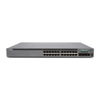
Juniper EX3300 Complete Hardware Manual (202 pages)
Brand:
Juniper
| Category:
Switch
| Size: 3 MB
Table of Contents
Table of Contents
7
About this Topic Collection
17
How to Use this Guide
17
List of EX Series Guides for Junos os Release 11.3
17
Component Descriptions
17
Downloading Software
19
Documentation Symbols Key
20
Documentation Feedback
21
Requesting Technical Support
22
Self-Help Online Tools and Resources
22
Opening a Case with JTAC
22
Switch and Components Overview and Specifications
23
EX3300 Switch Overview
23
EX3300 Switch Overview
25
EX3300 Switches Hardware Overview
25
EX3300 Switches First View
25
Uplink Ports
26
Power over Ethernet Plus Ports
26
EX3300 Switch Models
26
Chassis Physical Specifications for EX3300 Switches
27
EX3300 Switch Overview
27
Table 1: EX3300 Switch Models
27
Table 2: Physical Specifications of the EX3300 Switch Chassis
27
Front Panel of an EX3300 Switch
28
Figure 1: Front Panel of an EX3300 Switch with 48 Gigabit Ethernet Ports
28
Rear Panel of an EX3300 Switch
29
Figure 2: Front Panel of an EX3300 Switch with 24 Gigabit Ethernet Ports
29
EX3300 Switch Hardware and CLI Terminology Mapping
30
Figure 3: Rear Panel of an EX3300 Switch with an AC Power Supply
30
Figure 4: Rear Panel of an EX3300 Switch with a DC Power Supply
30
Table 3: CLI Equivalents of Terms Used in Documentation for EX3300
31
Component Descriptions
33
LCD Panel in EX3300 Switches
33
Figure 5: LCD Panel
33
LCD Panel Modes
34
This Topic Describes
34
LCD Panel Menus
35
Component Descriptions
35
Table 4: LCD Panel Menu Options
35
Chassis Status Leds in EX3300 Switches
38
Figure 6: Chassis Status Leds in an EX3300 Switch
38
Table 5: Chassis Status Leds in an EX3300 Switch
38
Uplink Ports
38
Network Port and Uplink Port Leds in EX3300 Switches
39
Figure 7: Leds on the Network Ports on the Front Panel
39
Figure 8: Leds on the Uplink Ports
39
Table 6: Link/Activity LED on the Network Ports and Uplink Ports in EX3300
40
Table 7: Status LED on the Network Ports and Uplink Ports in EX3300
41
Management Port Leds in EX3300 Switches
42
Figure 9: Leds on the Management Port on an EX3300 Switch
42
Table 8: Link/Activity LED on the Management Port on an EX3300 Switch
42
Table 9: Status LED on the Management Port on an EX3300 Switch
42
Power Supply in EX3300 Switches
43
Table 10: Power Consumed by EX3300 Switches
43
Cooling System and Airflow in an EX3300 Switch
44
Figure 10: Front-To-Back Airflow through the EX3300 Switch Chassis
44
Table 11: Airflow Direction in EX3300 Switch Models
44
Figure 11: Back-To-Front Airflow through the EX3300 Switch Chassis
45
Component Specifications
47
USB Port Specifications for an EX Series Switch
47
Network Port Connector Pinout Information for an EX3300 Switch
48
Table 12: Network Port Connector Pinout Information for EX3300 Switches
48
Console Port Connector Pinout Information for an EX Series Switch
49
Table 13: EX Series Switches Console Port Connector Pinout Information
49
Management Port Connector Pinout Information for an EX3300 Switch
50
Table 14: Management Port Connector Pinout Information for EX3300
50
Optical Interface Support in EX3300 Switches
51
Table 15: Optical Interface Support for Gigabit Ethernet SFP Transceivers
52
Table 16: Optical Interface Support for SFP+ Gigabit Ethernet Transceivers
54
SFP+ Direct Attach Cables for EX Series Switches
57
Cable Specifications
58
Table 17: Software Support for SFP+ Direct Attach Cables Listed by Software
58
Standards Supported by These Cables
59
Table 18: SFP+ Direct Attach Cable Specifications
59
Planning for Switch Installation
61
Mounting and Clearance Requirements
61
Site Preparation
63
Site Preparation Checklist for EX3300 Switches
63
Table 19: Site Preparation Checklist
63
General Site Guidelines
64
Site Electrical Wiring Guidelines
65
Table 20: Site Electrical Wiring Guidelines
66
Environmental Requirements and Specifications for EX Series Switches
67
Table 21: EX Series Switch Environmental Tolerances
67
Mounting and Clearance Requirements
69
Rack Requirements for EX3300 Switches
69
Table 22: Rack Requirements and Specifications for the Switch
69
Cabinet Requirements for EX3300 Switches
70
Table 23: Cabinet Requirements and Specifications for the Switch
71
Requirements for Mounting an EX3300 Switch on a Desktop or Wall
72
Clearance Requirements for Airflow and Hardware Maintenance for EX3300
72
Switches
72
Figure 12: Clearance Requirements for Airflow and Hardware Maintenance for
72
Figure 13: Front-To-Back Airflow through the EX3300 Switch Chassis
73
Figure 14: Back-To-Front Airflow through the EX3300 Switch Chassis
74
Cable Specifications
75
Network Cable Specifications for EX3300 Switches
75
Planning Power Requirements
77
Power Specifications for EX3300 Switches
77
Table 24: AC Power Supply Electrical Specifications for EX3300 Switches
77
Table 25: DC Power Supply Electrical Specifications for EX3300 Switches
77
AC Power Cord Specifications for EX3300 Switches
78
Table 26: AC Power Cord Specifications
78
Figure 15: AC Plug Types
79
Planning the Virtual Chassis
81
Understanding EX3300 Virtual Chassis Hardware Configuration
81
Planning EX3300 Virtual Chassis
82
Virtual Chassis Cabling Configuration Examples for EX3300 Switches
82
Figure 16: EX3300 Switches Mounted on a Single Rack and Connected in a Ring
83
Figure 17: EX3300 Switches Mounted on a Single Rack and Connected in a Ring
83
Figure 18: EX3300 Switches Mounted on a Single Rack and Connected in a Ring
84
Figure 19: EX3300 Switches Mounted on Adjacent Racks and Connected in a
84
Figure 20: EX3300 Switches Mounted on Adjacent Racks and Connected in a
84
Installing and Connecting the Switch and Switch Components
85
Installing the Switch
87
Installing and Connecting an EX3300 Switch
87
Unpacking an EX3300 Switch
88
Parts Inventory (Packing List) for an EX3300 Switch
89
Table 27: Parts List for an EX3300 Switch
89
Mounting an EX3300 Switch
90
Mounting an EX3300 Switch on Two Posts in a Rack or Cabinet
90
Figure 21: Attaching the Mounting Bracket Along the Front of the Switch
92
Figure 22: Mounting the Switch on Two Posts in a Rack
92
Mounting an EX3300 Switch on Four Posts in a Rack or Cabinet
93
Figure 23: Attaching the Front Bracket to the Side-Rail Bracket
94
Figure 24: Attaching the Side-Rail Bracket to the Switch Chassis
94
Figure 25: Mounting the Switch to the Front Posts in a Rack
95
Figure 26: Sliding the Rear Brackets to the Rear of a Four-Post Rack
95
Mounting an EX3300 Switch in a Recessed Position in a Rack or Cabinet
96
Mounting an EX3300 Switch on a Desk or Other Level Surface
96
Mounting an EX3300 Switch on a Wall
97
Figure 27: Attaching Rubber Feet to a Switch Chassis
97
Figure 28: Attaching Wall-Mount Brackets to a Switch Chassis
98
Figure 29: Measurements for Installing Mounting Screws
99
Figure 30: Mounting the Switch on a Wall
100
Installing Switch Components
101
Installing a Transceiver in an EX Series Switch
101
Figure 31: Installing a Transceiver in an EX Series Switch
102
Connecting the Switch
105
Connecting Earth Ground to an EX Series Switch
105
Figure 32: Connecting a Grounding Cable to an EX Series Switch
105
Connecting Earth Ground to an EX2200, EX3200, or EX3300 Switch
106
Connecting Earth Ground to an EX4200 Switch
107
Connecting Earth Ground to an EX4500 Switch
108
Figure 33: Connecting the Grounding Lug to an EX4200 Switch on a Four-Post
108
Connecting Earth Ground to an EX6210 Switch
109
Figure 34: Location of Protective Earthing Terminal on an Ex6210 Switch
110
Connecting Earth Ground to an EX8208 Switch
111
Connecting Earth Ground to an EX8216 Switch
111
Connecting AC Power to an EX3300 Switch
113
Connecting DC Power to an EX3300 Switch
114
Figure 35: Connecting an AC Power Cord Retainer Clip to the AC Power Cord
114
Figure 36: Connecting an AC Power Cord to the AC Power Cord Inlet
114
Juniper EX3300 Hardware Manual (156 pages)
EX Series
Brand:
Juniper
| Category:
Switch
| Size: 2 MB
Table of Contents
Table of Contents
3
About the Documentation
13
Documentation and Release Notes
13
Supported Platforms
13
Documentation Conventions
13
Table 1: Notice Icons
14
Table 2: Text and Syntax Conventions
14
Documentation Feedback
15
About the Documentation
15
Requesting Technical Support
16
Self-Help Online Tools and Resources
16
Opening a Case with JTAC
16
Overview
19
System Overview
19
Chassis Components and Descriptions
19
Power Supplies
19
Chapter 1 System Overview
21
System Overview
21
EX Series Redundant Power System Hardware Overview
22
Switch Models and Configurations Supported by the RPS
22
When a Switch's Power Supply Fails
23
System Overview
23
Table 3: Sample Requirements and RPS Solutions
23
Components of the RPS
24
Understanding How Power Priority Is Determined and Set for Switches Connected to the EX Series Redundant Power System
24
Table 4: Redundant Power System Components
24
Changing the Priority of Switches on an EX Series RPS
25
Default RPS Priority
25
Figure 1: Default Poe Switch Priority Is Determined by Connector Port
25
Figure 2: Switch Priority after CLI Configuration
25
Physical Description of a Redundant Power System
26
Power Supply Side of a Redundant Power System
26
Switch Connector Side of a Redundant Power System
27
Figure 3: Power Supply Side of the RPS
27
Figure 4: Switch Connector Side of the RPS
27
Chapter 2 Chassis Components and Descriptions
29
Chassis Physical Specifications for the EX Series Redundant Power System
29
Leds on an EX Series Redundant Power System
29
Table 5: Physical Specifications of the RPS Chassis
29
Figure 5: Leds on an RPS
30
Table 6: Leds on an RPS
30
Chapter 3 Power Supplies
31
Power Supply Leds in an EX Series Redundant Power System
32
Figure 6: EX-PWR3-930-AC Power Supply in a Redundant Power System
32
Table 7: Power Supply Leds in a Redundant Power System
32
Power Supplies
31
Power Supply in an EX Series Redundant Power System
31
Site Planning, Preparation, and Specifications
33
Preparation Overview
33
Power Specifications and Requirements
33
Chapter 4 Preparation Overview
35
General Site Guidelines
37
Site Electrical Wiring Guidelines
37
Preparation Overview
37
Table 9: Site Electrical Wiring Guidelines
37
Rack Requirements
38
Table 10: Rack Requirements and Specifications
38
Cabinet Requirements
39
Table 11: Cabinet Requirements and Specifications
39
Clearance Requirements for Airflow and Hardware Maintenance for an EX Series Redundant Power System
40
Redundant Power System
40
Preparation Overview
35
Site Preparation Checklist for an EX Series Redundant Power System
35
Figure 7: Clearance Requirements for Airflow and Hardware Maintenance for an
35
Table 8: Site Preparation Checklist
35
Chapter 5 Power Specifications and Requirements
43
Power Specifications for the EX Series Redundant Power System
43
AC Power Cord Specifications for the EX Series Redundant Power System
43
Table 12: AC Power Supply Electrical Specifications for an RPS Power Supply
43
Table 13: AC Power Cord Specifications
44
Power Specifications and Requirements
45
Figure 8: AC Plug Types
45
Chapter 6 Unpacking the RPS
47
Unpacking the RPS
49
Unpacking an EX Series Redundant Power System
49
Parts Inventory (Packing List) for an EX Series Redundant Power System
50
Table 14: Inventory of Components Provided with the RPS
50
Chapter 7 Installing the RPS
51
Mounting the EX Series Redundant Power System
51
Mounting an EX Series Redundant Power System in a Recessed Position in a Rack or Cabinet
52
Mounting an EX Series Redundant Power System on Four Posts in a Rack or Cabinet
52
Figure 9: Attaching the Front Bracket to the Side-Rail Bracket
54
Figure 10: Attaching the Side-Rail Bracket to the Chassis
54
Figure 11: Mounting the RPS to the Front Posts of a Rack
55
Figure 12: Sliding the Rear Brackets to the Rear of a Four-Post Rack
55
Mounting an EX Series Redundant Power System on Two Posts in a Rack or Cabinet
56
Figure 13: Attaching the Mounting Bracket to the Side Panel of the RPS
57
Figure 14: Mounting the RPS on Two Posts in a Rack
58
Initial Installation and Configuration
47
Installing the RPS
47
Chapter 8 Connecting the RPS
59
Connecting the RPS
61
Connecting the RPS
59
Connecting Power to an EX Series Redundant Power System Power Supply
59
Switch
59
Figure 15: each Power Supply Must be Plugged in
61
Figure 16: RPS Cable
62
Figure 17: Connect the RPS Cable to the Switch
63
Chapter 9 Performing Initial Configuration
65
Using RPS Default Configuration
66
Setting the EX Series RPS Priority for a Switch (CLI)
66
Performing Initial Configuration
65
Rps
65
Chapter 10 Replacing Power Supply
69
Installing, Maintaining, and Replacing Components
69
Replacing Power Supply
71
Installing a Power Supply in the EX Series Redundant Power System
71
Removing a Power Supply from the EX Series RPS
72
Figure 18: Installing a Power Supply in the RPS
72
Figure 19: Removing a Power Supply
74
Routine Maintenance
75
Upgrading Firmware on an EX Series Redundant Power System
75
Determine the Current EX Series RPS Firmware Version
75
Connect the Supplied Cable from the EX Series RPS to the Network
76
Use an Attached Switch's CLI to Upgrade EX Series RPS Firmware
76
Figure 20: Connecting the RJ-45 Cable for a Firmware Upgrade
76
Example: Upgrading EX Series RPS Firmware Using an EX2200 Switch
77
Chapter 11 Routine Maintenance
77
Example: Upgrading EX Series RPS Firmware from an EX3300 Switch
78
Chapter 12 Contactingcustomersupportandreturningthechassisor
79
Components
79
Returning an EX Series RPS or RPS Component for Repair or Replacement
79
Locating the Serial Number on an EX Series Redundant Power System or Redundant Power System Components
80
Cli
80
Locating the Chassis Serial Number ID Label on an EX Series RPS
80
Locating the Serial Number ID Labels on a Power Supply in an EX Series Redundant Power System
80
Contacting Customer Support to Obtain Return Material Authorization
81
Packing an EX Series Redundant Power System or Redundant Power System Components for Shipping
81
Packing an EX Series RPS for Shipping
82
Packing an EX Series RPS Component for Shipping
83
Part 5 Troubleshooting
85
Troubleshooting
85
Alarms and Syslog Messages
85
Chapter 13 Troubleshooting Procedures
87
A Switch Is Not Recognized by the RPS
88
An Error Message Indicates that an RPS Power Supply Is Not Supported
88
The EX Series Redundant Power System Is Not Providing Power Backup to a Connected Switch
88
The Wrong Switches Are Being Backed up
89
Six Switches that Do Not Require Poe Are Not All Being Backed up
89
Troubleshooting Procedures
87
Backup Issues
87
The EX Series RPS Is Not Powering on
87
Troubleshooting
87
Juniper EX3300 Quick Start Manual (9 pages)
Brand:
Juniper
| Category:
Switch
| Size: 0 MB
Table of Contents
Step 1: Begin
1
Mount the EX3300 on Two Posts of a Rack
2
Connect Power to the EX3300
2
Connecting EX3300 to AC Power
3
Connecting EX3300 to DC Power
4
Step 2: up and Running
5
Step 3: Perform Initial Configuration
5
Perform the Initial Configuration
5
Step 3: Keep Going
6
Safety Warnings Summary
7
Power Cable Warning (Japanese)
7
Contacting Juniper Networks
8
Advertisement
Related Products
Juniper EX3300-24T
Juniper EX3300-24P
Juniper EX3300-24T-DC
Juniper EX3300-48T
Juniper EX3300-48T-BF
Juniper EX3300-48P
Juniper EX 3200 24T
Juniper EX 3200 48P
Juniper EX3200-24P
Juniper EX3200-48P
Juniper Categories
Network Router
Switch
Gateway
Software
Network Hardware
More Juniper Manuals
Login
Sign In
OR
Sign in with Facebook
Sign in with Google
Upload manual
Upload from disk
Upload from URL