Sign In
Upload
Manuals
Brands
JCM GLOBAL Manuals
Bank Note Validator
DBV Series
JCM GLOBAL DBV Series Manuals
Manuals and User Guides for JCM GLOBAL DBV Series. We have
2
JCM GLOBAL DBV Series manuals available for free PDF download: Operation And Maintenance Manual, Integration Manual
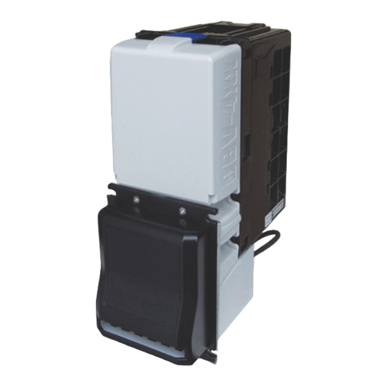
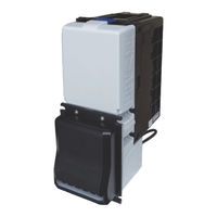
JCM GLOBAL DBV Series Operation And Maintenance Manual (102 pages)
Banknote acceptor
Brand:
JCM GLOBAL
| Category:
Industrial Equipment
| Size: 8.92 MB
Table of Contents
Table of Contents
3
DBV™ Series
13
DBV-500 Banknote Acceptor
13
General Information
13
DBV-500 Unit
13
Product Descriptions
14
Model Descriptions
14
Type Descriptions
14
Software Descriptions
14
Precautions
15
User Cautions
15
Installation Cautions
15
Mounting, Dismounting & Transportation
15
Placing Foreign Objects into the Unit
15
Preventive Maintenance
15
Banknote Fitness Requirements
16
Primary Features
16
Component Names
17
Specifications
18
Technical Specifications
18
Environmental Specifications
19
Electrical Specifications
19
Structural Specifications
19
Unit Dimensions
20
Entire Unit Outside Dimensions
20
Bezel Type a Dimensions
21
Bezel Type B Dimensions
21
DBV-500 Installation/Maintenance Space Requirements
22
Technical Contact Information
23
Americas
23
JCM American
23
Europe, Middle East, Africa & Russia
23
JCM Europe Gmbh
23
UK & Ireland
23
JCM Europe (UK Office)
23
Asia and Oceania
23
Japan Cash Machine Co., Ltd. (Hq)
23
Installation
25
Installation Procedure
25
Grounding
25
Unit Installation
25
Standard Installation
25
Unit Installation with Panel Bracket
26
Lock Dimension Reference
26
Lock Installation
26
Plastic Latch Installation
26
Metal Lock Installation
27
Frame Lock Installation
27
DIP Switch Configurations
28
DIP Switch Block 1
28
DIP Switch Block 2
28
Connector Pin Assignments
29
Photo-Coupler Isolation Connector Pin Assignments
29
RS232C Connector Pin Assignments
30
TTL Connector Pin Assignments
31
USB Connector Pin Assignments
32
ID-044 Connector Pin Assignments
33
Option Connector Pin Assignments
34
Preventive Maintenance
35
Retrieving Banknotes
35
Clearing a Banknote Jam
35
Cleaning Procedure
36
Sensor and Roller Cleaning Procedure
36
Sensor and Roller Locations
37
Operational Flowchart
45
Figure 2-35 DBV-500 Operational Flowchart (Initializing)
45
Operational Flowchart (Continued 1)
46
Operational Flowchart (Continued 2)
47
Communications
49
Americas
49
JCM American
49
Europe, Middle East, Africa & Russia
49
JCM Europe Gmbh
49
UK & Ireland
49
JCM Europe (UK Office)
49
Asia and Oceania
49
Japan Cash Machine Co., Ltd. (Hq)
49
Disassembly/Reassembly
51
Tool Requirements
51
Main Board Removal
51
Figure 4-1 Cash Box Removal
51
Figure 4-2 Bezel Removal
51
Figure 4-3 Base Plate Removal
51
Side Sensor Board Removal
52
Figure 4-4 CPU Protective Sheet Removal
52
Figure 4-5 Main Board Removal
52
Figure 4-6 Connector Removal
52
Figure 4-7 Side Sensor Board Removal
52
Main Frame/Upper Guide Removal
53
Transport Motor/Stacker Motor Removal
53
Inside Sensor Board Removal
53
Centering Home Sensor Board Removal
53
Figure 4-8 Upper Guide Removal
53
Figure 4-9 Transport Motor/Stacker Motor Removal
53
Figure 4-10 Inside Sensor Board Removal
53
Figure 4-11 Upper Cover Removal
53
Centering Motor Removal
54
Outside Sensor Board Removal
54
Figure 4-12 Connector Removal
54
Figure 4-13 Centering Home Sensor Board Removal
54
Figure 4-14 Centering Motor Removal
54
Figure 4-15 Lower Guide Removal
54
Figure 4-16 Upper Guide 2 Removal
54
Figure 4-17 Upper Guide 1 Removal
55
Figure 4-18 Seal Sponge Removal
55
Wiring Diagrams
57
System Wiring Diagram
57
Figure 5-1 DBV-500 System Wiring Diagram
57
Calibration and Testing
59
Tool Requirement
59
Installation Procedures
59
Application Software Installation
59
Figure 6-1 Tool and Harness Connections
59
Figure 6-2 USB Cable Type Requirement
59
Figure 6-3 Setup.exe File Location
59
Figure 6-4 Installshield Wizard Screen
59
Driver Installation Procedure
60
Figure 6-5 Destination Folder Screen
60
Figure 6-6 Current Settings Confirmation
60
Figure 6-7 Installation Completion Screen
60
JCM Tool Suite Standard Edition Mode
61
Download Procedures
61
Software Program Download
61
Figure 6-10 Normal Mode Selection
61
Figure 6-11 Test Mode Selection
61
Figure 6-12 Normal Upgrade Setting
61
Figure 6-13 Initial Download Setting
61
Figure 6-14 Normal Upgrade Screen
61
Figure 6-15 Initial Download Screen
61
Calibration
62
Figure 6-16 JCM Tool Suite Standard Edition Screen Pull-Down Menu
62
Figure 6-17 Browse Screen Button Location
62
Figure 6-18 DBV-500 Software Program Selection
62
When to Calibrate
63
Placing the KS-091 Reference Paper
63
Figure 6-21 KS-091 Reference Paper
63
Figure 6-22 Placing KS-091 Reference Paper 1
63
Figure 6-23 Placing KS-091 Reference Paper 2
63
Calibration Preparation
64
Sensor Calibration
64
Figure 6-25 DIP SW1 Setting
64
Figure 6-26 Launching JCM Tool Suite Standard Edition Screen
64
Figure 6-27 Sensor Adjustment Selection
64
Figure 6-30 Non-Paper Calibration Screen
64
Figure 6-31 Non-Paper Calibration Completion
65
Figure 6-32 Placing Reference Paper Message
65
Figure 6-33 Reference Paper Calibration
65
Figure 6-34 Removing Reference Paper Message
65
Figure 6-35 Second Non-Paper Calibration
65
Figure 6-36 Serial Number Change Dialogue
65
Serial Number Setting
66
Figure 6-39 Calibration Result
66
Figure 6-40 Serial Number Setting Button
66
Figure 6-41 Set Serial Number Screen
66
Figure 6-42 Serial Number Setting Completion
66
White Level Test
67
Performance Tests
67
Performance Test Using a PC
67
Performance Test Preparation
67
Figure 6-43 White Level Test Button
67
Figure 6-44 White Level Test Start Button
67
Figure 6-45 White Level Test Completion
67
Figure 6-46 DIP SW1 Setting
67
Figure 6-47 JCM Tool Suite Standard Edition Initial Screen
67
Performance Test Items Using a PC
68
Feed Motor Test
68
Figure 6-48 Performance Test Main Screen
68
Figure 6-49 Feed Motor Test Selection
68
Figure 6-50 Feed Motor Test Start Button
68
Figure 6-51 Feed Motor Test Stop Button
68
Stacking Movement Test
69
Sensor Test
69
Figure 6-52 Stacking Movement Test Selection
69
Figure 6-53 Stacking Movement Test Start Button
69
Figure 6-54 Stacking Movement Test Stop Button
69
DIP SW1/SW2 Test
70
Figure 6-55 Sensor Test Selection
70
Figure 6-56 Sensor Test Start Button
70
Figure 6-57 Sensor Test Stop Button
70
Figure 6-58 DIP SW1/SW2 Test Selection
70
Figure 6-59 DIP SW Test Start Button
70
Figure 6-60 DIP SW Test Stop Button
70
LED Test
71
Centering Movement Test
71
Figure 6-61 LED Test Selection
71
Figure 6-62 LED Test Start Button
71
Figure 6-63 LED Test Stop Button
71
Figure 6-64 Centering Test Selection
71
Figure 6-65 Centering Test Start Button
71
Figure 6-66 Centering Test Stop Button
71
Performance Test Without a PC
72
Aging Test
72
Figure 6-67 Aging Test DIP SW1 Setting
72
Figure 6-68 Aging Test DIP SW2 Setting
72
Figure 6-69 DIP SW1 #8 off
72
Figure 6-70 DIP SW1 #6 and #7 on
72
Sensor Test
73
Acceptance Test
73
Figure 6-71 Sensor Test DIP SW1 Setting
73
Figure 6-72 Sensor Test DIP SW2 Setting
73
Figure 6-73 Sensor Test DIP SW1 #8 off
73
Figure 6-74 Acceptance Test DIP SW1 Setting
73
Figure 6-75 Acceptance Test DIP SW2 Setting
73
Figure 6-76 DIP SW1 #8 off
73
LED Test
74
Other Performance Tests
74
Figure 6-77 LED Test DIP SW1 Setting
74
Figure 6-78 LED Test DIP SW2 Setting
74
Figure 6-79 LED Test DIP SW1 #8 off
74
Figure 6-80 Other Tests DIP SW1 Setting
74
Figure 6-81 Other Tests DIP SW2 Setting
74
Exploded Views & Parts Lists
75
DBV-500 Entire Unit Exploded View
75
Figure 7-1 DBV-500 Entire Unit Exploded View Diagram
75
DBV-500 Entire Unit Parts List
76
DBV-500 Main Unit Exploded View
77
Figure 7-2 DBV-500 Main Unit Exploded View
77
DBV-500 Main Unit Parts List
78
DBV-500 Upper Guide Exploded View
79
Figure 7-3 DBV-500 Upper Guide Exploded View
79
DBV-500 Upper Guide Parts List
80
DBV-500 Main Frame Exploded View
82
Figure 7-4 DBV-500 Main Frame Exploded View
82
DBV-500 Main Frame Parts List
83
BV-500 Series Cash Box Option Parts Exploded View
84
Figure 7-5 DBV-500 Series Cash Box Option Parts Exploded View
84
DBV-500 Series Cash Box Option Parts List
85
DBV-500Harness Parts List
85
Index
87
A Troubleshooting
89
Introduction
89
Troubleshooting Overview
89
Fault Table Listings
89
Adjustment Error
90
Communication Error
91
LED Indication Conditions
91
LED Flash Error Code Conditions
91
LED Flash Reject Code Conditions
94
DBV-500 Maintenance Equipment
96
Reference Paper Handling
96
Figure A-1 Additional Maintenance Equipment Requirements
96
B Glossary
97
Advertisement
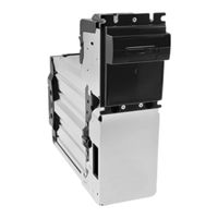
JCM GLOBAL DBV Series Integration Manual (50 pages)
Brand:
JCM GLOBAL
| Category:
Bank Note Validator
| Size: 1.54 MB
Table of Contents
Table of Contents
3
1 General Information
9
Description
9
DBV-400 Unit
9
Figure 1 DBV-400 Unit
9
Model Descriptions
10
Type Descriptions
10
Software Descriptions
10
Precautions
10
User Cautions
10
Installation Cautions
10
Figure 2 Precautionary Symbols
10
Table 1 DBV-400 Model Number Specifications
10
Table 2 DBV-400 Type Number Specifications
10
Table 3 DBV-400 Software Number Specifications
10
Mounting, Dismounting & Transportation
11
Placing Foreign Objects into the Unit
11
Preventive Maintenance
11
Banknote Fitness Requirements
12
Primary Features
12
Figure 3 Unacceptable Banknotes
12
Component Names
13
Figure 4 DBV-400 Component Names
13
2 Specifications
14
Technical Specifications
14
Environmental Specifications
14
Table 4 DBV-400 Technical Specifications
14
Table 5 DBV-400 Environmental Specifications
14
Electrical Specifications
15
Structural Specifications
15
Table 6 DBV-400 Electrical Specifications
15
Table 7 DBV-400 Structural Specifications
15
3 Installation
16
Installation Procedure
16
Entire Unit Installation
16
DIP Switch Configurations
16
Figure 5 Thread Studs Location
16
Table 8 DIP Switch Block 1 Settings
16
Table 9 DIP Switch Block 2 Settings
16
4 Connector Pin Assignments
17
MDB Photo-Coupler Isolation Connector Pin Assignments
17
Table 10 DBV-400 CN1 ID-003 MDB Photo-Coupler Isolation Connector Pin Assignments
17
RS232 Connector Pin Assignments
18
Table 11 DBV-400 CN1 ID-003 RS232 Connector Pin Assignments
18
TTL Connector Pin Assignments
19
Table 12 DBV-400 CN1 ID-003 TTL Connector Pin Assignments
19
ID-002 Pulse Connector Pin Assignments
20
Table 13 DBV-400 CN1 ID-002 Pulse Connector Pin Assignments
20
ID-044 Pulse Connector Pin Assignments
21
Table 14 DBV-400 CN1 ID-044 Pulse Connector Pin Assignments
21
ID-044 Serial Connector Pin Assignments
22
Table 15 DBV-400 CN1 ID-044 Serial Connector Pin Assignments
22
USB Connector Pin Assignments
23
Table 16 DBV-400 CN2 USB Interface Connector Pin Assignments
23
Table 17 DBV-400 CN5 USB Maintenance Interface Connector Pin Assignments
23
5 Preventive Maintenance
24
Retrieving Banknotes
24
Clearing a Banknote Jam
24
Figure 6 Retrieving Banknotes 1
24
Figure 7 Retrieving Banknotes 2
24
Figure 8 Clearing a Banknote Jam 1
24
Figure 9 Clearing a Banknote Jam 2
24
Figure 10 Clearing a Banknote Jam 3
24
Cleaning Procedure
25
Sensor and Roller Cleaning Procedure
25
Figure 11 General Cleaning Image
25
Sensor and Roller Locations
26
Figure 12 DBV-400 Sensor and Roller Cleaning Locations
26
Table 18 DBV-400 Sensor Type Cleaning Methods
26
6 Standard Interface Circuit Schematics
27
Figure 13 DBV-400 ID-003 MDB Photo-Coupler Isolation Interface Schematic Diagram
27
Standard Interface Circuit Schematics (Continued 1)
28
Figure 14 DBV-400 ID-003 RS232C Interface Schematic Diagram
28
Standard Interface Circuit Schematics (Continued 2)
29
Figure 15 DBV-400 ID-003 TTL Interface Schematic Diagram
29
Standard Interface Circuit Schematics (Continued 3)
30
Figure 16 DBV-400 ID-002 Pulse Interface Schematic Diagram
30
Standard Interface Circuit Schematics (Continued 4)
31
Figure 17 DBV-400 ID-044 Pulse Interface Schematic Diagram
31
Standard Interface Circuit Schematics (Continued 5)
32
Figure 18 DBV-400 ID-044 Serial Interface Schematic Diagram
32
Standard Interface Circuit Schematics (Continued 6)
33
Figure 19 DBV-400 USB Interface Schematic Diagram
33
7 Operational Flowchart
35
Figure 20 DBV-400 Operational Flowchart (Initializing)
35
Operational Flowchart (Continued 1)
36
Figure 21 DBV-400 Operational Flowchart (Validation)
36
Figure 22 DBV-400 Operational Flowchart (Stacking)
36
8 Troubleshooting
37
Introduction
37
Troubleshooting Overview
37
Fault Table Listings
37
Table 19 General Fault Conditions
37
Adjustment Error
38
Communication Error
38
Table 20 Adjustment Fault Conditions
38
Table 21 Communication Fault Conditions
38
LED Indication Conditions
39
LED Flash Error Code Conditions
39
Table 22 LED Flash Error Codes
39
LED Flash Reject Code Conditions
41
Table 23 LED Flash Reject Codes
41
9 Unit Dimensions
43
Entire Unit Outside Dimensions
43
Figure 23 DBV-400 Unit with JCM Standard Bezel Outside Dimensions
43
Figure 24 DBV-400 Unit with Snack Mask Bezel Outside Dimensions
43
Entire Unit Outside Dimensions (Continued)
44
Figure 25 DBV-400 Unit with TOB Type Bezel Outside Dimensions
44
10 Technical Contact Information
45
Americas
45
JCM American
45
Europe, Africa, Russia & Middle East
45
JCM Europe Gmbh
45
UK & Ireland
45
JCM Europe (UK Office)
45
Asia and Oceania
45
JCM Gold (HK) Ltd
45
Japan Cash Machine Co., Ltd. (Hq)
45
11 Index
47
Advertisement
Related Products
JCM GLOBAL DBV-400
JCM GLOBAL DT-300 Series
JCM GLOBAL DBV-500
JCM GLOBAL iVIZION2 Series
JCM GLOBAL RDM-100 Series
JCM GLOBAL Taiko PUB-11
JCM GLOBAL Taiko PUB-7
JCM GLOBAL TBV Series
JCM GLOBAL TBV-100 FLD
JCM GLOBAL TBV-100 FSH
JCM GLOBAL Categories
Bank Note Validator
Industrial Equipment
Cash Register
Ultrasonic Jewelry Cleaner
Payment Terminal
More JCM GLOBAL Manuals
Login
Sign In
OR
Sign in with Facebook
Sign in with Google
Upload manual
Upload from disk
Upload from URL