
Related Manuals for JCM GLOBAL DBV Series


Summary of Contents for JCM GLOBAL DBV Series
- Page 1 Series DBV-500 Banknote Acceptor Operation and Maintenance Manual (Revision 2) P/N 960-100933R_REV. 2 {EDP #233449} Issue #4104-SME-01-02 ©2020 JAPAN CASH MACHINE CO,. LTD. http://www.jcmglobal.com/...
- Page 2 DBV™ Series DBV-500 Banknote Acceptor Operation and Maintenance Manual Issue #4104-SME-01-02 REVISION HISTORY Rev №. Date Reason for Update Comment 10-21-14 Initial Version Added 177mm Cash Box’s Specification and Outside Dimensions in Section 1, added Panel Bracket Installa- 8-10-16 tion and Pin Assignment Note in Section 2, added Serial Number/White Level Test Steps in Section6, and updated Parts Lists and Reject Codes.
-
Page 3: Table Of Contents
DBV™ Series DBV-500 Banknote Acceptor Table of Contents Page 1 GENERAL INFORMATION ..................1-1 DBV-500 Unit ........................1-1 Product Descriptions..................... 1-2 Model Descriptions......................1-2 Type Descriptions ......................1-2 Software Descriptions ...................... 1-2 Precautions........................1-3 User Cautions ........................1-3 Installation Cautions........................1-3 Mounting, Dismounting &... - Page 4 DBV™ Series DBV-500 Banknote Acceptor Table of Contents Page Metal Lock Installation ......................... 2-3 Frame Lock Installation........................ 2-3 DIP Switch Configurations .................... 2-4 DIP Switch Block 1......................2-4 DIP Switch Block 2......................2-4 Connector Pin Assignments ..................2-5 Photo-Coupler Isolation Connector Pin Assignments ............2-5 RS232C Connector Pin Assignments..................
- Page 5 DBV™ Series DBV-500 Banknote Acceptor Table of Contents Page 5 WIRING DIAGRAMS ....................5-1 System Wiring Diagram ....................5-1 6 CALIBRATION AND TESTING ................6-1 Tool Requirement......................6-1 Installation Procedures ....................6-1 Application Software Installation ..................6-1 Driver Installation Procedure.................... 6-2 JCM Tool Suite Standard Edition Mode ...............
- Page 6 DBV™ Series DBV-500 Banknote Acceptor Table of Contents Page 8 INDEX........................8-1 A TROUBLESHOOTING ................... A-1 Introduction ........................A-1 Troubleshooting Overview ....................A-1 Fault Table Listings ......................A-1 Adjustment Error.......................... A-2 Communication Error........................A-3 LED Indication Conditions....................A-3 LED Flash Error Code Conditions ....................A-3 LED Flash Reject Code Conditions .....................
- Page 7 DBV™ Series DBV-500 Banknote Acceptor List of Figures Page Figure 1-1 DBV-500 Unit ..................1-1 Figure 1-2 Precautionary Symbols ................1-3 Figure 1-3 Unacceptable Banknotes ............... 1-4 Figure 1-4 Automatic Centering Mechanism ............1-4 Figure 1-5 DBV-500 Component Names ..............1-5 Figure 1-6 DBV-500 Unit With Standard Cash Box Outside Dimensions ....
- Page 8 DBV™ Series DBV-500 Banknote Acceptor List of Figures Page Figure 2-32 DBV-500 USB Interface Schematic Diagram ........2-18 Figure 2-33 DBV-500 ID-044 SERIAL Interface Schematic Diagram ...... 2-19 Figure 2-34 DBV-500 ID-044 SERIAL Interface Schematic Diagram ...... 2-20 Figure 2-35 DBV-500 Operational Flowchart (Initializing) ........2-21 Figure 2-36 DBV-500 Operational Flowchart (Validation) ........
- Page 9 DBV™ Series DBV-500 Banknote Acceptor List of Figures Page Figure 6-21 KS-091 Reference Paper ............... 6-5 Figure 6-22 Placing KS-091 Reference Paper 1 ............6-5 Figure 6-23 Placing KS-091 Reference Paper 2 ............6-5 Figure 6-24 Placing KS-091 Reference Paper 3 ............6-5 Figure 6-25 DIP SW1 Setting ..................
- Page 10 DBV™ Series DBV-500 Banknote Acceptor List of Figures Page Figure 6-66 Centering Test Stop Button ..............6-13 Figure 6-67 Aging Test DIP SW1 Setting ..............6-14 Figure 6-68 Aging Test DIP SW2 Setting ..............6-14 Figure 6-69 DIP SW1 #8 OFF .................. 6-14 Figure 6-70 DIP SW1 #6 and #7 ON ...............
- Page 11 DBV™ Series DBV-500 Banknote Acceptor List of Tables Page Table1-1 DBV-500 Model Number Specifications ............ 1-2 Table1-2 DBV-500 Cash Box Type Number Specifications ........1-2 Table1-3 DBV-500 Unit Type Number Specifications ..........1-2 Table1-4 DBV-500 Software Number Specifications..........1-2 Table1-5 DBV-500 Technical Specifications ............
- Page 12 THIS PAGE INTENTIONALLY LEFT BLANK P/N 960-100933R_Rev. 2 {EDP #233449} © 2020 JAPAN CASH MACHINE CO., LTD.
-
Page 13: Dbv™ Series
DBV™ Series DBV-500 Banknote Acceptor S e c t i o n 1 1 GENERAL INFORMATION This section provides a general overview of the In order to make operating this device and navigat- Series DBV-500 Banknote Acceptor Unit, ing within this manual easier, the following illust- ™... -
Page 14: Product Descriptions
Section 1 DBV™ Series DBV-500 Banknote Acceptor General Information Product Descriptions Table 1-3 lists the Unit type number descrip- tions. Model Descriptions Table 1-3 DBV-500 Unit Type Number Table 1-1 lists the product model number Specifications descriptions. Table 1-1 DBV-500 Model Number Specifications 0000000000 DBV-5 * * - (*) **(/**) DBV-5 * * - * - (*) **(/**) -
Page 15: Precautions
General Information DBV™ Series DBV-500 Banknote Acceptor Section 1 Precautions Mounting, Dismounting & Transportation Figure 1-2 Precautionary Symbols Methods for mounting, dismounting and transport- ing the unit: 1. Be sure to turn the Power OFF before mounting or removing the Unit from its permanent loca- Type 1 Type 2 Type 3... -
Page 16: Banknote Fitness Requirements
Section 1 DBV™ Series DBV-500 Banknote Acceptor General Information WARNING: To minimize risk of damage Figure 1-3 Unacceptable Banknotes to internal printed circuit boards, never allow excess fluid (e.g., from a wet cleaning cloth) to drip or leak into the Damaged or Taped Banknotes device. -
Page 17: Component Names
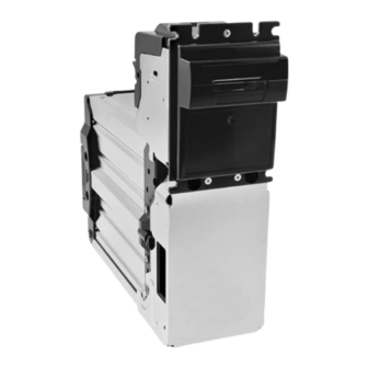
General Information DBV™ Series DBV-500 Banknote Acceptor Section 1 Component Names Figure 1-5 illustrates the DBV-500 component names and locations. Figure 1-5 DBV-500 Component Names Option Items Option Items a) Bezel b) Full-Color Indicator k) Handle c) Transport Unit l) Frame Lock d) Cash Box m) Plastic Latch e) Cash Box Latches... -
Page 18: Specifications
Section 1 DBV™ Series DBV-500 Banknote Acceptor General Information Specifications Technical Specifications Table 1-5 DBV-500 Technical Specifications 98% or greater The following Banknote types are excluded: • Banknotes with excess or poor magnetism or unclear graphics • Double (dual) Notes Acceptance Rate •... -
Page 19: Environmental Specifications
General Information DBV™ Series DBV-500 Banknote Acceptor Section 1 Environmental Specifications Table 1-6 DBV-500 Environmental Specifications Operating Temperature: -15ºC to +60ºC (5ºF to 140ºF) Storage Temperature: -20ºC to +60ºC (-4ºF to 140ºF) Relative Operating Humidity: 15% to 90% RH (non-condensed) Relative Storage Humidity: 30% to 65% RH (non-condensed) Avoid contact with direct sunlight... -
Page 20: Unit Dimensions
Section 1 DBV™ Series DBV-500 Banknote Acceptor General Information Unit Dimensions Entire Unit Outside Dimensions Figure 1-6 illustrates the DBV-500 Unit with Standard Cash Box Outside Dimensions. Figure 1-6 DBV-500 Unit With Standard Cash Box Outside Dimensions 92.5 (27) (11.4) 50.8 (11.6) Handle Specification... -
Page 21: Bezel Type A Dimensions
General Information DBV™ Series DBV-500 Banknote Acceptor Section 1 Bezel Type A Dimensions Figure 1-8 illustrates the DBV-500 Bezel Type A Outside Dimensions. Figure 1-8 DBV-500 Bezel Type A Outside NOTE: All dimensions in millimeters Dimensions 85.5 92.5 (27) 79 (Insertion Slot Width) (11.4) 50.8 (11.6) -
Page 22: Dbv-500 Installation/Maintenance Space Requirements
Section 1 DBV™ Series DBV-500 Banknote Acceptor General Information DBV-500 Installation/Maintenance Space Requirements Figure 1-10 illustrates the DBV-500 installation and maintenance space requirement. Figure 1-10 DBV-500 Installation and Mainte- nance Space Requirement Maximum Opening Angle 178º M4 Screw Hole for Frame Ground M4 screw length for Ground Wire must be less than 12mm. -
Page 23: Technical Contact Information
General Information DBV™ Series DBV-500 Banknote Acceptor Section 1 Technical Contact Information Asia and Oceania Americas JCM A MERICAN JCM A MERICAN Phone: +61-2-9648-0811 Phone: +1-702-651-0000 Fax: +61-2-9647-1438 Fax: +1-702-644-5512 Unit 21, 8 Avenue of the Americas Newington, 925 Pilot Road, Las Vegas, NV 89119 NSW 2127 Australia E-mail: support@jcmglobal.com E-mail: sales-asiapac@jcmglobal.com... - Page 24 Section 1 DBV™ Series DBV-500 Banknote Acceptor General Information THIS PAGE INTENTIONALLY LEFT BLANK P/N 960-100933R_Rev. 2 {EDP #233449} © 2020 JAPAN CASH MACHINE CO., LTD. 1 - 1 2...
-
Page 25: Installation
DBV™ Series DBV-500 Banknote Acceptor S e c t i o n 2 2 INSTALLATION Unit Installation This section provides installation and operating instructions for the DBV Series DBV-500 ™ The DBV-500 Frame Unit provides installation Banknote Acceptor Unit. The information within grooves on its surface. -
Page 26: Unit Installation With Panel Bracket
Section 2 DBV™ Series DBV-500 Banknote Acceptor Installation Unit Installation with Panel Bracket 5. From the rear side of the DBV-500 Frame, secure the Unit with the four (4) Toothed Washers (Fig- Figure 2-4 Unit Installation with Panel Bracket ure 2-7 through ) and M4 Nuts (Figure 2-3 86.4... -
Page 27: Metal Lock Installation
Installation DBV™ Series DBV-500 Banknote Acceptor Section 2 3. Secure the Door Lock A and the Door Lock B by 2. Install the Cylinder attachments (Figure 2-13 installing the single (1) 2.6x8 Phillips, Self-Tap- & ) and the Door Lock Tang (Figure 2-13 c) ping, Binding Head Screw (Figure 2-10 a). -
Page 28: Dip Switch Configurations
Section 2 DBV™ Series DBV-500 Banknote Acceptor Installation DIP Switch Configurations 5. Slide the Frame Lock assembly down to firmly latch it onto the Cash Box (Figure 2-16). This section provides the DIP Switch Block 1 Figure 2-16 Frame Lock Installation 4 (DS1) and 2 (DS2) Settings for the DBV-500 Unit. -
Page 29: Connector Pin Assignments
Installation DBV™ Series DBV-500 Banknote Acceptor Section 2 Connector Pin Assignments Table 2-3 through Table 2-13 list the DBV-500 Unit’s pin assignments. Photo-Coupler Isolation Connector Pin Assignments Table 2-3 lists the DBV-500 Photo-Coupler Isolation Unit Side Connector Pin Assignments. Table 2-3 DBV-500 Photo-Coupler Isolation Unit Side Connector Pin Assignments Power Source: MDB Connector Connector (Transport Unit Side): 74164-0006 (MOLEX) Pin No. -
Page 30: Rs232C Connector Pin Assignments
Section 2 DBV™ Series DBV-500 Banknote Acceptor Installation RS232C Connector Pin Assignments Table 2-5 lists the DBV-500 RS232C Unit Side Connector Pin Assignments. Table 2-5 DBV-500 RS232C Unit Side Connector Pin Assignments Power Source: MDB Connector Connector (Transport Unit Side): 74164-0006 (MOLEX) Pin No. -
Page 31: Ttl Connector Pin Assignments
Installation DBV™ Series DBV-500 Banknote Acceptor Section 2 TTL Connector Pin Assignments Table 2-7 lists the DBV-500 TTL Unit Side Connector Pin Assignments. Table 2-7 DBV-500 TTL Unit Side Connector Pin Assignments Power Source: MDB Connector Connector (Transport Unit Side): 74164-0006 (MOLEX) Pin No. -
Page 32: Usb Connector Pin Assignments
Section 2 DBV™ Series DBV-500 Banknote Acceptor Installation USB Connector Pin Assignments Table 2-9 lists the DBV-500 USB Unit Side Connector Pin Assignments. Table 2-9 DBV-500 USB Unit Side Connector Pin Assignments Power Source: MDB Connector Connector (Transport Unit Side): 74164-0006 (MOLEX) Pin No. -
Page 33: Id-044 Connector Pin Assignments
Installation DBV™ Series DBV-500 Banknote Acceptor Section 2 ID-044 Connector Pin Assignments Table 2-11 lists the DBV-500 ID-044 Unit Side Connector Pin Assignments. Table 2-11 DBV-500 ID-044 Unit Side Connector Pin Assignments Power Source: MDB Connector Connector (Transport Unit Side): 74164-0006 (MOLEX) Pin No. -
Page 34: Option Connector Pin Assignments
Section 2 DBV™ Series DBV-500 Banknote Acceptor Installation Option Connector Pin Assignments Table 2-13 lists the DBV-500 Option Connector Pin Assignments. Table 2-13 DBV-500 Option Connector Pin Assignments CN2 Connector (Transport Unit Side) Option Connector B10B-ZR-3.4 (JST) † Pin No. Signal Name Function No Connection... -
Page 35: Preventive Maintenance
Installation DBV™ Series DBV-500 Banknote Acceptor Section 2 Preventive Maintenance Clearing a Banknote Jam To retrieve a jammed Banknote located inside the Retrieving Banknotes Banknote Acceptor, proceed as follows: To retrieve Cash Box deposited Banknotes, 1. Press the Unit Guide Open/Close Latches (Figure perform the following steps: 2-21 a). -
Page 36: Cleaning Procedure
Section 2 DBV™ Series DBV-500 Banknote Acceptor Installation 3. When a jammed Banknote is not visible, press Figure 2-26 Jam Clear 6 the Cash Box Latches (Figure 2-23 a) located on both sides of the rear Cash Box and pull the Cash Box out of the Frame Housing. -
Page 37: Sensor And Roller Locations
Installation DBV™ Series DBV-500 Banknote Acceptor Section 2 Sensor and Roller Locations Figure 2-28 illustrates the various DBV-500 Unit’s sensor cleaning locations. Table 2-14 lists the DBV-500 sensor type cleaning methods. Figure 2-28 DBV-500 Sensor and Roller Clean- ing Locations ... - Page 38 Section 2 DBV™ Series DBV-500 Banknote Acceptor Installation THIS PAGE INTENTIONALLY LEFT BLANK P/N 960-100933R_Rev. 2 {EDP #233449} © 2020 JAPAN CASH MACHINE CO., LTD. 2 - 1 4...
-
Page 45: Operational Flowchart
Installation DBV™ Series DBV-500 Banknote Acceptor Section 2 Operational Flowchart Figure 2-35 depicts a typical DBV-500 Initialization Banknote acceptance flow process. Figure 2-35 DBV-500 Operational Flowchart (Initializing) a) Apply Power to the Unit. b) Initializing C) Return from “Stacking” Flow (Figure 2-37) c) Stand-by d) Enable Acceptance? e) External LED Display shows No Accept ... -
Page 46: Operational Flowchart (Continued 1)
Section 2 DBV™ Series DBV-500 Banknote Acceptor Installation Operational Flowchart (Continued 1) Figure 2-36 depicts a typical DBV-500 Validation Banknote acceptance flow process. Figure 2-36 DBV-500 Operational Flowchart (Validation) A) From “Initialize” Flow (Figure 2-35) a) Is the Banknote Authentic? b) Is the Banknote acceptable? c) Denomination Signal Output? d) Has STACK Command been received? -
Page 47: Operational Flowchart (Continued 2)
Installation DBV™ Series DBV-500 Banknote Acceptor Section 2 Operational Flowchart (Continued 2) Figure 2-37 depicts a typical DBV-500 Stacking Banknote acceptance flow process. Figure 2-37 DBV-500 Operational Flowchart (Stacking) B) From “Validation” Flow (Figure 2-36) a) Stack the Banknote b) Is the Cash Box full? c) Stop operation (Stacker Full Signal Output)(*2) C) To “Initializing”... - Page 48 Section 2 DBV™ Series DBV-500 Banknote Acceptor Installation THIS PAGE INTENTIONALLY LEFT BLANK P/N 960-100933R_Rev. 2 {EDP #233449} © 2020 JAPAN CASH MACHINE CO., LTD. 2 - 2 4...
-
Page 49: Communications
DBV™ Series DBV-500 Banknote Acceptor S e c t i o n 3 3 COMMUNICATIONS This section was intentionally left out due to a Non-Disclosure Agreement requirement. If this information is required, please contact the closest office location listed below: Americas Asia and Oceania JCM A... - Page 50 Section 3 DBV™ Series DBV-500 Banknote Acceptor Communications THIS PAGE INTENTIONALLY LEFT BLANK P/N 960-100933R_Rev. 2 {EDP #233449} © 2020 JAPAN CASH MACHINE CO., LTD. 3 - 2...
-
Page 51: Disassembly/Reassembly
DBV™ Series DBV-500 Banknote Acceptor S e c t i o n 4 4 DISASSEMBLY/REASSEMBLY This section provides disassembly and reassembly 2. Remove the three (3) screws (Figure 4-2 & instructions for the DBV Series DBV-500 ) securing the Bezel (Figure 4-2 b) and remove ™... -
Page 52: Side Sensor Board Removal
Section 4 DBV™ Series DBV-500 Banknote Acceptor Disassembly/Reassembly 5. Remove the four (4) screws (Figure 4-4 8. Disconnect the two (2) connectors (Figure 4-6 through ) securing the CPU Protective Sheet & ) and remove the two (2) LED Sponges (Fig- (Figure 4-4 b) and remove the CPU Protective ure 4-6 &... -
Page 53: Main Frame/Upper Guide Removal
Disassembly/Reassembly DBV™ Series DBV-500 Banknote Acceptor Section 4 Main Frame/Upper Guide Removal Inside Sensor Board Removal To remove the Main Frame and the Upper Guide, To remove the Inside Sensor Board, proceed as proceed as follows: follows: 1. Remove the two (2) screws (Figure 4-8 &... -
Page 54: Centering Motor Removal
Section 4 DBV™ Series DBV-500 Banknote Acceptor Disassembly/Reassembly 2. Disconnect the two (2) connectors (Figure 4-12 3. Remove the two (2) screws (Figure 4-14 & & b). securing the Centering Motor (Figure 4-14 e) and remove the Centering Motor. Figure 4-12 Connector Removal Figure 4-14 Centering Motor Removal Figure 4-12 Connector Removal 3. -
Page 55: Figure 4-17 Upper Guide 1 Removal
Disassembly/Reassembly DBV™ Series DBV-500 Banknote Acceptor Section 4 3. To remove the Upper Guide 2 (Figure 4-17 a), expand the Upper Guide 1 (Figure 4-17 b) by pushing gently outward on the sides as indicated by the arrows. 4. Remove the two (2) Outside Sensor FFCs (Figure 4-17 &... - Page 56 Section 4 DBV™ Series DBV-500 Banknote Acceptor Disassembly/Reassembly THIS PAGE INTENTIONALLY LEFT BLANK P/N 960-100933R_Rev. 2 {EDP #233449} © 2020 JAPAN CASH MACHINE CO., LTD. 4 - 6...
-
Page 57: Wiring Diagrams
DBV™ Series DBV-500 Banknote Acceptor S e c t i o n 5 5 WIRING DIAGRAMS • This section provides the DBV Series DBV-500 ™ System Wiring Diagram. Banknote Acceptor Unit Wiring Diagrams for the following items: System Wiring Diagram Figure 5-1 DBV-500 System Wiring Diagram CPU Board For Debugging Tool... - Page 58 Section 5 DBV™ Series DBV-500 Banknote Acceptor Wiring Diagrams THIS PAGE INTENTIONALLY LEFT BLANK P/N 960-100933R_Rev. 2 {EDP #233449} © 2020 JAPAN CASH MACHINE CO., LTD. 5 - 2...
-
Page 59: Calibration And Testing
DBV™ Series DBV-500 Banknote Acceptor S e c t i o n 6 6 CALIBRATION AND TESTING Installation Procedures This section provides Calibration and Performance Testing instructions for the DBV Series DBV-500 ™ This section provides the JCM Tool Suite Standard Banknote Acceptor Unit and contains the follow- Edition installation procedure. -
Page 60: Driver Installation Procedure
Section 6 DBV™ Series DBV-500 Banknote Acceptor Calibration and Testing Driver Installation Procedure 4. Click on the “Next>” Screen Button (Fig- ure 6-5 a) when the “ ” Screen Destination Folder DBV-500 USB Drivers need to be installed on the shown in Figure 6-5 appears. -
Page 61: Jcm Tool Suite Standard Edition Mode
Calibration and Testing DBV™ Series DBV-500 Banknote Acceptor Section 6 JCM Tool Suite Standard Edition Software Program Download Mode To download the DBV-500 Software Program, proceed as follows: The following two (2) mode feature types exist in 1. Remove electrical power from the DBV-500 the “... -
Page 62: Calibration
Section 6 DBV™ Series DBV-500 Banknote Acceptor Calibration and Testing 6. Click and hold-down the “ ” Pull- 9. When the “ ” Screen re- Service Mode JCM Downloader Suite Down Menu and select “ ” (Figure 6-16 appears, click on the center “ ”... -
Page 63: When To Calibrate
Calibration and Testing DBV™ Series DBV-500 Banknote Acceptor Section 6 When to Calibrate 2. Confirm that the KS-091 Reference Paper Tabs are hooked into both sides of the cut-out spaces Calibration should be performed when one of the of the DBV-500 (Figure 6-23 a). following four (4) conditions occur: NOTE: Be sure that the Reference 1. -
Page 64: Calibration Preparation
Section 6 DBV™ Series DBV-500 Banknote Acceptor Calibration and Testing Calibration Preparation Sensor Calibration To calibrate the DBV-500 sensors, proceed as Perform the following steps to prepare the DBV- 500 for Sensor Calibration: follows: 1. Remove electrical power from the DBV-500 1. -
Page 65: Figure 6-31 Non-Paper Calibration Completion
Calibration and Testing DBV™ Series DBV-500 Banknote Acceptor Section 6 8. Confirm the “ Remove a reference paper and NOTE: When this warning message ” message dialogue box appears. click start button. appears, the Side Sensor or the CPU Remove the KS-091 Reference Paper and click Board replacement is recommended. -
Page 66: Serial Number Setting
Section 6 DBV™ Series DBV-500 Banknote Acceptor Calibration and Testing Serial Number Setting NOTE: When clicking the “CANCEL” To set the Serial Number, proceed as follows: button (Figure 6-37 c), the Serial Number change is not saved. 1. Click the Button SERIAL NUMBER SETTING (Figure 6-40 a). -
Page 67: White Level Test
Calibration and Testing DBV™ Series DBV-500 Banknote Acceptor Section 6 Performance Tests White Level Test To perform the DBV-500 White Level Test, This section provides Performance Testing instructions proceed as follows: for the DBV-500 Unit. There are two (2) Performance Test methods: 1. -
Page 68: Performance Test Items Using A Pc
Section 6 DBV™ Series DBV-500 Banknote Acceptor Calibration and Testing 2. Click the “Performance Test” Pull-down Menu Figure 6-48 Performance Test Main Screen and select the Feed Motor Normal Test “ ” or the Feed FEED_MOTOR_FWD_TEST Motor Reverse Test “ FEED_MO- ”... -
Page 69: Stacking Movement Test
Calibration and Testing DBV™ Series DBV-500 Banknote Acceptor Section 6 Stacking Movement Test Sensor Test 1. Launch the Performance Test Main Screen (See Nine (9) Tests exist within the Sensor Test Menu. Figure 6-48 “Performance Test Main Screen” on Table 6-2 lists each Sensor Test Item function. page 6-10). -
Page 70: Dip Sw1/Sw2 Test
Section 6 DBV™ Series DBV-500 Banknote Acceptor Calibration and Testing DIP SW1/SW2 Test 1. Launch the Performance Test Main Screen (refer to Figure 6-48 “Performance Test Main Screen” To perform the DIP SW1/SW2 Test, proceed as on page 6-10). follows: 2. -
Page 71: Led Test
Calibration and Testing DBV™ Series DBV-500 Banknote Acceptor Section 6 LED Test Centering Movement Test To perform the LED Test, proceed as follows: To perform the Centering Mechanism Movement Test, proceed as follows: 1. Launch the Performance Test Main Screen (Refer to “Performance Test Main Screen”... -
Page 72: Performance Test Without A Pc
Section 6 DBV™ Series DBV-500 Banknote Acceptor Calibration and Testing Performance Test without a PC Table 6-3 lists the items and DIP Switch 1 settings for the DBV-500 Performance Test. Table 6-3 Performance Test Items and DIP Switch 1 Settings DIP Switch Setting Test Item Test Purpose... -
Page 73: Sensor Test
Calibration and Testing DBV™ Series DBV-500 Banknote Acceptor Section 6 Sensor Test Acceptance Test To perform the Sensor Test, proceed as follows: To perform the Acceptance Test, proceed as follows: 1. Remove electrical power from the DBV-500 Unit. 1. Remove electrical power from the DBV-500 2. -
Page 74: Led Test
Section 6 DBV™ Series DBV-500 Banknote Acceptor Calibration and Testing LED Test Other Performance Tests To perform the Sensor Test, proceed as follows: To perform the other Performance Tests, proceed as follows: 1. Remove electrical power from the DBV-500 Unit. 1. -
Page 75: Exploded Views & Parts Lists
DBV™ Series DBV-500 Banknote Acceptor S e c t i o n 7 7 EXPLODED VIEWS & PARTS LISTS This section provides product exploded views and • DBV-500 Entire Unit parts lists for the DBV Series DBV-500 Banknote ™ • DBV-500 Main Unit Acceptor Unit. -
Page 76: Dbv-500 Entire Unit Parts List
Section 7 DBV™ Series DBV-500 Banknote Acceptor Exploded Views & Parts Lists DBV-500 Entire Unit Parts List Table 7-1 DBV-500 Entire Unit Parts List Ref No. EDP No. Description Remark DBV-500-SD/SU 00000-010000-00 UNIT DBV-500 BEZEL UNIT TYPE-A Bezel Type A See Table 1-2 on page 1-2. -
Page 77: Dbv-500 Main Unit Exploded View
Exploded Views & Parts Lists DBV™ Series DBV-500 Banknote Acceptor Section 7 DBV-500 Main Unit Exploded View Figure 7-2 DBV-500 Main Unit Exploded View Figure 7-2 DBV-500 Main Unit Exploded View P/N 960-100933R_Rev. 2 {EDP #233449} © 2020 JAPAN CASH MACHINE CO., LTD. 7 - 3... -
Page 78: Dbv-500 Main Unit Parts List
Section 7 DBV™ Series DBV-500 Banknote Acceptor Exploded Views & Parts Lists DBV-500 Main Unit Parts List Table 7-3 DBV-500 Main Unit Parts List Ref No. EDP No. Description Remark 239924 BEZEL_TYPE1 Bezel Type A 239926 BEZEL_TYPE2 Bezel Type B Bezel Type 1 Light 239925 BEZEL_TYPE1_LIGHT_GU... -
Page 79: Dbv-500 Upper Guide Exploded View
Exploded Views & Parts Lists DBV™ Series DBV-500 Banknote Acceptor Section 7 DBV-500 Upper Guide Exploded View Figure 7-3 DBV-500 Upper Guide Exploded View Figure 7-3 DBV-500 Upper Guide Exploded View P/N 960-100933R_Rev. 2 {EDP #233449} © 2020 JAPAN CASH MACHINE CO., LTD. 7 - 5... -
Page 80: Dbv-500 Upper Guide Parts List
Section 7 DBV™ Series DBV-500 Banknote Acceptor Exploded Views & Parts Lists DBV-500 Upper Guide Parts List Table 7-4 DBV-500 Upper Guide Parts List Ref No. EDP No. Description Remark 4104-3521-06-003A-01A INSIDE SENSOR 237080 Service Part BOARD 231530 3521-05-003A INSIDE SENSOR FFC 231400 Seal Sponge Service Part... - Page 81 Exploded Views & Parts Lists DBV™ Series DBV-500 Banknote Acceptor Section 7 Table 7-4 DBV-500 Upper Guide Parts List Ref No. EDP No. Description Remark Centering Motor Harness Assembly 235094 4104-3521-05-008-01 Service Part Centering Gear D 231388 CENT_GE_D Press-in fit required for assembly 231464 CT_SH_D Centering Shaft D...
-
Page 82: Dbv-500 Main Frame Exploded View
Section 7 DBV™ Series DBV-500 Banknote Acceptor Exploded Views & Parts Lists DBV-500 Main Frame Exploded View Figure 7-4 DBV-500 Main Frame Exploded View Figure 7-4 DBV-500 Main Frame Exploded View P/N 960-100933R_Rev. 2 {EDP #233449} © 2020 JAPAN CASH MACHINE CO., LTD. 7 - 8... -
Page 83: Dbv-500 Main Frame Parts List
Exploded Views & Parts Lists DBV™ Series DBV-500 Banknote Acceptor Section 7 DBV-500 Main Frame Parts List Table 7-5 DBV-500 Main Frame Parts List Ref No. EDP No. Description Remark 242620 Main Frame 231389 TR_GE_A Transport Gear A 231393 TR_WORM_WHEEL Transport Worm Wheel 231470 TR_SH_E... -
Page 84: Bv-500 Series Cash Box Option Parts Exploded View
Section 7 DBV™ Series DBV-500 Banknote Acceptor Exploded Views & Parts Lists BV-500 Series Cash Box Option Parts Exploded View Figure 7-5 DBV-500 Series Cash Box Option Parts Exploded Door Lock Option OP2 OP3 Handle Option OP11 OP3* Frame Lock Option OP10 OP14 OP13... -
Page 85: Dbv-500 Series Cash Box Option Parts List
Exploded Views & Parts Lists DBV™ Series DBV-500 Banknote Acceptor Section 7 DBV-500 Series Cash Box Option Parts List Table 7-6 DBV-500 Option Parts List Ref No. EDP No. Description Remark Designated For S-Box S3100 (with 152089 Lock Handle and Door Lock options) 026378 Lock... - Page 86 Section 7 DBV™ Series DBV-500 Banknote Acceptor Exploded Views & Parts Lists THIS PAGE INTENTIONALLY LEFT BLANK P/N 960-100933R_Rev. 2 {EDP #233449} © 2020 JAPAN CASH MACHINE CO., LTD. 7 - 1 2...
-
Page 87: Index
DBV™ Series DBV-500 Banknote Acceptor S e c t i o n 8 8 INDEX Calibration Safety Methods of ...6-4 pictographs indicating ...1-1 Contact Information 1 to 3 symbols inside boxed area Software Descriptions Address and Telephone Numbers for ...1-11 Product Number Specifications of ...1-2 Special Notes italic text highlights... - Page 88 Section 8 DBV™ Series DBV-500 Banknote Acceptor Index THIS PAGE INTENTIONALLY LEFT BLANK P/N 960-100933R_Rev. 2 {EDP #233449} © 2020 JAPAN CASH MACHINE CO., LTD. 8 - 2...
-
Page 89: A Troubleshooting
DBV™ Series DBV-500 Banknote Acceptor A p p e n d i x A A TROUBLESHOOTING This section provides troubleshooting instructions in locating any causes of failure and the possible for the DBV Series DBV-500 Banknote Acceptor fault location. ™ Unit, including the following information: Perform all repairs by referring to Calibration and •... -
Page 90: Adjustment Error
Section A DBV™ Series DBV-500 Banknote Acceptor TroubleShooting Table A-1 General Fault Conditions (Continued) Symptoms/Error Possible Fault Causes Corrective Action Required Messages Dirt and/or stains on the Clean the Transport path. Refer to “Sensor and Roller Cleaning Procedure” on page 2-12. Rollers and Lenses The Unit has been disassembled, and calibration... -
Page 91: Communication Error
TroubleShooting DBV™ Series DBV-500 Banknote Acceptor Section A Communication Error Table A-3 lists the various possible DBV-500 Unit Communication fault conditions. Table A-3 Communication Fault Conditions Symptoms/Error Possible Fault Causes Corrective Action Required Messages DIP Switch settings are Set all DIP Switches to OFF and then set the DIP Switch correctly while referring to the “Software Information Sheet”. - Page 92 Section A DBV™ Series DBV-500 Banknote Acceptor TroubleShooting Table A-4 LED Flash Error Codes (Continued) Normal Performance Operation Test Error Causes and Solutions Sequence Sequence EEPROM reading, writing and/or saving was not properly performed. [Solution] Perform the Sensor Calibration procedure. If the error is not resolved, White White check that the following part is properly assembled and/or Harness connected.
- Page 93 TroubleShooting DBV™ Series DBV-500 Banknote Acceptor Section A Table A-4 LED Flash Error Codes (Continued) Normal Performance Operation Test Error Causes and Solutions Sequence Sequence Sensors detect Banknotes occurring with abnormal timing. [Solution] Check that the following parts are properly assembled and/or Harness connected.
-
Page 94: Led Flash Reject Code Conditions
Section A DBV™ Series DBV-500 Banknote Acceptor TroubleShooting LED Flash Reject Code Conditions Table A-5 lists the various LED Flash Reject Code causes and solutions for Banknotes. Table A-5 LED Flash Reject Codes Normal Performance Operation Test Error Causes and Solutions Sequence Sequence Sensors detected improper levels. - Page 95 TroubleShooting DBV™ Series DBV-500 Banknote Acceptor Section A Table A-5 LED Flash Reject Codes (Continued) Normal Performance Operation Test Error Causes and Solutions Sequence Sequence While initializing, a Banknote was detected in the Unit. [Solution] Clean or adjust the following parts. Remaining Green Green...
-
Page 96: Dbv-500 Maintenance Equipment
Section A DBV™ Series DBV-500 Banknote Acceptor TroubleShooting Maintenance Equipment This portion provides product information for the DBV-500 Maintenance Equipment. DBV-500 Maintenance Equipment Figure A-1 Additional Maintenance Equipment Requirements NOTE: Only the European NOTE: Only the European Style Connector Version is shown here. Version is shown here. -
Page 97: B Glossary
DBV™ Series DBV-500 Banknote Acceptor A p p e n d i x B B GLOSSARY Banknote Jam on occasion, wrinkled or damaged Banknotes become stuck within the mechanical area of the Validation Unit. This condition may occur due to acceptance of a severely de- graded Banknote, or due to a feed error occurring in the Transport Path. - Page 98 Section B DBV™ Series DBV-500 Banknote Acceptor Glossary an acronym for Central Processing Unit. In most systems the CPU is a multi-pin semi- conductor device mounted on a Printed Circuit Board (PCB). It is used in conjunction with other interface microchips and memory devices, and is responsible for controlling the overall operation of the equipment into which it is installed...
- Page 99 Glossary DBV™ Series DBV-500 Banknote Acceptor Section B 14 LED an acronym for Light Emitting Diode. An LED is Semiconductor Device which turned on, emits a signal output in the visible light range. Available in a variety of colors, LEDs are cost effective and are commonly used as Indicator Lights in a variety of equipment devices.
- Page 100 Section B DBV™ Series DBV-500 Banknote Acceptor Glossary 22 TTL an acronym for Transistor to Transistor Logic levels... 1-6 23 USB an acronym for Universal Serial Bus. The USB protocol is a widely used serial-based communications data bus which allows a large number of peripheral devices to com- municate with a host controller, and is commonly found on nearly all personal down- load data files into flash memory quickly and easily from a PC...
- Page 101 DBV™ Series DBV-500 Banknote Acceptor P/N 960-100933R_Rev. 2 {EDP #233449} © 2020 JAPAN CASH MACHINE CO., LTD.
- Page 102 DBV™ Series DBV-500 Banknote Acceptor Issue #4104-SME-01-02 P/N 960-100933R_Rev. 2 {EDP #233449} © 2020 JAPAN CASH MACHINE CO., LTD.
Need help?
Do you have a question about the DBV Series and is the answer not in the manual?
Questions and answers