Sign In
Upload
Manuals
Brands
IBM Manuals
Server
Power Systems Series
IBM Power Systems Series Manuals
Manuals and User Guides for IBM Power Systems Series. We have
10
IBM Power Systems Series manuals available for free PDF download: Handbook, Manual, Site And Hardware Planning, Problem Analysis, System Parts, And Locations, Installing
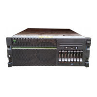
IBM Power Systems Series Handbook (336 pages)
Finding parts, locations, and addresses
Brand:
IBM
| Category:
Server
| Size: 48.36 MB
Table of Contents
Table of Contents
5
Safety Notices
7
What's New in Parts, Locations, and Addresses
14
Part Locations and Location Codes
15
8202-E4B or 8205-E6B
15
8202-E4B or 8205-E6B Locations
18
8202-E4C, 8202-E4D, 8205-E6C, or 8205-E6D
27
8202-E4C, 8202-E4D, 8205-E6C, or 8205-E6D Locations
30
8231-E2B
38
8231-E2B Locations
41
8231-E1C, 8231-E1D, 8231-E2C, 8231-E2D, or 8268-E1D
47
8231-E1C, 8231-E1D, 8231-E2C, 8231-E2D, or 8268-E1D Locations
50
8233-E8B and 8236-E8C
56
8233-E8B and 8236-E8C Locations
59
8248-L4T, 8408-E8D, or 9109-RMD
66
8248-L4T, 8408-E8D, or 9109-RMD Locations
69
9117-MMB and 9179-MHB
76
9117-MMB and 9179-MHB Locations
79
8412-EAD, 9117-MMC, 9117-MMD, 9179-MHC, or 9179-MHD
85
8412-EAD, 9117-MMC, 9117-MMD, 9179-MHC, or 9179-MHD Locations
88
9119-Fhb
94
9119-FHB Locations
97
9125-F2C
106
9125-F2C Locations
109
5786, 5787, 7031-D24, and 7031-T24
142
5786, 5787, 7031-D24, and 7031-T24 Locations
145
5796 And 7314-G30
149
5796 And 7314-G30 Locations
152
5802 And 5877
154
5802 And 5877 Locations
157
5803 And 5873
161
5803 And 5873 Locations
164
5886 Locations
170
5887 Locations
174
5888 Or EDR1 Pcie Storage Enclosure
176
5888 Or EDR1 Pcie Storage Enclosure Locations
179
Addresses
182
8202-E4B or 8205-E6B Addresses
183
8202-E4C, 8202-E4D, 8205-E6C, or 8205-E6D Addresses
184
8231-E2B Addresses
185
8231-E1C, 8231-E1D, 8231-E2C, 8231-E2D, or 8268-E1D Addresses
185
8233-E8B and 8236-E8C Addresses
186
8408-E8D or 9109-RMD Addresses
187
9117-MMB and 9179-MHB Addresses
188
8412-EAD, 9117-MMC, 9117-MMD, 9179-MHC, or 9179-MHD Addresses
190
5786, 5787, 7031-D24, and 7031-T24 Addresses
192
5796 And 7314-G30 Addresses
193
5802 And 5877 Addresses
193
5803 And 5873 Addresses
194
5886 Addresses
196
5888 Or EDR1 Pcie Storage Enclosure Addresses
197
System Parts
198
8202-E4B or 8205-E6B System Parts
198
8202-E4C, 8202-E4D, 8205-E6C, or 8205-E6D System Parts
206
Disk Drive and Solid-State Drive System Parts
212
Keyboard Parts
215
8231-E2B System Parts
216
8231-E1C, 8231-E1D, 8231-E2C, 8231-E2D, or 8268-E1D System Parts
221
Disk Drive and Solid-State Drive System Parts
226
Keyboard Parts
229
8233-E8B and 8236-E8C System Parts
229
8248-L4T, 8408-E8D, or 9109-RMD System Parts
239
Disk Drive and Solid-State Drive System Parts
245
Keyboard Parts
248
Wrap Plug Parts
249
9117-MMB and 9179-MHB System Parts
249
Disk Drive and Solid-State Drive System Parts
256
Keyboard Parts
258
Wrap Plug Parts
260
8412-EAD, 9117-MMC, 9117-MMD, 9179-MHC, or 9179-MHD System Parts
260
Disk Drive and Solid-State Drive System Parts
270
Keyboard Parts
273
Wrap Plug Parts
274
9119-FHB System Parts
275
9125-F2C System Parts
287
5786, 5787, 7031-D24, and 7031-T24 System Parts
298
5796 And 7314-G30 System Parts
303
5802 And 5877 System Parts
306
5803 And 5873 System Parts
309
5886 System Parts
312
Disk Drive and Solid-State Drive System Parts
313
5887 System Parts
316
Disk Drive and Solid-State Drive System Parts
319
5888 Or EDR1 Pcie Storage Enclosure System Parts
322
Notices
325
Trademarks
326
Electronic Emission Notices
326
Class a Notices
326
Class B Notices
330
Terms and Conditions
333
Advertisement
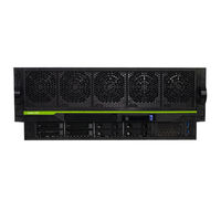
IBM Power Systems Series Manual (296 pages)
Temple's Zeppelin procedures for install, remove, replace
Brand:
IBM
| Category:
Server
| Size: 11.33 MB
Table of Contents
Table of Contents
3
Control Panel
5
Removing or Replacing the Control Panel
5
Preparing the System
5
Removing the Control Panel
7
Replacing the Control Panel
8
Preparing the System for Operation
9
Removing or Replacing the Control Panel Display
10
Preparing the System
10
Removing the Control Panel Display
12
Replacing the Control Panel Display
13
Preparing the System for Operation
14
Fans
15
Removing and Replacing a Fan
15
Preparing the System to Remove and Replace a Fan
15
Removing a Fan
20
Replacing a Fan
21
Preparing the System for Operation
22
Power Supplies
25
Removing and Replacing a Power Supply
25
Preparing the System to Remove and Replace a Power Supply
25
Removing a Power Supply
30
Replacing a Power Supply
31
Preparing the System for Operation
32
Front USB Cable
35
Removing and Replacing the Front USB Cable
35
Preparing the System to Remove and Replace a Front USB Cable
35
Removing the Front USB Cable
46
Replacing the Front USB Cable
47
Preparing the System for Operation
48
Rear USB Cable
57
Removing and Replacing the Rear USB Cable
57
Preparing the System to Remove and Replace a Rear USB Cable
57
Removing the Rear USB Cable
63
Replacing the Rear USB Cable
66
Preparing the System for Operation
69
Time-Of-Day Battery
73
Removing and Replacing the Time-Of-Day Battery
73
Preparing to Remove and Replace the Time-Of-Day Battery
73
Removing the Time-Of-Day Battery
74
Replacing the Time-Of-Day Battery
77
Preparing the System for Operation
78
SAS Cables
83
Removing and Replacing the Externally-Secured SAS Cables
83
Preparing the System to Remove and Replace the SAS Cables
83
Removing the SAS Cables
88
Replacing the SAS Cables
105
Preparing the System for Operation
120
Removing Internally-Secured SAS Cables and Replacing with Externally-Secured SAS Cables
121
Memory Modules and Memory Risers
189
Memory Modules
189
Installing a Memory Modules
189
Removing and Replacing Memory Modules in the System
198
Plugging Rules for Memory Modules in the System
211
Permanently Removing Memory Modules from the System
211
Memory Riser
220
Installing a Memory Riser
220
Removing and Replacing Memory Riser in the System
228
Permanently Removing a Memory Riser from the System
238
Service Processor Card Assembly
247
Removing and Replacing the Service Processor Card Assembly
247
Preparing the System to Remove and Replace the Service Processor Card Assembly
247
Removing the Service Processor Card Assembly
250
Replacing the Service Processor Card Assembly
251
Preparing the System for Operation
254
System Processor Modules
257
Removing and Replacing the System Processor Module
257
Preparing the System to Remove and Replace a System Processor Module
257
Removing the System Processor Module
264
Replacing the System Processor Module
271
Preparing the System for Operation after Removing and Replacing a System Processor Module
281
Common Things
285
Placing a 9040-MR9 System into the Service Position
285
Placing a 9040-MR9 System into the Operating Position
286
Removing the Service Access Cover from a 9040-MR9 System
287
Installing the Service Access Cover on the 9040-MR9 System
288
Disconnecting the Power Cords from the 9040-MR9 System
289
Connecting the Power Cords to the 9040-MR9 System
292
Removing the Front Cover from a 9040-MR9 System
292
Installing the Front Cover on a 9040-MR9 System
293
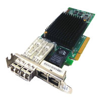
IBM Power Systems Series Manual (245 pages)
Managing PCIe adapters for the Machine Types 9008, 9009, 9040, 9080, 9223, and the EMX0 PCIe3 expansion drawer
Brand:
IBM
| Category:
PCI Card
| Size: 3.72 MB
Table of Contents
Table of Contents
3
Safety Notices
5
Managing Pcie Adapters
15
PCI Express
15
Pcie Slot Compatibility
15
Overview of Managing Pcie Adapters
15
Partitioning with Multi-Adapter Configurations
16
Handling Static-Sensitive Devices
16
Multi-Initiator and High Availability
16
HA Two-System/Ha Single System Configuration
16
Pcie Adapters for IBM Power Systems Servers
17
Managing Pcie Adapters for the 9008-22L, 9009-22A, or 9223-22H System
17
Managing Pcie Adapters for the 9009-41A, 9009-42A, or 9223-42H System
18
SAS RAID Internal Adapters and Controllers
19
Managing Pcie Adapters for the 9040-MR9 System
20
Managing Pcie Adapters for the 9080-M9S System
23
SAS RAID Controllers Supported for the 9080-M9S System
24
Pcie Adapter Information by Feature Code
25
Reference Information for Managing Pcie Adapters
63
Installing the AIX Device Driver Software
63
Verifying the AIX Device Driver Software
64
Upgrading a SAS RAID Storage Adapter
64
Pcie Adapter Details
64
Pcie Binary Synchronous Adapter
65
Operating System or Partition Requirements
66
FC 5260 and FC EL4M Pcie2 4-Port 1 Gbe Adapter
67
FC 5899 and FC EL4L Pcie2 4-Port 1 Gbe Adapter
68
Adapter LED States
69
Pcie POWER GXT145 Graphics Accelerator Adapter and Converter Cable
70
Preparing for Installation
71
Installing the Adapter
71
Verifying the Adapter Installation
71
Checking the Device Driver Software Installation
72
Checking the Console
72
Checking the Adapter Installation
72
Pcie 8 Gb 2-Port Fibre Channel Adapter
74
Adapter Specifications
75
Slot Requirement
75
Cables
76
Adapter LED
76
Replacing Fibre Channel Adapters by Using Hot Swap
77
Power-On Self Test (POST) Conditions and Results
77
Pcie 4-Port Async EIA-232 1X Adapter
79
Cable for the Pcie 4-Port Async EIA-232 1X Adapter
80
Replacing Fibre Channel Adapters Using Hot Swap
84
Power GXT145 PCI Express Graphics Accelerator
85
Pcie3 LP 2-Port 10 Gbe NIC and Roce SR Adapter
88
Form Factor
94
Attributes Provided
94
Transceivers
94
Cable and Transceiver Information
94
The Pcie3 2-PORT 25/10 Gb NIC & Roce SFP28 Adapter
95
Cable Type and Distance (10 Gb/S)
95
Optical Transceivers and Cables
95
Pcie3 2-Port 10 Gbe NIC & Roce SFP+ Copper Adapter
100
Pcie3 2-Port 40 Gbe NIC Roce QSFP+ Adapter
104
Pcie3 2-Port 100 Gb EDR Infiniband Adapter
108
Pcie3 2-Port 100 Gbe NIC & Roce QSFP28 Adapter
110
Cable and Transceiver Matrix
112
Pcie3 X16 1-Port 100 Gb EDR Infiniband Adapter
113
Pcie2 3D Graphics Adapter X1 (FC EC42)
115
Pcie2 LP 4-Port USB 3.0 Adapter
118
IBM Installation Toolkit for Powerlinux
118
Pcie2 LP 3D Graphics Adapter X16 (FC EC51)
121
Pcie3 2X4 Nvme M.2 Internal Carrier Adapter (FC EC59)
123
Pcie3 X8 Nvme 1.6 TB SSD Nvme Flash Adapter
125
Pcie3 X8 Nvme 3.2 TB SSD Nvme Flash Adapter
127
Pcie3 X8 Nvme 6.4 TB SSD Nvme Flash Adapter
129
Pcie4 X16 1-Port EDR 100 GB IB Connectx-5 CAPI Capable Adapter
131
Pcie4 X16 2-Port EDR 100 GB IB Connectx-5 CAPI Capable Adapter
133
Pcie4 2-Port 100 Gbe Roce X16 Adapter (FC EC66 and EC67; CCIN 2CF3)
135
Pcie4 X16, 1-Port HDR 100 Gb Infiniband Connectx-6 Adapter
139
Pcie4 X16, 2-Port HDR 100 Gb Infiniband Connectx-6 Adapter
142
Pcie3 Cable Adapter (FC EJ05; CCIN 2B1C)
145
Pcie3 Cable Adapter (FC EJ07; CCIN 6B52)
147
Pcie3 SAS RAID Quad-Port 6 Gb Adapter (FC EJ0J and FC EL59; CCIN 57B4)
149
Pcie3 RAID SAS Quad-Port 6 Gb Adapter (FC EJ0K; CCIN 57B4)
152
Pcie3 RAID SAS Quad-Port 6 Gb LP Adapter
158
Pcie3 4 X8 SAS Port Adapter
160
Pcie3 12 GB Cache RAID + SAS Adapter Quad-Port 6 Gb X8
163
Pcie3 Cable Adapter (FC EJ19; CCIN 6B53)
166
Pcie3 X8 SAS RAID Internal Adapter 6 Gb
168
Single Adapter Configuration
168
Two Adapters Split Storage Backplane Configuration
168
Pcie3 X8 Cache SAS RAID Internal Adapter 6 Gb
170
Adapter Caching
172
Pcie3 Cable Adapter
178
Pcie Cryptographic Coprocessor
181
4767-002 Cryptographic Coprocessor
183
Pcie3 16 Gb 2-Port Fibre Channel Adapter
186
Pcie2 8 Gb 2-Port Fibre Channel Adapter
192
Pcie3 4-Port (2X10 Gb Fcoe, 2X1 Gbe) SFP+ Adapter
195
Pcie3 4-Port (10 Gb Fcoe and 1 Gbe) Copper and RJ45 Adapter
198
Pcie3 LP 4-Port (10 Gb Fcoe and 1 Gbe) Copper and RJ45 Adapter
202
Pcie3 4-Port (10 Gb Fcoe and 1 Gbe) LR and RJ45 Adapter
205
Pcie2 4-Port (10 Gb + 1 Gbe) SR / Copper SFP +RJ45 Adapter
208
Pcie2 2-Port 10 Gbe Baset RJ45 Adapter
213
Pcie2 LP 8 Gb 4-Port Fibre Channel Adapter
215
Pcie2 FH 4-Port 8 Gb Fibre Channel Adapter
218
Pcie3 4-Port 10 Gbe SR Adapter
221
Pcie3 4-Port 10 Gbe SFP+ Copper Adapter
224
Nvme 400 GB Mainstream Solid-State Drive (FC ES14)
227
Pcie3 X8 2-Port Fibre Channel (32 Gb/S)
228
Pcie3 X8 4-Port Fibre Channel (16 Gb/S)
230
Notices
233
Accessibility Features for IBM Power Systems Servers
234
Interface Information
234
Privacy Policy Considerations
235
Trademarks
235
Electronic Emission Notices
236
Class a Notices
236
Class B Notices
239
Terms and Conditions
241
Advertisement
IBM Power Systems Series Site And Hardware Planning (206 pages)
Brand:
IBM
| Category:
Server
| Size: 15.76 MB
Table of Contents
Table of Contents
5
Safety Notices
7
Site and Hardware Physical Planning Overview
17
Planning Activities
19
Planning Task Checklist
19
General Considerations
19
Site Preparation and Physical Planning Guidelines
20
Site and Hardware Planning
23
Hardware Specification Sheets
23
Server Specifications
23
Model 8408-44E and 8408-E8E Server Specifications
23
Model 8408-44E Technical Documentation for EU Regulation 617/2013
28
Model 8408-E8E Technical Documentation for EU Regulation 617/2013
29
Expansion Unit and Migration Tower Specifications
30
5887 Expansion Unit
30
EMX0 Pcie Gen3 I/O Expansion Drawer (Feature Code EMX0)
31
5147-024, ESLL, and ESLS Storage Enclosures
32
Rack Specifications
33
Model 0550 and 9406-830 Rack
34
Model 0551 Rack
35
Model 0551, 0553, 0555, and 7014 Rack Configurations
37
Model 0551 and 9406-270 Rack
44
Model 0554 and 7014-S11 Rack
46
Model 0555 and 7014-S25 Rack
48
Model 7014-T00 Rack
52
Planning for the 7014-T00 and 7014-T42 Racks
52
Model 7014-T00 Rack with Optional DC Power Distribution Panel
54
Model 7014-T42, 7014-B42, and 0553 Rack
56
7014-T00, 7014-T42, and 0553 Supported Feature Codes
60
7014-T00, 7014-T00, and 0553 Racks Multiple Attachment
62
7014-T00, 7014-T42, and 0553 Rack Weight Distribution and Floor Loading
62
Model 7953-94X and 7965-94Y Rack
64
Planning for the 7953-94X and 7965-94Y Rack
64
Cabling the 7953-94X and 7965-94Y Rack
66
Side Stabilizing Outriggers
68
Multiple Racks
69
Model 1164-95X Rear Door Heat Exchanger
70
Model 1164-95X Rear Door Heat Exchanger Water Cooling Specifications and Requirements
73
Model 7965-S42 Rack Specifications
77
Planning for the 7965-S42 Rack
77
Cabling the 7965-S42 Rack
81
Multiple Racks
83
Model 7965-S42 Supported Feature Codes
84
Model 1164-95X Rear Door Heat Exchanger
85
Model 1164-95X Rear Door Heat Exchanger Water Cooling Specifications and Requirements
88
Hardware Management Console Specifications
92
7042-C07 Desktop Hardware Management Console Specifications
92
7042-C08 Hardware Management Console Specifications
93
7042-CR7 Hardware Management Console Specifications
94
7042-CR8 Hardware Management Console Specifications
95
7042-CR9 Hardware Management Console Specifications
96
7063-CR1 Hardware Management Console Specifications
98
Rack Switch Specifications
100
G8052R Rackswitch Specification Sheet
100
G8124ER Rackswitch Specification Sheet
100
G8264R Rackswitch Specification Sheet
101
G8316R Rackswitch Specification Sheet
102
Rack Installation Specifications for Racks Not Purchased from IBM
102
Planning for Power
109
Determining Your Power Requirements
109
Server Information Form 3A
110
Workstation Information Form 3B
111
Plugs and Receptacles
111
Supported Power Cords
111
Supported PDU Power Cords
121
Modification of IBM-Provided Power Cords
124
Uninterruptible Power Supply
125
Power Distribution Unit and Power Cord Options for 0551, 0553, 0555, 7014, 7953, and 7965 Racks
127
Calculating the Power Load for 7188 or 9188 Power Distribution Units
133
Planning for Cables
135
Cable Management
136
Power Cord Routing and Retention
137
Planning for Serial-Attached SCSI Cables
138
SAS Cabling for the 5887 Disk Drive Enclosure
163
SAS Cabling for the ESLL and ESLS Storage Enclosures
180
Planning for High Availability
189
Understanding Workloads
189
Planning for High Availability by Using Live Partition Mobility (LPM)
189
Planning for High Availability by Using Powerha Systemmirror
190
Notices
193
Accessibility Features for IBM Power Systems Servers
194
Privacy Policy Considerations
195
Trademarks
196
Electronic Emission Notices
196
Class a Notices
196
Class B Notices
200
Terms and Conditions
203
IBM Power Systems Series Site And Hardware Planning (164 pages)
Brand:
IBM
| Category:
Server
| Size: 3.98 MB
Table of Contents
Table of Contents
3
Safety Notices
5
Site and Hardware Physical Planning Overview
15
Planning Activities
17
Planning Task Checklist
17
General Considerations
17
Site Preparation and Physical Planning Guidelines
18
Site and Hardware Planning
21
Hardware Specification Sheets
21
Server Specifications
21
Expansion Unit and Migration Tower Specifications
32
Rack Specifications
36
Hardware Management Console Specifications
78
Rack Switch Specifications
81
Rack Installation Specifications for Racks that Are Not Purchased from IBM
84
Planning for Power
92
Determining Your Power Requirements
92
Plugs and Receptacles
94
Modification of IBM-Provided Power Cords
109
Uninterruptible Power Supply
110
Power Distribution Unit and Power Cord Options for 7014, 7953, and 7965 Racks
111
Calculating the Power Load for 7188 or 9188 Power Distribution Units
119
Planning for Cables
121
Cable Management
121
Planning for Serial-Attached SCSI Cables
125
Notices
153
Accessibility Features for IBM Power Systems Servers
154
Privacy Policy Considerations
155
Trademarks
155
Electronic Emission Notices
155
Class a Notices
156
Class B Notices
159
Terms and Conditions
161
IBM Power Systems Series Problem Analysis, System Parts, And Locations (134 pages)
Brand:
IBM
| Category:
Server
| Size: 3.11 MB
Table of Contents
Table of Contents
3
Safety Notices
5
Beginning Troubleshooting and Problem Analysis
15
Determining the Problem Analysis Procedure to Perform
15
Resolving a BMC Access Problem
16
Resolving a Power Problem
19
Resolving a System Firmware Boot Failure
19
Resolving a VGA Monitor Problem
21
Resolving an Operating System Boot Failure
21
Resolving a Sensor Indicator Problem
23
Resolving a Hardware Problem
24
Resolving a Pcie Adapter or Device Problem
25
Resolving a Network Adapter Problem
27
Resolving an Nvme Flash Adapter Problem
29
Resolving a Storage Device Problem
29
Identifying the Location of the Pcie Adapter by Using the Slot Number
30
Identifying the Location of the Nvme Flash Adapter
31
Identifying the Location of the Storage Device
31
User Guides for Pcie Adapters
31
Identifying a Service Action
32
Identifying a Service Action by Using System Event Logs
32
Identifying Service Action Keywords in System Event Logs
37
Identifying a Service Action by Using Sensor and Event Information
38
Isolation Procedures
63
EPUB_PRC_FIND_DECONFIGURE_PART Isolation Procedure
63
EPUB_PRC_SP_CODE Isolation Procedure
64
EPUB_PRC_PHYP_CODE Isolation Procedure
64
EPUB_PRC_ALL_PROCS Isolation Procedure
64
EPUB_PRC_ALL_MEMCRDS Isolation Procedure
65
EPUB_PRC_LVL_SUPPORT Isolation Procedure
66
EPUB_PRC_MEMORY_PLUGGING_ERROR Isolation Procedure
66
EPUB_PRC_FSI_PATH Isolation Procedure
66
EPUB_PRC_PROC_AB_BUS Isolation Procedure
67
EPUB_PRC_PROC_XYZ_BUS Isolation Procedure
68
EPUB_PRC_EIBUS_ERROR Isolation Procedure
69
EPUB_PRC_POWER_ERROR Isolation Procedure
70
EPUB_PRC_MEMORY_UE Isolation Procedure
70
EPUB_PRC_HB_CODE Isolation Procedure
71
EPUB_PRC_TOD_CLOCK_ERR Isolation Procedure
72
EPUB_PRC_COOLING_SYSTEM_ERR Isolation Procedure
73
Verifying a Repair
74
Collecting Diagnostic Data
74
Contacting IBM Service and Support
75
Finding Parts and Locations
77
5104-22C or 9006-22C Locations
77
5104-22C or 9006-22C Parts
82
Finding Parts and Locations
89
9006-12P Locations
89
9006-12P Parts
94
Finding Parts and Locations
105
9006-22P Locations
105
9006-22P Parts
111
Notices
123
Accessibility Features for IBM Power Systems Servers
124
Privacy Policy Considerations
125
Trademarks
125
Electronic Emission Notices
125
Class a Notices
126
Class B Notices
129
Terms and Conditions
131
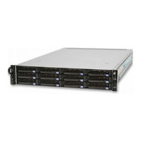
IBM Power Systems Series Manual (76 pages)
Serial-attached SCSI RAID enablement and cache battery pack
Brand:
IBM
| Category:
Server
| Size: 3.11 MB
Table of Contents
Table of Contents
5
Safety Notices
7
SAS RAID Enablement and Cache Battery Pack for the 8248-L4T, 8408-E8D, or 9109-RMD
13
Removing the 175 MB Cache RAID - Dual IOA Enablement Card from the 8248-L4T, 8408-E8D, or 9109-RMD
15
Installing the 175 MB Cache RAID - Dual IOA Enablement Card in the 8248-L4T, 8408-E8D, or 9109-RMD
21
Removing and Replacing the Cache Battery Pack for the 8248-L4T, 8408-E8D, or 9109-RMD
23
Common Procedures for Installable Features
31
Before You Begin
33
Identifying a Part
37
Control Panel Leds
37
Identifying a Failing Part in an AIX System or Logical Partition
38
Locating a Failing Part in an AIX System or Logical Partition
38
Activating the Indicator Light for the Failing Part
39
Deactivating the Failing-Part Indicator Light
39
Identifying a Failing Part in an IBM I System or Logical Partition
39
Activating the Failing-Part Indicator Light
39
Deactivating the Failing-Part Indicator Light
40
Identifying a Failing Part in a Linux System or Logical Partition
41
Locating a Failing Part in a Linux System or Logical Partition
41
Finding the Location Code of a Failing Part in a Linux System or Logical Partition
41
Activating the Indicator Light for the Failing Part
41
Deactivating the Failing-Part Indicator Light
41
Locating a Failing Part in a Virtual I/O Server System or Logical Partition
42
Identifying a Part by Using the Virtual I/O Server
42
Starting the System or Logical Partition
43
Starting a System that Is Not Managed by an HMC or an SDMC
43
Starting a System or Logical Partition by Using the HMC
44
Starting a System or Virtual Server by Using the SDMC
44
Stopping a System or Logical Partition
47
Stopping a System that Is Not Managed by an HMC or an SDMC
47
Stopping a System by Using the HMC
48
Stopping a System by Using the SDMC
49
Removing and Replacing Covers for the 8248-L4T, 8408-E8D, or 9109-RMD
51
Removing the Front Cover from the 8248-L4T, 8408-E8D, or 9109-RMD
51
Installing the Front Cover on the 8248-L4T, 8408-E8D, or 9109-RMD
51
Verifying the Installed Part
53
Verifying an Installed Feature or Replaced Part in an AIX System or Logical Partition
53
Verifying the Installed Part in an IBM I System or Logical Partition
55
Deactivating the Failing-Part Indicator Light
56
Verifying the Installed Part in a Linux System or Logical Partition
56
Verifying an Installed Part by Using Stand-Alone Diagnostics
57
Verifying the Installed Part by Using the HMC
58
Activating and Deactivating Leds by Using the HMC
59
Deactivating a System Attention LED or Partition LED by Using the HMC
59
Activating or Deactivating an Identify LED by Using the HMC
59
Viewing Serviceable Events by Using the HMC
59
Verifying the Installed Part by Using the SDMC
60
Activating and Deactivating Leds by Using the SDMC
61
Deactivating a System Attention LED or Partition LED by Using the SDMC
61
Activating or Deactivating an Identify LED by Using the SDMC
61
Viewing Serviceable Events by Using the SDMC
62
Verifying an Installed Part or Replaced Part on a System or Logical Partition by Using Virtual I/O Server Tools
62
Verifying the Installed Part by Using VIOS
62
Verify the Replacement Part by Using VIOS
62
Notices
65
Trademarks
66
Electronic Emission Notices
66
Class a Notices
66
Class B Notices
70
Terms and Conditions
73
IBM Power Systems Series Installing (56 pages)
Brand:
IBM
| Category:
Computer Hardware
| Size: 0.99 MB
Table of Contents
Table of Contents
3
Safety Notices
5
Installing the IBM Power System S922 (9009-22A and 9009-22G), IBM Power System H922 (9223-22H), or IBM Power System H922S (9223-22S)
15
Installing a Rack-Based Server
15
Prerequisite for Installing the Rack-Mounted Server
15
Completing Inventory for Your Server
15
Determining and Marking the Location in the Rack
16
Attaching the Mounting Hardware to the Rack
18
Installing the System into the Rack
21
Installing the Cable-Management Arm
23
Cabling the Server and Setting up a Console
26
Cabling the Server and Connecting Expansion Units
32
Completing the Server Setup
33
Setting up a Preinstalled Server
36
Notices
45
Accessibility Features for IBM Power Systems Servers
46
Privacy Policy Considerations
47
Trademarks
47
Electronic Emission Notices
48
Class a Notices
48
Class B Notices
51
Terms and Conditions
53
IBM Power Systems Series Manual (40 pages)
SAS subsystem for the servers
Brand:
IBM
| Category:
Storage
| Size: 6.14 MB
Table of Contents
Table of Contents
5
Safety Notices
7
SAS Subsystem for the 8202-E4C, 8202-E4D, 8205-E6C, or 8205-E6D
13
What's New in SAS Subsystem for the 8202-E4C, 8202-E4D, 8205-E6C, or 8205-E6D
13
SAS Architecture
13
SAS Subsystem Overview for the 8202-E4C, 8202-E4D, 8205-E6C, or 8205-E6D
13
SAS Storage Configurations
17
SAS Subsystem Base Configuration for the 8202-E4C, 8202-E4D, 8205-E6C, or 8205-E6D
18
SAS Base Subsystem with Two-Way Split Drive Backplane for the 8202-E4C, 8202-E4D, 8205-E6C, or 8205-E6D
19
SAS Dual-RAID Subsystem for the 8202-E4C, 8202-E4D, 8205-E6C, or 8205-E6D
21
SAS Dual-RAID Subsystem with Internal Drives for the 8202-E4C, 8202-E4D, 8205-E6C, or 8205-E6D
21
SAS Dual-RAID Subsystem with External Drives for the 8202-E4C, 8202-E4D, 8205-E6C, or 8205-E6D
23
SAS Subsystem Service Considerations for the 8202-E4C, 8202-E4D, 8205-E6C, or 8205-E6D
25
Service Considerations for the Cache Battery Pack
26
Problem Determination and Recovery
28
Notices
29
Trademarks
30
Electronic Emission Notices
30
Class a Notices
30
Class B Notices
34
Terms and Conditions
37
IBM Power Systems Series Manual (46 pages)
Cabling your server
Brand:
IBM
| Category:
Server
| Size: 2.19 MB
Table of Contents
Table of Contents
5
Safety Notices
7
Cabling Your Server
13
Cabling the 8202-E4B or 8202-E4C
14
Cabling the 8205-E6B or 8205-E6C
17
Cabling the 8231-E2B, 8231-E1C, or 8231-E2C
21
Cabling the 8233-E8B
25
Cabling the 8236-E8C
29
Notices
35
Trademarks
36
Electronic Emission Notices
36
Class a Notices
36
Class B Notices
40
Terms and Conditions
43
Advertisement
Related Products
IBM @server iSeries
IBM @server xSeries 450
IBM SC34-7012-01
IBM SG24-4576-00
IBM SA38-0511
IBM Power System S821LC
IBM Power Systems S812LC 8348-21C
IBM Power System S814
IBM SA41-5078
IBM SA2
IBM Categories
Server
Desktop
Storage
Laptop
Monitor
More IBM Manuals
Login
Sign In
OR
Sign in with Facebook
Sign in with Google
Upload manual
Upload from disk
Upload from URL