Sign In
Upload
Manuals
Brands
Festo Manuals
Terminal Block
VIFB-02-1/8-10
Festo VIFB-02-1/8-10 Manuals
Manuals and User Guides for Festo VIFB-02-1/8-10. We have
3
Festo VIFB-02-1/8-10 manuals available for free PDF download: Manual
Festo VIFB-02-1/8-10 Manual (160 pages)
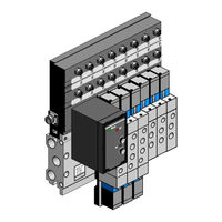
Valve Terminal/Valve Sensor Terminal with Field Bus Connection, Field bus protocol: PROFIBUS DP 12 MBaud
Brand:
Festo
| Category:
Touch terminals
| Size: 1.74 MB
Table of Contents
Table of Contents
5
Kapitel 1 USER INSTRUCTIONS
7
Important User Instructions
9
Kapitel 2 SYSTEM STRUCTURE
13
2. System Structure
14
System Structure
15
Valve Terminal
15
Valve Sensor Terminal
16
Valve Terminal/Valve Sensor Terminal in the Control System
17
Kapitel 3 TECHNICAL DESCRIPTION
21
3. Technical Description
22
Structure
23
Technical Description
23
Valve Sensor Terminal
25
Function
28
Notes on Function Summary
29
General
30
Technical Specifications
30
Electronic Components
31
Field Bus
33
Pneumatic Components
34
Sub-Base
34
Kapitel 4 INSTALLATION
39
4. Installation
40
Fitting the Valve Terminal/Valve Sensor Terminal
41
Installation
41
Installing the Pneumatic Components
43
General
43
Laying the Tubing
43
Preparing the Sub-Base
44
Connecting the Sub-Base
45
Connecting the Valves
46
Checking the Valve Functions
49
Manual Override
49
Installing the Electronic Components
54
Opening and Closing the Field Bus Node
55
Configuring the Valve Terminal/Valve Sensor Terminal
56
Setting the Station Number and Operating Mode
57
Address Selector Switch
58
Field Bus Baud Rate and Field Bus Length
61
Connecting the Cables to the Plugs/Sockets
62
Connecting the Valve Terminal/Valve Sensor Terminal
62
Operating Voltage Connection
64
Connecting the PROFIBUS DP Interface
69
Screening Connection
70
Kapitel 5 COMMISSIONING
79
5. Commissioning
80
Commissioning
81
Configuring the PLC
81
Switching on the Operating Voltage
82
Siemens
83
General
83
Commissioning Tips
84
FREEZE and SYNC
85
Module Consistency
87
Status Bits
87
Sequence of Configuration Entries
88
Station Selection with COM ET200 Windows/Com PROFIBUS
93
Configuration COM ET200 Windows V2.X/Com PROFIBUS
95
Configuration with STEP 7 V2.X or
101
NCM S7-PROFIBUS V2.X
101
NCM S7-PROFIBUS V2.X
104
Addressing the Inputs and Outputs
105
Valve Terminal
105
Valve Sensor Terminal
107
Addressing Examples
110
General Dp-Master
112
Status Bits
112
Module Consistency
113
Sequence of Configuration Entries
113
Bus Start
114
Send Parametrizing Data
115
Send Configuration Data
117
Request Diagnostic Information
118
Bus Parameter/Reaction Times
121
Summary of Implemented Functions and Service Access Points (SAP)
121
FREEZE and SYNC
122
Device Master File (GSD)
124
Examples
126
Kapitel 6 DIAGNOSTICS and ERROR TREATMENT
127
6. Diagnostics and Error Treatment
128
Summary of Diagnostic Possibilities
129
Led Displays
130
Field Bus Node
130
Valves
132
Inputs and Additional Outputs
133
Test Routines
134
Display Configuration Data
136
Status Bits
137
Position of Status Bits
138
Diagnosis Via Profibus-Dp (Dp-Standard)
140
Diagnostic Words
140
Diagnostic Possibilities Via PROFIBUS-DP
141
Summary of Diagnostic Bytes
142
Structure of Station Status 1
142
(Only Valve-Terminal Related Bits)
143
Structure of Station Status 2
143
(Contents Depends on Master)
143
Structure of Device-Related Diagnosis 1
144
Diagnosis Via Profibus-Dp (General Dp-Master)
145
General
145
Diagnostic Information
146
Error Treatment
149
Reaction to Faults in the Control System
149
General DP-Master
150
Short Circuit/Overload at an Output Module
151
Index
153
Advertisement
Festo VIFB-02-1/8-10 Manual (133 pages)
Valve terminal/valve sensor terminal with field bus connection
Brand:
Festo
| Category:
Terminal Block
| Size: 6.59 MB
Table of Contents
3. Technical Description
19
Technical Description
18
Table of Contents
19
Structure
20
Valve Sensor Terminal
21
Function
25
Technical Specifications
27
Electronic Components
28
Field Bus
30
Pneumatic Components
31
Valve Sensor Terminal
36
Connection Block
38
4.2 Installing the Pneumatic Components
41
Installing the Pneumatic Components
42
Laying the Hoses
42
Preparing the Connection Block
43
Connecting the Connection Block
44
Connecting the Valves
45
Solenoid Valve (5/2-Way)
46
Solenoid Pulse Valve (5/2-Way) and Solenoid MID-Position Valve (5/3-Way)
47
Checking the Valve Functions
48
Manual Overrride
48
Designs of Manual Override
49
Testing
50
Locking the Manual Override
52
Vifb1
54
4.3 Installing the Electronic Components
55
Valve Sensor Terminal
55
Installing the Electronic Components
56
Opening and Closing the Field Bus Node
57
Configuring the Valve Terminal/Valve Sensor Terminal
58
Address Selector Switch
59
Setting the Field Bus Address
59
Dual In-Line Switch (DIL Switch)
61
Setting the Field Bus Baud Rate
62
Setting the Field Bus Protocol
62
Connecting the Valve Terminal/Valve Sensor Terminal
63
General
63
24 V Operating Voltage Connection
65
Applying the 24 V Operating Voltage
66
Field Bus Interface
69
Connecting the Field Bus Interface
70
Field Bus Cable
70
Fitting the Terminating Resistor
73
Outputs and Valve Locations
75
Additional Outputs
76
Connection Assignment of Additional Outputs
77
Inputs
78
Connection Assignment of Inputs
79
Circuitry
80
5. Commissioning
83
Commissioning
84
Configuring the PLC
84
Festo
85
Klöckner-Moeller
86
Siemens
86
Switching on the Operating Voltage
90
Addressing the Inputs and Outputs
91
Valve Locations
91
Valve Terminal
91
Valve Locations, Inputs and Additional Outputs
93
Valve Sensor Terminal
93
Status Bits
96
Festo
97
Manufacturer-Specific Features
97
Klöckner-Moeller
98
Siemens
102
6. Diagnostic and Error Treatment
108
Field Bus Node
109
LED Displays
109
Valves
111
Inputs and Additional Outputs
112
Diagnostic Byte
113
Festo
113
Klöckner-Moeller
116
Siemens
118
Testing the Valves and Additional Outputs
121
Control System
123
Reaction During Faults
123
Short Circuit/Overload at the Additional Output
124
System Structure
131
Valve Terminal
132
Festo VIFB-02-1/8-10 Manual (123 pages)
Valve Terminal/Valve Sensor Terminal with Field Bus Connection
Brand:
Festo
| Category:
Touch terminals
| Size: 0.74 MB
Table of Contents
2. System Structure
11
System Structure
12
Valve Terminal
12
Valve Sensor Terminal
13
Valve Terminal/Valve Sensor Terminal in the Control System
14
3. Technical Description
19
Table of Contents
19
Technical Description
20
Structure
20
Valve Terminal
20
Valve Sensor Terminal
22
Function
25
Explanation on Function Summary
26
Technical Specifications
27
General
27
Electronic Components
28
RIO Link
30
Pneumatic Components
31
Connection Block
31
Valves
36
4.2 Installing the Pneumatic Components
41
Installing the Pneumatic Components
42
Laying the Hoses
43
General
43
Preparing the Connection Block
44
Connecting the Connection Block
45
Connecting the Valves
46
Solenoid Valve (5/2-Way)
47
Solenoid Pulse Valve (5/2-Way) and Solenoid MID-Position Valve (5/3-Way)
48
Checking the Valve Functions
49
Manual Overrride
49
Designs of Manual Override
50
Testing
51
Locking the Manual Override
53
4.3 Installing the Electronic Components
55
Installing the Electronic Components
56
Opening and Closing the RIO Node
58
Configuring the Valve Terminal/Valve Sensor Terminal
59
Address Selector Switch
60
Setting the RIO Address
60
Setting the RIO Baud Rate
63
Connecting the Valve Terminal/Valve Sensor Terminal
64
Connetcting the Cables to the Plugs/Sockets
64
24 V Operating Voltage Connection
66
Applying the 24V Operating Voltage
69
RIO Interface
72
RIO Cable
73
Connecting the RIO Interface
73
Fitting the Terminating Resistor
75
Outputs of Valve Locations
77
Additional Outputs
77
Pin Assignment Od Additional Outputs
78
Inputs
79
Pin Assignment of Sockets
80
Circuitry Examples
81
5. Commissioning
85
Commissioning
86
Configuring the Programmable Controller
86
Allen-Bradley
87
Switching on the Operating Voltage
88
Addressing the Inputs and Outputs
89
Valve Terminal
89
Valve Locations
89
Valve Sensor Terminal
91
Valve Locations, Inputs and Additional Outputs
91
Status Bits
94
Manufacturer-Specific Features
95
Allen-Bradley
95
6. Diagnosis and Error Treatment
105
Diagnosis and Error Treatment
106
LED Displays
106
RIO Node
106
Valves
108
Inputs and Additional Outputs
109
Testing the Valves and Additional
110
Diagnosis
110
Outputs
110
Reaction During Faults
114
Short Circuit/Overload at the Additional
115
Advertisement
Advertisement
Related Products
Festo VIFB-02-1/8-4
Festo VIFB-02-1/8-6
Festo VIFB-02-1/8-8
Festo VIFB-02-1/8-12
Festo VIFB-02-1/8-14
Festo VIFB-02-1/8-16
Festo VIFB-02-1/4-10
Festo VIFB-02-1/4-16
Festo VIFB-02-1/4-6
Festo VIFB-02-1/4-4
Festo Categories
Industrial Equipment
Control Unit
Controller
Touch terminals
DC Drives
More Festo Manuals
Login
Sign In
OR
Sign in with Facebook
Sign in with Google
Upload manual
Upload from disk
Upload from URL