
Related Manuals for Festo VIFB-02 Series


Summary of Contents for Festo VIFB-02 Series
- Page 1 Valve Terminal/Valve Sensor Terminal with Field Bus Connection VIFB8-/IIFB8-02-... Manual Fieldbus protocol: Allen-Bradley Remote I/O link 9706...
- Page 2 Festo, Dept. PV-IDM Type setting: DUCOM Edition 9706 © (Festo AG & Co., 73726 Esslingen, Federal Republic of germany, 1997) The copying, distribution and utilization of this document as well as the communication of its contents to others without expressed authoriza- tion is prohibited.
- Page 3 VIFB8 – 02 Order no.: 151 763 Title: MANUAL Designation: P.BE-VIFB8-02-GB PLC-2 is a registered trademark of Allen-Bradley Company Inc. PLC-3 is a registered trademark of Allen-Bradley Company Inc. PLC-5 is a trademark of Allen-Bradley Company Inc. SLC-500 is a trademark of Allen-Bradley Company Inc. 9706...
- Page 4 VIFB8 – 02 Contents Contents Chapter 1 IMPORTANT USER INSTRUCTIONS Chapter 2 SYSTEM STRUCTURE Chapter 3 TECHNICAL DESCRIPTION Chapter 4 INSTALLATION 4.1 Fitting the valve terminal/ valve sensor terminal ....4-1 4.2 Installing the pneumatic components .
- Page 5 VIFB8 – 02 9706...
- Page 6 VIFB8 – 02 1. Important user instructions 1. IMPORTANT USER INSTRUCTIONS 9706...
- Page 7 VIFB8 – 02 1. Important user instructions Contents IMPORTANT USER INSTRUCTIONS..1-3 9706...
- Page 8 VIFB8 – 02 1. Important user instructions IMPORTANT USER INSTRUCTIONS This description contains instructions on the possible dangers which can occur with the valve terminal/valve sensor terminal. A distinction is made between the following in- structions: WARNING Indicates a potentially hazardous situation, which, if not avoided, could result in death or serious injury.
- Page 9 Allen-Bradley RIO link. PLEASE NOTE This product incorporates technology which is licensed by Allen-Bradley Company Inc.. Allen-Bradley does not technically approve, nor does it warrant or support this product. All warranty and support for this product is provided by Festo. 9706...
- Page 10 VIFB8 – 02 2. System structure 2. SYSTEM STRUCTURE 9706...
- Page 11 VIFB8 – 02 2. System structure Contents SYSTEM STRUCTURE....2-3 Valve terminal ......2-3 Valve sensor terminal .
-
Page 12: System Structure
2. System structure SYSTEM STRUCTURE Valve terminal Festo offers a solution to automation problems at the machine level in the form of the valve termi- nal. Solenoid valves, solenoid pulse valves etc. are ready fitted onto a connection block and have already been tested. -
Page 13: Valve Sensor Terminal
Valve sensor terminal Complex automation tasks require the use of sensors for which Festo offers the valve sensor terminal. Solenoid valves, solenoid pulse valves etc. are fitted onto a connection block and have already been tested; two sensors per valve can be connected on site. -
Page 14: Valve Terminal/Valve Sensor Terminal In The Control System
VIFB8 – 02 2. System structure Valve terminal/valve sensor terminal in the control system The valve terminal/valve sensor terminals are participants in the Allen-Bradley RIO link. They can be connected to RIO scanner ports of the following automation systems: Programmable controller RIO scanner family ®... - Page 15 VIFB8 – 02 2. System structure Allen-Bradley 1771 I/O chassis A-B PLC-3 VIFB8-02-... Power unit 24 V = Actuator IIFB8-02-... Sensor Sensor Actuator Fig. 2/4: System structure of Allen-Bradley RIO link with valve terminal valve sensor terminal 9706...
- Page 16 VIFB8 – 02 2. System structure The Allen-Bradley RIO link creates data com- munication between the controller and the slaves (e.g. valve terminal/valve sensor terminal or remote I/O) distributed throughout the system. Baud rates up to 57.6K, 115.2K or 230.4 K Baud can be set.
- Page 17 VIFB8 – 02 2. System structure 9706...
- Page 18 VIFB8 – 02 3. Technical description 3. TECHNICAL DESCRIPTION 9706...
-
Page 19: Table Of Contents
VIFB8 – 02 3. Technical description Contents TECHNICAL DESCRIPTION ... . . 3-3 Structure......3-3 Valve terminal . -
Page 20: Technical Description
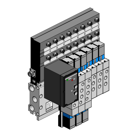
VIFB8 – 02 3. Technical description TECHNICAL DESCRIPTION Structure Valve terminal The valve terminal consists of the following com- ponents: Figure Components RIO node Valve terminal base unit consisting of: • Valve coupling unit (upper part) • Connection block (lower part) Valve locations for •... - Page 21 VIFB8 – 02 3. Technical description The following operation and display elements are to be found on the components of the valve ter- minal: 1 Valve terminal inscription field 2 Red LED (Power) 3 Green LED (Bus) 4 Operating voltage connection 5 RIO interface 6 Type plate 7 Valve location inscription field (per valve solenoid coil)
-
Page 22: Valve Sensor Terminal
VIFB8 – 02 3. Technical description Valve sensor terminal The valve sensor terminal consists of the follow- ing components: Figure Components RIO node Valve sensor terminal base unit consisting of: • Valve sensor coupling unit (upper part) • Connection block (lower part) Valve locations for •... - Page 23 VIFB8 – 02 3. Technical description The following operation and display elements are to be found on the components of the valve sen- sor terminal: 1 Connections for additional outputs 2 Common fuse for inputs 3 Valve sensor terminal inscription field 4 Red LED (Power) 5 Green LED (Bus) 6 Operating voltage connection...
- Page 24 VIFB8 – 02 3. Technical description The composition of the type plate is shown in Fig. 3/5 using the valve sensor terminal as an example. The type plate is situated below the RIO node and contains the following specifica- tions: Type designation of base unit ⁄...
-
Page 25: Function
VIFB8 – 02 3. Technical description Function The valve terminal or valve sensor terminal should be placed in the immediate vicinity of the processing unit. Connection to the control level is made via the RIO link which operates on the master-slave principle. -
Page 26: Explanation On Function Summary
VIFB8 – 02 3. Technical description Explanation of the function summary The RIO node controls the following functions: • The connection of the valve terminal/valve sensor terminal to the A-B RIO scanner of the programmable controller and to further RIO slaves via the RIO interface. -
Page 27: Technical Specifications
VIFB8 – 02 3. Technical description Technical specifications General Protection class IP 65 (as per DIN 40050) Temperature at • operation C . . . +50 • storage/transport C . . . +60 ⁄ Dimensions (LxWxH) Specifications of the " when base unit is design are given in round fully fitted... -
Page 28: Electronic Components
VIFB8 – 02 3. Technical description Electronic components Operating voltage Electronic components and inputs (Pin 1 – Operating voltage connection) • Rated value DC 24 V (protection against incorrect polarity) • Tolerance ± 25 % (DC18 V . . . 30 V) •... - Page 29 VIFB8 – 02 3. Technical description Electromagnetic compatibility (EMC): Resistance to interference • tested as per EN 50082-2 Limit value class A *) Spark suppression • tested as per EN 55011 Protection against electric by means of PELV shock (protection against power units (protected direct and indirect contact as extra low voltage)
-
Page 30: Rio Link
VIFB8 – 02 3. Technical description RIO link Transmission type master/slave Protocol Allen-Bradley RIO Baud rate 57.6 kBaud 115.2 kBaud 230.4 kBaud Cable type Belden 9463 shielded twisted-pair Cable length 3.3 km at 57.6 kBaud 1.6 km at 115.2 kBaud 0.8 km at 230.4 kBaud Terminators refer to A-B publications... -
Page 31: Pneumatic Components
VIFB8 – 02 3. Technical description Pneumatic components • filtered or filtered Air quality and dried compressed air • lubricated or unlubricated compressed air Filter fineness (standard) • Poppet valve 40 µm • Spool valve 40 µm Pressure • Operating pressure range 2 bar ... - Page 32 VIFB8 – 02 3. Technical description Please unfold for page 3-16 Please unfold for page 3-16 9706 3-15...
- Page 33 VIFB8 – 02 3. Technical description Technical specifications of valves Designation Size Switching symbol Construction Pilot air Manual override Lubrication Fastening with 2 slotted Type Form Basic Option head screws setting (as (conversion at factory) necessary) MVH-5-1/4 B-VI 1/4" M4x55 without Poppet valve Single spindle with...
- Page 34 VIFB8 – 02 3. Technical description Size Pressure Flow Times Operating Pilot pressure Size of connection Nominal Rated flow Valve switching Reaction pressure with size Switch position times time calculation Auxiliary (Pneumatic 2 and 4 12 and 14 2 or 1 3 or 4 ON at OFF at...
- Page 35 VIFB8 – 02 3. Technical description Please unfold for page 3-17 Please unfold for page 3-17 3-18 9706...
-
Page 36: Valves
VIFB8 – 02 4. Installation 4.1 FITTING THE VALVE TERMINAL/ VALVE SENSOR TERMINAL 9706... - Page 37 VIFB8 – 02 4. Installation Contents FITTING THE VALVE TERMINAL/ VALVE SENSOR TERMINAL ... . 4-3 9706...
- Page 38 VIFB8 – 02 4. Installation FITTING THE VALVE TERMINAL/VALVE SENSOR TERMINAL Before fitting the valve terminal/valve sensor ter- minal please see that there is sufficient space to the left and/or right of the connection block for fitting the hoses and, if necessary, the silencers. There are 4 through holes on the right and left- hand edges of the connection block for fastening the valve terminal/valve sensor terminal (see fol-...
- Page 39 VIFB8 – 02 4. Installation The following procedure should be adopted: 1. Bore four holes in the mounting surface. The distance between the holes depends on the type of valve terminal/valve sensor terminal ⁄ used (specifications of the " design are given in round brackets).
- Page 40 VIFB8 – 02 4. Installation 4.2 INSTALLING THE PNEUMATIC COMPONENTS 9706...
- Page 41 VIFB8 – 02 4. Installation Contents INSTALLING THE PNEUMATIC COMPONENTS ......4-7 Laying the hoses ..... . 4-8 General .
-
Page 42: Installing The Pneumatic Components
VIFB8 – 02 4. Installation INSTALLING THE PNEUMATIC COMPONENTS WARNING Before installation or maintenance work is carried out the following must be switched off: • the operating voltage for electronic components and/or inputs. • the operating voltage supply. • the compressed air. You thereby avoid: •... -
Page 43: Laying The Hoses
VIFB8 – 02 4. Installation Laying the hoses PLEASE NOTE • A suitable seal should be placed under each screw connection or each silencer. • If elbow connectors or multiple distributors are used the air flow will usually be reduced. General •... -
Page 44: Preparing The Connection Block
VIFB8 – 02 4. Installation Preparing the connection block Connections for common lines are provided on both sides of the connection block. The common lines can therefore be fitted either on the right or the left, depending on individual requirements. To increase the air flow we recommend that the lines for compressed air supply and ventilation be connected on both sides in the following... -
Page 45: Connecting The Connection Block
VIFB8 – 02 4. Installation Connecting the connection block The screw connectors or silencers should be fitted with the appropriate seals as indicated in the table below. The hoses should then be fitted into place. Pilot exhaust Pilot exhaust 5 or 3 Exhaust 3 or 5 Exhaust... -
Page 46: Connecting The Valves
VIFB8 – 02 4. Installation Connecting the valves PLEASE NOTE • The non-reserved or free valve locations should be protected with a cover plate. • If one of the fitted valves is not used, connections 2 and 4 as well as 14 and, if necessary, 12 must be covered with blind plugs. -
Page 47: Solenoid Valve (5/2-Way)
VIFB8 – 02 4. Installation Solenoid valve (5/2-way) MVH-5-1/4-B-VI MVH-5-1/4- -B-VI MVH-5-1/8-B-VI MVH-5-1/8- -B-VI MVH-5-1/4-S-B-VI MVH-5-1/4- -S-B-VI MVH-5-1/8-S-B-VI MVH-5-1/8- -S-B-VI Line Connection code Size Connection (ISO 5599) (ISO 228) ⁄ ⁄ Work air Screw connector or multiple distributor ⁄ ⁄ Auxiliary pilot Only with "S valves"... -
Page 48: Solenoid Pulse Valve (5/2-Way) And Solenoid Mid-Position Valve (5/3-Way)
VIFB8 – 02 4. Installation Solenoid pulse valve (5/2-way) and Solenoid mid-position valve (5/3-way) Auxiliary pilot air – only "S valve" – Work air Auxiliary pilot air – only "S valve" – Line Connection Size of Connection code connection (ISO 5599) (ISO 228) ⁄... -
Page 49: Checking The Valve Functions
VIFB8 – 02 4. Installation Checking the valve functions Manual override WARNING The manual override suppresses the effect of the electric signal. Possible consequences: • uncontrolled, unintended movement of the actuators. • the installed EMERGENCY STOP circuit has no effect. The manual override is mainly used when com- missioning the pneumatic components to test the function of the valve or valve/cylinder combina-... -
Page 50: Designs Of Manual Override
VIFB8 – 02 4. Installation Pilot valve Manual override Base valve Manual override Pilot valve Fig. 4/7: Position of the manual override Designs of manual override The manual override has been designed so that it can be used as follows: Manual override design Method of operation Manual operation with... -
Page 51: Testing
VIFB8 – 02 4. Installation Testing 1. Switch on the compressed air supply. 2. Check the function and effect of each indivi- dual valve as follows. If the valve does not function correctly see Fig. 4/11. • Manual override with automatic reset: Operating the manual override Reaction of valve or of processor... - Page 52 VIFB8 – 02 4. Installation • Manual override with stop: Operating the manual override Reaction of valve or of processor The valve or processor • switches Insert screwdriver in groove of plunger. Press plunger as far as it will go and turn it to the right.
-
Page 53: Locking The Manual Override
VIFB8 – 02 4. Installation Incorrect functioning: When the compressed air supply is switched on or during the subsequent test of the valves, the following is known about the operating status of the pneumatic system: Operating status Valve position Error treatment of pneumatic system after switching off compressed air supply... - Page 54 VIFB8 – 02 4. Installation 4.3 INSTALLING THE ELECTRONIC COMPONENTS 4-19 9706...
- Page 55 VIFB8 – 02 4. Installation Contents INSTALLING THE ELECTRONIC COMPONENTS ..... . . 4-21 Opening and closing the RIO node..4-23 Configuring the valve terminal/ valve sensor terminal .
-
Page 56: Installing The Electronic Components
VIFB8 – 02 4. Installation INSTALLING THE ELECTRONIC COMPONENTS WARNING Before installation or maintenance work is carried out the following must be switched off: • the operating voltage for electronic components and/or inputs. • the operating voltage for outputs. • the compressed air supply. - Page 57 – Hold Last State – Processor Restart Lockout CAUTION For security applications: With Festo valve terminals/valve sensor termi- nals, the functions "Hold Last State" or "Processor Restart Lockout" must be realized by using double solenoid valves. The necessary pre-settings and the connections to the electronic components are described in this chapter.
-
Page 58: Opening And Closing The Rio Node
VIFB8 – 02 4. Installation Opening and closing the RIO node CAUTION Before the RIO node is opened, the operating voltage of the following must be switched off: • electronic components and or inputs • outputs The following connection and display elements are situated on the cover of the RIO node: POWER Green LED... -
Page 59: Configuring The Valve Terminal/Valve Sensor Terminal
VIFB8 – 02 4. Installation Configuring the valve terminal/valve sensor terminal There are two PC boards in the RIO node. Board 1 contains the red LED; board 2 contains a green LED and a switch for setting the address and baud rate. DIL-switch Red LED (baud rate) -
Page 60: Address Selector Switch
VIFB8 – 02 4. Installation Address selector switch The RIO address of the valve terminal/valve sen- sor terminal can be set with the two address se- lector switches on board 2. The switches are numbered from 0 ... 9. The arrow on the address selector switches indicates the tens and units fig- ure of the RIO address which has been set. - Page 61 VIFB8 – 02 4. Installation Possible RIO addresses: PLEASE NOTE Do not use the following chart to set the ad- dress switches. Please go to chapter 5. Commissioning and refer to the tables, "Addressing facilites" for setting the switches. A-B programmable I/O rack no.
- Page 62 VIFB8 – 02 4. Installation Example: UNITS Example 1 RIO address set: 05 TENS UNITS Example 2 RIO address set: 38 TENS Fig. 4/16: Example of RIO addresses set 4-27 9706...
-
Page 63: Setting The Rio Baud Rate
VIFB8 – 02 4. Installation Setting the RIO baud rate PLEASE NOTE The RIO baud rate should be set on the valve terminal/valve sensor terminal so that it agrees with the setting on the programmable control- ler (master). The following A-B specific functions are not implemented: –... -
Page 64: Connecting The Valve Terminal/Valve Sensor Terminal
VIFB8 – 02 4. Installation Connecting the valve terminal/valve sensor terminal Connecting the cables to the plug/sockets PLEASE NOTE If one of the plugs is not used, it should be sealed with a protective cap (protection class IP65). 1. Open the plugs/sockets as follows (see following diagram) •... - Page 65 VIFB8 – 02 4. Installation 2. Unscrew the strain relief part at the rear of the housing. Insert the cable as follows (see diagram): Cable diameter: • for power supply socket: 6.5 mm ... 8.0 mm • for sensor plug: 4.0 mm ...
-
Page 66: 24 V Operating Voltage Connection
VIFB8 – 02 4. Installation 5. Connect the ends of the conductors. 6. Replace the connection part onto the housing of the plug/socket. Pull the cable back so that it is not looped around inside the bushing. 7. Close the plug as follows: •... - Page 67 Remark: Protection against electric shock (protection ag- tainst direct and indirect contact) is guarantee on Festo valve terminals by the use of PELV power units in accordance with EN 60204-1/IEC 204. The valve terminals must be earthed in order to ensure function (e.g.
- Page 68 VIFB8 – 02 4. Installation PLEASE NOTE The electronic components and the inputs show a greater tolerance range of the 24V DC operating voltage than the outputs. Under cer- tain circumstances this can cause the electro- nic components to indicate the switching sta- tus of the outputs, although the latter are not in the switched position (operating voltage of the outputs outside tolerance range).
-
Page 69: Applying The 24V Operating Voltage
VIFB8 – 02 4. Installation Applying the 24V operating voltage CAUTION Please observe the polarity when the opera- ting voltage is applied. Connect the earthing to pin 4, PE. The following diagram shows the pin assignment of the operating voltage connection. A suitable 24V DC supply should be connected via the mains connection socket (see Chapter 3, Techni- cal specifications). - Page 70 VIFB8 – 02 4. Installation Recommendation • Protect the 24 V DC supply to the outputs with a fuse. • The 24 V DC output supply should be con- nected to the EMERGENCY STOP circuit (see figure below). The valves can then be switched off in an emer- gency.
- Page 71 VIFB8 – 02 4. Installation Current consumption of electronic components (field bus node) and inputs (pin 1, 24 V ± 25 %) VIFB-/IIFB-02-1/x-4 VIFB-/IIFB-02-1/x-6 VIFB-/IIFB-02-1/x-8 VIFB-/IIFB-02-1/x-10 0.200 A VIFB-/IIFB-02-1/x-12 VIFB-/IIFB-02-1/x-14 Number of sensor inputs ∑ assigned simultaneously: _____x0.010 A ∑ Sensor supply: _____x_____ A (see manufacturer specifications)
-
Page 72: Rio Interface
VIFB8 – 02 4. Installation RIO interface There are two plugs on the RIO node for con- necting the valve terminal/valve sensor terminal to the RIO. One of these plugs is intended for the incoming RIO cable, the other is for the con- tinuing RIO cable. -
Page 73: Rio Cable
VIFB8 – 02 4. Installation RIO cable A shielded twisted-pair cable (Belden 9463) should be used as the RIO cable. The distance and the RIO baud rate set should be taken into account as shown in the diagram below. Connecting the RIO interface CAUTION Please observe the polarity when the RIO cables are connected. - Page 74 VIFB8 – 02 4. Installation PLEASE NOTE Some products within each programmable controller family are limited to less terminals or are not capable of all three baud rates. Consult A-B product literature for specificati- ons. Programmab Scanner Max. no. of Terminating Selected Max.
-
Page 75: Fitting The Terminating Resistor
VIFB8 – 02 4. Installation Fitting the terminating resistor PLEASE NOTE If a terminating resistor is used, one of the RIO plugs on the last valve/installation termi- nal of a RIO line is not assigned. Protection in accordance with protection class IP65 as per DIN 40050 is therefore no longer guaranteed. - Page 76 VIFB8 – 02 4. Installation Proceed as follows: 1. Connect the wires of the resistor together with those of the incoming RIO cable between the wires S+ (pin 1) and S- (pin 3) of the sen- sor/RIO cable socket (see following figure). To guarantee more reliable contact, we re- commend that the wires of the resistor and those of the incoming RIO cable be crimped...
-
Page 77: Outputs Of Valve Locations
VIFB8 – 02 4. Installation Outputs of valve locations The outputs for the valves correspond to the valve solenoid coils. They can only be used in the intended form. In general the following applies: • Outputs are not short-circuit protected •... -
Page 78: Pin Assignment Od Additional Outputs
VIFB8 – 02 4. Installation Pin assignment of additional outputs Socket free free O 0.00 O0.00 O0.01 free free O 0.01 Fig. 4/28: Pin assignment of sockets with additional outputs 4-43 9706... -
Page 79: Inputs
VIFB8 – 02 4. Installation Inputs There are two inputs for each valve location on the valve sensor coupling unit of the valve sen- sor terminal. There are two additional inputs ab- ove the RIO node. The inputs have positive logic (PNP inputs). -
Page 80: Pin Assignment Of Sockets
VIFB8 – 02 4. Installation Pin assignment of sockets The following diagram shows the pin assignment of all the inputs in socket form using inputs I0.00 and I0.01 as examples. Input Pin assignment Internal Explanation socket of sockets connection of pins Bridge between pins 2 and 4 I 0.00... -
Page 81: Circuitry Examples
VIFB8 – 02 4. Installation Circuitry examples Recommendation: If sensors are required, e.g. for a valve-cylinder combination, for interrogating limit switches, the inputs above the relevant valve should be used (clearer overview of the system). Examples Valve-cylinder combination with interrogation of limit switches via sensors. - Page 82 VIFB8 – 02 4. Installation • Example 2 Connecting e.g. two sensors with one plug (sockets on lower row). Sensor 1 Pin 1 24 V Pin 3 Pin 4 I0.08 1 2 4 3 Sensor 2 Pin 1 24 V Pin 3 Pin 4 I0.09...
- Page 83 VIFB8 – 02 4. Installation 4-48 9706...
- Page 84 VIFB8 – 02 5. Commissioning 5. COMMISSIONING 9706...
- Page 85 VIFB8 – 02 5. Commissioning Contents COMMISSIONING..... . 5-3 Configuring the programmable controller ......5-3 Allen-Bradley .
-
Page 86: Commissioning
VIFB8 – 02 5. Commissioning COMMISSIONING Configuring the programmable controller Before commissioning or programming, the user should compile a configuration list of the con- nected RIO slaves. On the basis of this list he can: • make a comparison between the ACTUAL and NOMINAL configurations in order to eli- minate connection faults. -
Page 87: Allen-Bradley
VIFB8 – 02 5. Commissioning Allen-Bradley If the valve terminal/valve sensor terminal is used on the Allen-Bradley RIO link the following must be observed: • Configuration The valve terminal/valve sensor terminal re- acts on the Allen-Bradley RIO link like a re- mote I/O block from Allen-Bradley. -
Page 88: Switching On The Operating Voltage
VIFB8 – 02 5. Commissioning Switching on the operating voltage Please note: The user should also consult the switching on instructions in the A-B programmable control- ler manual. When the controller is switched on, it may auto- matically make a comparison between the AC- TUAL and NOMINAL configurations. -
Page 89: Addressing The Inputs And Outputs
The designation of these outputs is noted on the valve terminal and is composed as follows: Festo designation for Output O 1 . 05 Bit-no. in output word Output word no. Output Fig. 5/1: Composition of Festo designation for outputs 9706... - Page 90 VIFB8 – 02 5. Commissioning The assignment of the outputs to the relevant valve location is shown in the diagram below. Outputs of the valve locations 0.00 0.02 0.04 0.06 0.08 0.10 0.12 0.14 1.00 1.02 Valve locations 0.01 0.03 0.05 0.07 0.09...
-
Page 91: Valve Sensor Terminal
Festo-designation for Input or Output O 0 . 03 I 1 . 05 Bit-no. input/output word Input/output word no. Input or output Fig. 5/4: Composition of Festo designation for inputs/outputs 9706... - Page 92 VIFB8 – 02 5. Commissioning The assignment of the inputs/outputs to the rele- vant valve location or additional input/output is shown in the diagram below. Inputs above Additional outputs Additional inputs the valve above the RIO node above the RIO node locations (O0.00 and O0.01) (I0.00 and I0.01)
- Page 93 VIFB8 – 02 5. Commissioning Example 1: Addressing and activating valves and additional outputs (SA0 and SA1). Valve Valve Festo Remarks location type designation con- tents single O0.06 Valve solenoid coil active solenoid O0.07 Output not evaluated double O1.04 Upper valve solenoid coil not active solenoid O1.05...
-
Page 94: Status Bits
Valve/ I1.14 I011/14 0 or 1 Meaning sensor I1.15 I011/15 terminal Chap. 6 * Example of designation for address 4 on the Festo terminal (I/O rack number 1, first 1/4 rack) Fig. 5/8: Addressing and reading status bit 5-11 9706... -
Page 95: Manufacturer-Specific Features
VIFB8 – 02 5. Commissioning Manufacturer-specific features Allen-Bradley The inputs/outputs of the valve terminal and valve sensor terminal are addressed like a quar- ter rack RIO from Allen-Bradley. The addressing of the valve terminal/valve sen- sor terminal in the Allen-Bradley RIO link de- pends on the Allen-Bradley programmable con- troller used. - Page 96 VIFB8 – 02 5. Commissioning Example 1 Output addresses of a valve terminal. Festo valve terminal Valve Output Address 4 Address 5 location Designator A-B O0.00 O010/00 O012/00 O0.01 O010/01 O012/01 O0.02 O010/02 O012/02 O0.03 O010/03 O012/03 O0.04 O010/04 O012/04 O0.05...
- Page 97 VIFB8 – 02 5. Commissioning The following tables show the assignments of the Festo terminal according to the A-B conven- tions. PLEASE NOTE At a baudrate 115.2 kBaud all chassis that are not being used are to be set to OFF via SD2.
- Page 98 VIFB8 – 02 5. Commissioning Maximum addressing facilities Assignment of possible valve terminal for controller model addresses for A-B addressing with PLC family Terminal no. Rack no. I/O group Table continues on next page 5-15 9706...
- Page 99 VIFB8 – 02 5. Commissioning Maximum addressing facilities Assignment of possible valve terminal for controller model addresses for A-B addressing with PLC family Terminal no. Rack no. I/O group 99 (Test) (Test) (Test) Fig. 5/11: Addressing facilities with PLC family 5-16 9706...
- Page 100 VIFB8 – 02 5. Commissioning SLC 5/02 Terminal no. I/O rack no. I/O group 5-17 9706...
- Page 101 VIFB8 – 02 5. Commissioning Example 2 Input and output addresses of a valve sensor terminal with 14 valve locations. Festo valve sensor terminal Valve location Input Example: Address 4 Example: Address 5 Designator A-B Additional input 1 I0.00 I010/00...
- Page 102 VIFB8 – 02 5. Commissioning Festo valve sensor terminal Valve location Input/ Example: Address 4 Example: Address 5 output Designator A-B I1.10 I011/12 I013/12 I1.11 I011/13 I013/13 I1.12 I011/14 I013/14 I1.13 I011/15 I013/15 Status bit I1.14 I011/16 I013/16 Status bit I1.15...
- Page 103 VIFB8 – 02 5. Commissioning Festo valve sensor terminal Valve location Output Example: Address 4 Example: Address 5 Designator A-B Valve location 10 O1.06 O011/06 O013/06 O1.07 O011/07 O013/07 O1.08 O011/10 O013/10 O1.09 O011/11 O013/11 O1.10 O011/12 O013/12 O1.11 O011/13 O013/13 O1.12...
- Page 104 VIFB8 – 02 6. Diagnosis/error treatment 6. DIAGNOSIS AND ERROR TREATMENT 9706...
- Page 105 VIFB8 – 02 6. Diagnosis/error treatment Contents DIAGNOSIS AND ERROR TREATMENT LED displays ......6-3 RIO node ......6-3 Valves .
-
Page 106: Diagnosis And Error Treatment
VIFB8 – 02 6. Diagnosis/error treatment DIAGNOSIS AND ERROR TREATMENT LED displays RIO node The LEDs on the cover of the RIO node indicate the operating status of the valve terminal/ valve sensor terminal. Red LED (operating status display) POWER Green LED (communication status) - Page 107 VIFB8 – 02 6. Diagnosis/error treatment Possible LED displays indicating the operating status of the valve terminal/valve sensor terminal are listed below. LEDs Operating status Error treatment Green normal None 24 V operating voltage for Check operating voltage electronic components not applied or hardware error Green No communication on RIO...
-
Page 108: Valves
VIFB8 – 02 6. Diagnosis/error treatment Valves There is a yellow LED above or below each valve solenoid coil. This LED indicates the switching status of the valve solenoid coil. Yellow LEDs (switching status display of valve solenoid coil) Switch position of Meaning valve solenoid coil Yellow off... -
Page 109: Inputs And Additional Outputs
VIFB8 – 02 6. Diagnosis/error treatment Inputs and additional outputs There are green or yellow LEDs below or above the input/output connections on the valve-sensor coupling unit of the valve sensor terminal. These LEDs show the signal which is currently at the input or output. -
Page 110: Diagnosis
VIFB8 – 02 6. Diagnosis/error treatment Diagnosis The following error states are recognized on the valve terminal/valve sensor terminal and com- municated to the programmable controller. Diagnostic Meaning Cause information Monitors the operating voltage Operating voltage at pin 2 of valve of valves and additional outputs operating voltage... - Page 111 Valve sensor terminal Meaning type 02 I1.14 I1.15 I021/16, I021/17 (e.g. Festo terminal has address 8) No error sequenc < 21.6V < 10V < 10 V or SA0: Short circuit at additional output O0.00 or...
- Page 112 VIFB8 – 02 6. Diagnosis/error treatment Testing the valves and additional outputs WARNING Before the test is started the following must be switched off or disconnected: • compressed air supply • operating voltage supply for outputs • operating voltage supply to relay boards You thereby avoid: •...
- Page 113 VIFB8 – 02 6. Diagnosis/error treatment The valve terminal/valve sensor terminal offers the following test routines with which all outputs are switched on and off cyclically: Test routine Meaning Parallel All outputs are switched on/off simultaneously in one-second pulses. Serial All outputs are switched on/off one after the other in one-second pulses.
-
Page 114: Reaction During Faults
VIFB8 – 02 6. Diagnosis/error treatment Stopping the test routine: 1. Switch off the operating voltage supply of the valve terminal/valve sensor terminal. 2. Set the address selector switch and the DIL switch elements to their original positions. Reaction during faults The outputs are switched off in the following cases: •... -
Page 115: Short Circuit/Overload At The Additional
VIFB8 – 02 6. Diagnosis/error treatment Short circuit/overload at the additional output If there is a short circuit or overload: • the additional output will be switched off, • the status of the status bits will be set at logic 1. In order to activate the output again, the follow- ing procedure should be adopted: Step... - Page 116 VIFB8 - 02 Appendix A INDEX 9706...
- Page 117 VIFB8 - 02 Appendix A 9706...
- Page 118 VIFB8 - 02 Appendix A Actuators ......2-7 Additional outputs ..... 4-42 short circuit/overload .
- Page 119 VIFB8 - 02 Appendix A Designator A-B ... . . 5-13, 5-18 - 5-20 Diagnosis and error treatment... . . 6-1 Diagnostic byte .
- Page 120 VIFB8 - 02 Appendix A Last Chassis ....4-22, 4-28 LED display ......6-3 Lupolen plug .
- Page 121 VIFB8 - 02 Appendix A Relay boards ..... . 3-3, 3-5 Reply telegram ......3-8 RIO address .
- Page 122 VIFB8 - 02 Appendix A Technical description....3-1 Technical specifications....3-10 Terminating resistor fitting.
- Page 123 VIFB8 - 02 Appendix A 9706...
Need help?
Do you have a question about the VIFB-02 Series and is the answer not in the manual?
Questions and answers