
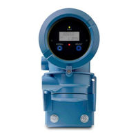
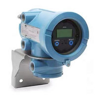
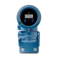
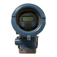
Emerson Micro Motion 1700 Transmitter Manuals
Manuals and User Guides for Emerson Micro Motion 1700 Transmitter. We have 9 Emerson Micro Motion 1700 Transmitter manuals available for free PDF download: Configuration And Use Manual, Installation Manual, Product Data Sheet
Emerson Micro Motion 1700 Configuration And Use Manual (328 pages)
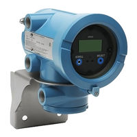
Transmitters with Analog Outputs
Brand: Emerson
|
Category: Transmitter
|
Size: 5 MB
Table of Contents
Advertisement
Emerson Micro Motion 1700 Configuration And Use Manual (282 pages)
Brand: Emerson
|
Category: Transmitter
|
Size: 8 MB
Table of Contents

Emerson Micro Motion 1700 Configuration And Use Manual (248 pages)
Transmitters with
Analog Outputs
Brand: Emerson
|
Category: Measuring Instruments
|
Size: 5 MB
Table of Contents
Advertisement
Emerson Micro Motion 1700 Configuration And Use Manual (218 pages)
Transmitters with Intrinsically Safe Outputs
Brand: Emerson
|
Category: Industrial Equipment
|
Size: 6 MB
Table of Contents

Emerson Micro Motion 1700 Installation Manual (122 pages)
Brand: Emerson
|
Category: Transmitter
|
Size: 12 MB
Table of Contents
Emerson Micro Motion 1700 Installation Manual (80 pages)
Emerson Satellite Radio User Manual
Brand: Emerson
|
Category: Transmitter
|
Size: 6 MB
Table of Contents
Emerson Micro Motion 1700 Installation Manual (92 pages)
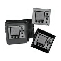
MVD Transmitters
Brand: Emerson
|
Category: Transmitter
|
Size: 16 MB
Table of Contents

Emerson Micro Motion 1700 Installation Manual (80 pages)
Brand: Emerson
|
Category: Transmitter
|
Size: 6 MB
Table of Contents
Emerson Micro Motion 1700 Product Data Sheet (28 pages)
Micro Motion 3000 Series Transmitters and Discrete Controllers
Brand: Emerson
|
Category: Transmitter
|
Size: 0 MB