Emerson Micro Motion 1700 Configuration And Use Manual
Transmitters with analog outputs
Hide thumbs
Also See for Micro Motion 1700:
- Configuration and use manual (248 pages) ,
- Installation manual (122 pages) ,
- Product data sheet (28 pages)

Related Manuals for Emerson Micro Motion 1700


Summary of Contents for Emerson Micro Motion 1700
-
Page 1: Analog Outputs
Configuration and Use Manual MMI-20019028, Rev AA March 2012 ® Micro Motion Model 1700 Transmitters with Analog Outputs Configuration and Use Manual... - Page 2 Safety messages are provided throughout this manual to protect personnel and equipment. Read each safety message carefully before proceeding to the next step. Micro Motion customer service Location Telephone number Email U.S.A. 800-522-MASS (800-522-6277) (toll free) flow.support@emerson.com Canada and Latin America +1 303-527-5200 (U.S.A.) Asia Japan 3 5769-6803 All other locations +65 6777-8211 (Singapore) Europe U.K.
-
Page 3: Table Of Contents
Contents Contents Part I Getting Started Chapter 1 Before you begin ......................3 About this manual .........................3 Transmitter model code ........................3 Communications tools and protocols ....................3 Additional documentation and resources ..................4 Chapter 2 Quick start ........................7 Power up the transmitter .......................7 Check flowmeter status .........................7 Make a startup connection to the transmitter ................9 Characterize the flowmeter (if required) ..................10... - Page 4 Contents Configure density measurement ....................45 4.5.1 Configure Density Measurement Unit ................46 4.5.2 Configure slug flow parameters ..................47 4.5.3 Configure Density Damping ..................48 4.5.4 Configure Density Cutoff ....................50 Configure temperature measurement ..................50 4.6.1 Configure Temperature Measurement Unit ..............51 4.6.2 Configure Temperature Damping .................51 Configure pressure compensation ....................52...
- Page 5 Contents 6.3.2 Configure Frequency Output Scaling Method ...............90 6.3.3 Configure Frequency Output Maximum Pulse Width ............92 6.3.4 Configure Frequency Output Fault Action and Frequency Output Fault Level ....93 Configure the discrete output .....................94 6.4.1 Configure Discrete Output Source ................95 6.4.2 Configure Discrete Output Polarity ................97 6.4.3 Configure Discrete Output Fault Action ................98...
- Page 6 Contents 9.3.1 Zero the flowmeter using the display ................147 9.3.2 Zero the flowmeter using ProLink II ................148 9.3.3 Zero the flowmeter using ProLink III ................149 9.3.4 Zero the flowmeter using the Field Communicator .............151 Validate the meter ........................152 9.4.1 Alternate method for calculating the meter factor for volume flow ......153 Perform a (standard) D1 and D2 density calibration ..............154 9.5.1 Perform a D1 and D2 density calibration using ProLink II ..........154...
- Page 7 Contents 10.29 Check the core processor LED ....................203 10.29.1 Core processor LED states ...................205 10.30 Perform a core processor resistance test ...................207 Appendices and reference Appendix A Using the transmitter display ..................211 Components of the transmitter interface ..................211 Use the optical switches ......................212 Access and use the display menu system ...................213 A.3.1 Enter a floating-point value using the display ..............214...
- Page 8 Contents ® Micro Motion Model 1700 Transmitters with Analog Outputs...
-
Page 9: Part I Getting Started
Getting Started Part I Getting Started Chapters covered in this part: • Before you begin • Quick start Configuration and Use Manual... - Page 10 Getting Started ® Micro Motion Model 1700 Transmitters with Analog Outputs...
-
Page 11: Before You Begin
Before you begin Before you begin Topics covered in this chapter: • About this manual • Transmitter model code • Communications tools and protocols • Additional documentation and resources About this manual This manual provides information to help you configure, commission, use, maintain, and troubleshoot the Micro Motion Model 1700 transmitter. -
Page 12: Additional Documentation And Resources
Appendix Micro Motion web site (www.micromo- tion.com You may be able to use other communications tools from Emerson Process Management, such as ™ AMS Suite: Intelligent Device Manager, or the Smart Wireless THUM Adapter. Use of AMS or the Smart Wireless THUM Adapter is not discussed in this manual. The AMS interface is similar to the ProLink II interface. - Page 13 Before you begin Table 1-2: Additional documentation and resources (continued) Topic Document Transmitter installation Micro Motion Model 1700 and Model 2700 Transmitters: Installation Manual Hazardous area installa- See the approval documentation shipped with the transmitter, or tion download the appropriate documentation from the Micro Motion web site at www.micromotion.com.
- Page 14 Before you begin ® Micro Motion Model 1700 Transmitters with Analog Outputs...
-
Page 15: Chapter 2 Quick Start
Quick start Quick start Topics covered in this chapter: • Power up the transmitter • Check flowmeter status • Make a startup connection to the transmitter • Characterize the flowmeter (if required) • Verify mass flow measurement • Verify the zero Power up the transmitter The transmitter must be powered up for all configuration and commissioning tasks, or for process measurement. - Page 16 Quick start Wait approximately 10 seconds for the power-up sequence to complete. Immediately after power-up, the transmitter runs through diagnostic routines and checks for error conditions. During the power-up sequence, Alarm A009 is active. This alarm should clear automatically when the power-up sequence is complete. Check the status LED on the transmitter.
-
Page 17: Make A Startup Connection To The Transmitter
Quick start Make a startup connection to the transmitter For all configuration tools except the display, you must have an active connection to the transmitter to configure the transmitter. Follow this procedure to make your first connection to the transmitter. Identify the connection type to use, and follow the instructions for that connection type in the appropriate appendix. -
Page 18: Characterize The Flowmeter (If Required)
Quick start Characterize the flowmeter (if required) Display Not available ProLink II • ProLink > Configuration > Device > Sensor Type • ProLink > Configuration > Flow • ProLink > Configuration > Density • ProLink > Configuration > T Series ProLink III Device Tools >... -
Page 19: Index
Quick start • Older curved-tube sensors (all sensors except T-Series): see Figure 2-1 • Newer curved-tube sensors (all sensors except T-Series): see Figure 2-2 • Older straight-tube sensors (T-Series): see Figure 2-3 • Newer straight-tube sensors (T-Series): see Figure 2-4 Figure 2-1: Tag on older curved-tube sensors (all sensors except T-Series) Figure 2-2:... - Page 20 Quick start Figure 2-3: Tag on older straight-tube sensor (T-Series) Figure 2-4: Tag on newer straight-tube sensor (T-Series) Density calibration parameters (D1, D2, K1, K2, FD, DT, TC) If your sensor tag does not show a D1 or D2 value: •...
-
Page 21: Verify Mass Flow Measurement
Quick start If your sensor tag does not show a DT or TC value, enter the last 3 digits of the density calibration factor. In the sample tag, this value is shown as 4.44 (see Figure 2-1). Flow calibration parameters (FCF, FT) Two separate values are used to describe flow calibration: a 6-character FCF value and a 4- character FT value. -
Page 22: Verify The Zero
Quick start • Review the troubleshooting suggestions for flow measurement issues. See Section 10.3. Verify the zero Verifying the zero helps you determine if the stored zero value is appropriate to your installation, or if a field zero can improve measurement accuracy. The zero verification procedure analyzes the Live Zero value under conditions of zero flow, and compares it to the Zero Stability range for the sensor. -
Page 23: Verify The Zero Using Prolink Iii
Quick start If the zero verification procedure fails: a. Confirm that the sensor is completely blocked in, that flow has stopped, and that the sensor is completely full of process fluid. b. Verify that the process fluid is not flashing or condensing, and that it does not contain particles that can settle out. -
Page 24: Terminology Used With Zero Verification And Zero Calibration
Quick start If the zero verification procedure fails: a. Confirm that the sensor is completely blocked in, that flow has stopped, and that the sensor is completely full of process fluid. b. Verify that the process fluid is not flashing or condensing, and that it does not contain particles that can settle out. -
Page 25: Part Ii Configuration And Commissioning
Configuration and commissioning Part II Configuration and commissioning Chapters covered in this part: • Introduction to configuration and commissioning • Configure process measurement • Configure device options and preferences • Integrate the meter with the control system Completing the configuration •... - Page 26 Configuration and commissioning ® Micro Motion Model 1700 Transmitters with Analog Outputs...
-
Page 27: Introduction To Configuration And Commissioning
Introduction to configuration and commissioning Introduction to configuration and commissioning Topics covered in this chapter: • Configuration flowchart • Default values and ranges • Enable access to the off-line menu of the display • Disable write-protection on the transmitter configuration •... - Page 28 Introduction to configuration and commissioning Figure 3-1: Configuration flowchart Configure device options and Test and move to production Configure process measurement preferences Configure mass flow Test or tune transmitter Configure display measurement using sensor simulation parameters Configure volume flow meaurement Configure fault handling Back up transmitter parameters...
-
Page 29: Default Values And Ranges
Introduction to configuration and commissioning Default values and ranges Section E.1 to view the default values and ranges for the most commonly used parameters. Enable access to the off-line menu of the display Display OFF-LINE MAINT > OFF-LINE CONFG > DISPLAY ProLink II ProLink >... -
Page 30: Restore The Factory Configuration
Introduction to configuration and commissioning Write-protecting the transmitter prevents accidental changes to configuration. It does not prevent normal operational use. You can always disable write-protection, perform any required configuration changes, then re-enable write-protection. Restore the factory configuration Display Not available ProLink II ProLink >... -
Page 31: Configure Process Measurement
Configure process measurement Configure process measurement Topics covered in this chapter: • Configure mass flow measurement • Configure volume flow measurement for liquid applications • Configure gas standard volume (GSV) flow measurement • Configure Flow Direction • Configure density measurement •... - Page 32 Configure process measurement If the measurement unit you want to use is not available, you can define a special measurement unit. Options for Mass Flow Measurement Unit The transmitter provides a standard set of measurement units for Mass Flow Measurement Unit, plus one user-defined special measurement unit.
- Page 33 Configure process measurement Define a special measurement unit for mass flow Display Not available ProLink II ProLink > Configuration > Special Units ProLink III Device Tools > Configuration > Process Measurement > Flow > Special Units Field Communicator Configure > Manual Setup > Measurements > Special Units > Mass Special Units Overview A special measurement unit is a user-defined unit of measure that allows you to report process data, totalizer data, and inventory data in a unit that is not available in the...
-
Page 34: Configure Flow Damping
Configure process measurement a. 1 lb/sec = 16 oz/sec b. Mass Flow Conversion Factor = 1/16 = 0.0625 Set Mass Flow Conversion Factor to 0.0625. Set Mass Flow Label to oz/sec. Set Mass Total Label to oz. 4.1.2 Configure Flow Damping Display Not available ProLink II... -
Page 35: Configure Mass Flow Cutoff
Configure process measurement • In general, lower damping values are preferable because there is less chance of data loss, and less lag time between the actual measurement and the reported value. • For gas applications, Micro Motion recommends setting Flow Damping to 2.56 or higher. The value you enter is automatically rounded down to the nearest valid value. - Page 36 Configure process measurement Procedure Set Mass Flow Cutoff to the value you want to use. The default value for Mass Flow Cutoff is 0.0 g/sec or a sensor-specific value set at the factory. The recommended setting is 0.05% of the sensor's rated maximum flow rate or a value below the highest expected flow rate.
-
Page 37: Configure Volume Flow Measurement For Liquid Applications
Configure process measurement The frequency output will report the actual flow rate, and the actual flow rate will be used in all internal processing. • If the mass flow rate drops below 10 g/sec, both outputs will report zero flow, and 0 will be used in all internal processing. -
Page 38: Configure Volume Flow Measurement Unit For Liquid Applications
Configure process measurement 4.2.2 Configure Volume Flow Measurement Unit for liquid applications Display OFF-LINE MAINT > OFF-LINE CONFG > UNITS > VOL ProLink II ProLink > Configuration > Flow > Vol Flow Unit ProLink III Device Tools > Configuration > Process Measurement > Flow Field Communicator Configure >... - Page 39 Configure process measurement Table 4-3: Options for Volume Flow Measurement Unit for liquid applications (continued) Label Unit description Display ProLink II ProLink III Field Communica- M3/MIN m3/min m3/min Cum/min Cubic meters per minute M3/H m3/hr m3/hr Cum/h Cubic meters per hour M3/D m3/day m3/day...
- Page 40 Configure process measurement Define a special measurement unit for volume flow Display Not available ProLink II ProLink > Configuration > Special Units ProLink III Device Tools > Configuration > Process Measurement > Flow > Special Units Field Communicator Configure > Manual Setup > Measurements > Special Units > Volume Special Units Overview A special measurement unit is a user-defined unit of measure that allows you to report process data, totalizer data, and inventory data in a unit that is not available in the...
-
Page 41: Configure Volume Flow Cutoff
Configure process measurement a. 1 gal/sec = 8 pints/sec b. Volume Flow Conversion Factor = 1/8 = 0.1250 Set Volume Flow Conversion Factor to 0.1250. Set Volume Flow Label to pints/sec. Set Volume Total Label to pints. 4.2.3 Configure Volume Flow Cutoff Display Not available ProLink II... -
Page 42: Configure Gas Standard Volume (Gsv) Flow Measurement
Configure process measurement Result: If the volume flow rate drops below 15 l/sec, volume flow will be reported as 0, and 0 will be used in all internal processing. Example: Cutoff interaction with AO Cutoff higher than Volume Flow Cutoff Configuration: •... -
Page 43: Configure Volume Flow Type For Gas Applications
Configure process measurement 4.3.1 Configure Volume Flow Type for gas applications Not available Display ProLink II ProLink > Configuration > Flow > Vol Flow Type ProLink III Device Tools > Configuration > Process Measurement > Flow Field Communicator Configure > Manual Setup > Measurements > GSV > Volume Flow Type > Standard Gas Volume Overview Volume Flow Type controls whether liquid or gas standard volume flow measurement is used. -
Page 44: Configure Gas Standard Volume Flow Measurement Unit
Configure process measurement 4.3.3 Configure Gas Standard Volume Flow Measurement Unit Display OFF-LINE MAINT > OFF-LINE CONFG > UNITS > GSV ProLink II ProLink > Configuration > Flow > Std Gas Vol Flow Unit ProLink III Device Tools > Configuration > Process Measurement > Flow Field Communicator Configure >... - Page 45 Configure process measurement Table 4-4: Options for Gas Standard Volume Measurement Unit (continued) Label Unit description Display ProLink II ProLink III Field Communica- NLPM NLPM NLPM NLPM Normal liter per minute NLPH NLPH NLPH NLPH Normal liter per hour NLPD NLPD NLPD NLPD...
- Page 46 Configure process measurement Note Although you cannot define a special measurement unit using the display, you can use the display to select an existing special measurement unit, and to view process data using the special measurement unit. Procedure Specify Base Gas Standard Volume Unit. Base Gas Standard Volume Unit is the existing gas standard volume unit that the special unit will be based on.
-
Page 47: Configure Gas Standard Volume Flow Cutoff
Configure process measurement 4.3.4 Configure Gas Standard Volume Flow Cutoff Not available Display ProLink II ProLink > Configuration > Flow > Std Gas Vol Flow Cutoff ProLink III Device Tools > Configuration > Process Measurement > Flow Field Communicator Configure > Manual Setup > Measurements > GSV > GSV Cutoff Overview Gas Standard Volume Flow Cutoff specifies the lowest gas standard volume flow rate that will reported as measured. -
Page 48: Configure Flow Direction
Configure process measurement Example: Cutoff interaction with AO Cutoff higher than Gas Standard Volume Flow Cutoff Configuration: • mA Output Process Variable for the primary mA output: Gas Standard Volume Flow Rate • Frequency Output Process Variable: Gas Standard Volume Flow Rate •... -
Page 49: Options For Flow Direction
Configure process measurement 4.4.1 Options for Flow Direction Table 4-5: Options for Flow Direction Flow Direction setting Relationship to Flow Direction ar- row on sensor ProLink II ProLink III Field Communicator Forward Forward Forward Appropriate when the Flow Direction arrow is in the same direction as the majority of flow. - Page 50 Configure process measurement Figure 4-1: Effect of Flow Direction on the mA output: Lower Range Value = 0 Flow Direction = Forward Flow Direction = Reverse, Negate Forward Flow Direction = Absolute Value, Bidirectional, Negate Bidirectional Reverse flow Forward flow Reverse flow Forward flow Reverse flow...
- Page 51 Configure process measurement • Under conditions of reverse flow or zero flow, the mA output is 4 mA. • Under conditions of forward flow, up to a flow rate of 100 g/sec, the mA output varies between 4 mA and 20 mA in proportion to the flow rate. •...
- Page 52 Configure process measurement Effect of Flow Direction on frequency outputs Flow Direction affects how the transmitter reports flow values via the frequency outputs. The frequency outputs are affected by Flow Direction only if Frequency Output Process Variable is set to a flow variable. Table 4-6: Effect of the Flow Direction parameter and actual flow direction on frequency outputs...
-
Page 53: Configure Density Measurement
Configure process measurement Table 4-8: Effect of the Flow Direction parameter and actual flow direction on flow values reported via digital communications Flow Direction setting Actual flow direction Forward Zero flow Reverse Forward Positive Negative Reverse Positive Negative Bidirectional Positive Negative Absolute Value Positive... -
Page 54: Configure Density Measurement Unit
Configure process measurement 4.5.1 Configure Density Measurement Unit Display OFF-LINE MAINT > OFF-LINE CONFG > UNITS > DENS ProLink II ProLink > Configuration > Density > Dens Unit ProLink III Device Tools > Configuration > Process Measurement > Density Field Communicator Configure > Manual Setup > Measurements > Density > Density Unit Overview Density Measurement Unit specifies the units of measure that will be displayed for density measurement. -
Page 55: Configure Slug Flow Parameters
Configure process measurement 4.5.2 Configure slug flow parameters Not available Display ProLink II • ProLink > Configuration > Density > Slug High Limit • ProLink > Configuration > Density > Slug Low Limit • ProLink > Configuration > Density > Slug Duration ProLink III Device Tools >... -
Page 56: Configure Density Damping
Configure process measurement The default value for Slug High Limit is 5.0 g/cm . The range is 0.0 to 10.0 g/cm Set Slug Duration to the number of seconds that the transmitter will wait for a slug flow condition to clear before performing the configured slug flow action. The default value for Slug Duration is 0.0 seconds. - Page 57 Configure process measurement Overview Damping is used to smooth out small, rapid fluctuations in process measurement. Damping Value specifies the time period (in seconds) over which the transmitter will spread changes in the reported process variable. At the end of the interval, the reported process variable will reflect 63% of the change in the actual measured value.
-
Page 58: Configure Density Cutoff
Configure process measurement Interaction between Density Damping and Added Damping In some circumstances, both Density Damping and Added Damping are applied to the reported density value. Density Damping controls the rate of change in the density process variable. Added Damping controls the rate of change reported via the mA output. -
Page 59: Configure Temperature Measurement Unit
Configure process measurement 4.6.1 Configure Temperature Measurement Unit Display OFF-LINE MAINT > OFF-LINE CONFG > UNITS > TEMP ProLink II ProLink > Configuration > Temperature > Temp Unit ProLink III Device Tools > Configuration > Process Measurement > Temperature Field Communicator Configure > Manual Setup > Measurements > Temperature > Temperature Unit Overview Temperature Measurement Unit specifies the unit that will be used for temperature measurement. -
Page 60: Configure Pressure Compensation
Configure process measurement Overview Damping is used to smooth out small, rapid fluctuations in process measurement. Damping Value specifies the time period (in seconds) over which the transmitter will spread changes in the reported process variable. At the end of the interval, the reported process variable will reflect 63% of the change in the actual measured value. - Page 61 Configure process measurement Prerequisites You will need the flow factor, density factor, and calibration pressure values for your sensor. • For the flow factor and density factor, see the product data sheet for your sensor. • For the calibration pressure, see the calibration sheet for your sensor. If the data is unavailable, use 20 PSI.
-
Page 62: Configure Pressure Compensation Using Prolink Iii
Configure process measurement Option Setup Polling for pressure a. Ensure that the primary mA output has been wired to support HART polling. b. Choose ProLink > Configuration > Polled Variables. c. Choose an unused polling slot. d. Set Polling Control to Poll As Primary or Poll as Secondary, and click Apply. - Page 63 Configure process measurement The flow factor is the percent change in the flow rate per PSI. When entering the value, reverse the sign. Example: If the flow factor is 0.000004 % per PSI, enter −0.000004 % per PSI. Enter Density Factor for your sensor. The density factor is the change in fluid density, in g/cm /PSI.
-
Page 64: Configure Pressure Compensation Using The Field Communicator
Configure process measurement If you want to use digital communications, click Apply, then perform the necessary host programming and communications setup to write temperature data to the transmitter at appropriate intervals. Postrequisites If you are using an external pressure value, verify the setup by checking the External Pressure value displayed in the Inputs area of the main window. -
Page 65: Options For Pressure Measurement Unit
Configure process measurement Option Setup A user-configured a. Set Pressure Unit to the desired unit. static pressure val- b. Set Compensation Pressure to the desired value. Polling for pressure a. Ensure that the primary mA output has been wired to support HART polling. - Page 66 Configure process measurement Table 4-13: Options for Pressure Measurement Unit (continued) Label Unit description Display ProLink II ProLink III Field Communica- mmH2O mm Water @ 68°F mmH2O Millimeters water @ 68 °F mm Water @ 68°F mmHG mm Mercury @ 0°C mmHg Millimeters mercury @ 0 °C mm Mercury @ 0°C...
-
Page 67: Configure Device Options And Preferences
Configure device options and preferences Configure device options and preferences Topics covered in this chapter: • Configure the transmitter display • Enable or disable operator actions from the display • Configure security for the display menus • Configure response time parameters •... -
Page 68: Configure The Process Variables Shown On The Display
Configure device options and preferences The languages available depend on your transmitter model and version. 5.1.2 Configure the process variables shown on the display Display Not available ProLink II ProLink > Configuration > Display ProLink III Device Tools > Configuration > Transmitter Display > Display Variables Field Communicator Configure >... -
Page 69: Configure The Precision Of Variables Shown On The Display
Configure device options and preferences Display variable Process variable assignment Display Variable 10 None Display Variable 11 None Display Variable 12 None Display Variable 13 None Display Variable 14 None Display Variable 15 None Configure Display Variable 1 to track the primary mA output Display OFF-LINE MAINT >... -
Page 70: Configure The Refresh Rate Of Data Shown On The Display
Configure device options and preferences Overview Setting Display Precision determines the precision (number of decimal places) shown on the display. You can set Display Precision independently for each variable. Setting Display Precision does not affect the actual value of the process variable. Procedure Select a process variable. -
Page 71: Enable Or Disable Automatic Scrolling Through The Display Variables
Configure device options and preferences 5.1.5 Enable or disable automatic scrolling through the display variables Display OFF-LINE MAINT > OFF-LINE CONFG > DISPLAY > AUTO SCRLL ProLink II ProLink > Configuration > Display > Display Options > Display Auto Scroll ProLink III Device Tools >... -
Page 72: Enable Or Disable Status Led Blinking
Configure device options and preferences Procedure Enable or disable Backlight. The default setting is Enabled. 5.1.7 Enable or disable Status LED Blinking Not available Display ProLink II ProLink > Configuration > Display > Display Options > Display Status LED Blinking ProLink III Device Tools >... -
Page 73: Enable Or Disable Totalizer Start/Stop From The Display
Configure device options and preferences 5.2.1 Enable or disable Totalizer Start/Stop from the display Display OFF-LINE MAINT > OFF-LINE CONFG > DISPLAY > TOTALS STOP ProLink II ProLink > Configuration > Display > Display Options > Display Start/Stop Totalizers ProLink III Device Tools >... -
Page 74: Enable Or Disable The Acknowledge All Alarms Display Command
Configure device options and preferences Restrictions • This parameter does not apply to inventories. You cannot reset inventories from the display. • You cannot use the display to reset all totalizers as a group. You must reset totalizers individually. • If the petroleum measurement application is installed on your computer, the operator must enter the off-line password to perform this function, even if the off-line password is not enabled. -
Page 75: Configure Security For The Display Menus
Configure device options and preferences Option Description Enabled (default) Operators can use a single display command to acknowledge all alarms at once. Disabled Operators cannot acknowledge all alarms at once, they must be ac- knowledged individually. Configure security for the display menus Display OFF-LINE MAINT >... -
Page 76: Configure Response Time Parameters
Configure device options and preferences To require a password for access to the maintenance section of the off-line menu and the Smart Meter Verification menu, enable or disable Off-Line Password. Option Description Enabled Operator is prompted for the off-line password at entry to the Smart Meter Verification menu (if applicable) or entry to the maintenance section of the off-line menu. -
Page 77: Configure Update Rate
Configure device options and preferences 5.4.1 Configure Update Rate Not available Display ProLink II ProLink > Configuration > Device > Update Rate ProLink III Device Tools > Configuration > Process Measurement > Response > Update Rate Field Communicator Configure > Manual Setup > Measurements > Update Rate Overview Update Rate controls the rate at which process data is polled and process variables are calculated. -
Page 78: Configure Calculation Speed (Response Time)
Configure device options and preferences Effects of Update Rate = Special Incompatible features and functions Special mode is not compatible with the following features and functions: • Enhanced events. Use basic events instead. • All calibration procedures. • Zero verification. •... -
Page 79: Configure Alarm Handling
Configure device options and preferences Overview Calculation Speed is used to apply a different algorithm to the calculation of process variables from the raw process data. Calculation Speed = Special produces faster and “noisier” response to changes in the process. In ProLink II, Calculation Speed is called Response Time. -
Page 80: Configure Status Alarm Severity
Configure device options and preferences Overview Fault Timeout controls the delay before fault actions are performed. Restriction Fault Timeout is applied only to the following alarms (listed by Status Alarm Code): A003, A004, A005, A008, A016, A017, A033. For all other alarms, fault actions are performed as soon as the alarm is detected. - Page 81 Configure device options and preferences Micro Motion recommends using the default settings for Status Alarm Severity unless you have a specific requirement to change them. Procedure Select a status alarm. For the selected status alarm, set Status Alarm Severity as desired. Option Description Fault...
- Page 82 Configure device options and preferences Table 5-2: Status alarms and Status Alarm Severity (continued) Alarm code Status message Default severity Notes Configurable? Fault A009 Transmitter Initializing/ Warming Up A010 Calibration Failure Fault A011 Zero Calibration Failed: Fault A012 Zero Calibration Failed: Fault High Fault...
- Page 83 Configure device options and preferences Table 5-2: Status alarms and Status Alarm Severity (continued) Alarm code Status message Default severity Notes Configurable? Meter Verification Aborted Informational A035 Applies only to transmitters with Smart Meter Verification. A100 mA Output 1 Saturated Informational Can be set to either Informational or Ignore, but cannot be set to Fault.
-
Page 84: Configure Informational Parameters
Configure device options and preferences Table 5-2: Status alarms and Status Alarm Severity (continued) Alarm code Status message Default severity Notes Configurable? Informational A132 Sensor Simulation Active Applies only to flowmeters with the enhanced core processor. Can be set to either Informational or Ignore, but cannot be set to Fault. -
Page 85: Configure Message
Configure device options and preferences Procedure Enter a description for the transmitter. You can use up to 16 characters for the description. 5.6.2 Configure Message Not available Display ProLink II ProLink > Configuration > Device > Message ProLink III Device Tools > Configuration > Informational Parameters > Transmitter Field Communicator Configure >... -
Page 86: Configure Sensor Serial Number
Configure device options and preferences 5.6.4 Configure Sensor Serial Number Not available Display ProLink II ProLink > Configuration > Sensor > Sensor S/N ProLink III Device Tools > Configuration > Informational Parameters > Sensor Field Communicator Configure > Manual Setup > Info Parameters > Sensor Information > Sensor Serial Number Overview Sensor Serial Number lets you store the serial number of the sensor component of your flowmeter in transmitter memory. -
Page 87: Configure Sensor Liner Material
Configure device options and preferences 5.6.6 Configure Sensor Liner Material Not available Display ProLink II ProLink > Configuration > Sensor > Liner Matl ProLink III Device Tools > Configuration > Informational Parameters > Sensor Field Communicator Configure > Manual Setup > Info Parameters > Sensor Information > Tube Lining Overview Sensor Liner Material lets you store the type of material used for your sensor liner in transmitter memory. - Page 88 Configure device options and preferences ® Micro Motion Model 1700 Transmitters with Analog Outputs...
-
Page 89: Integrate The Meter With The Control System
Integrate the meter with the control system Integrate the meter with the control system Topics covered in this chapter: • Configure the transmitter channels • Configure the mA output • Configure the frequency output • Configure the discrete output • Configure events •... -
Page 90: Configure The Ma Output
Integrate the meter with the control system Postrequisites For each channel that you configured, perform or verify the corresponding input or output configuration. When the configuration of a channel is changed, the channel’s behavior will be controlled by the configuration that is stored for the selected input or output type, and the stored configuration may not be appropriate for your process. -
Page 91: Configure Lower Range Value (Lrv) And Upper Range Value (Urv)
Integrate the meter with the control system • If you are using the HART variables, be aware that changing the configuration of mA Output Process Variable will change the configuration of the HART Primary Variable (PV) and the HART Tertiary Variable (TV). •... - Page 92 Integrate the meter with the control system Overview The Lower Range Value (LRV) and Upper Range Value (URV) are used to scale the mA output, that is, to define the relationship between mA Output Process Variable and the mA output level.
-
Page 93: Configure Ao Cutoff
Integrate the meter with the control system Table 6-2: Default values for Lower Range Value (LRV) and Upper Range Value (URV) Process variable All mass flow variables –200.000 g/sec 200.000 g/sec All liquid volume flow variables –0.200 l/sec 0.200 l/sec Gas standard volume flow –423.78 SCFM 423.78 SCFM... -
Page 94: Configure Added Damping
Integrate the meter with the control system Example: Cutoff interaction Configuration: • mA Output Process Variable = Mass Flow Rate • Frequency Output Process Variable = Mass Flow Rate • AO Cutoff = 10 g/sec • Mass Flow Cutoff = 15 g/sec Result: If the mass flow rate drops below 15 g/sec, all outputs representing mass flow will report zero flow. - Page 95 Integrate the meter with the control system Note Added Damping is not applied if the mA output is fixed (for example, during loop testing) or if the mA output is reporting a fault. Added Damping is applied while sensor simulation is active. Procedure Set Added Damping to the desired value.
-
Page 96: Configure Ma Output Fault Action And Ma Output Fault Level
Integrate the meter with the control system Result: A change in the mass flow rate will be reflected in the mA output over a time period that is greater than 3 seconds. The exact time period is calculated by the transmitter according to internal algorithms which are not configurable. -
Page 97: Configure The Frequency Output
Integrate the meter with the control system Table 6-4: Options for mA Output Fault Action and mA Output Fault Level (continued) mA Output Fault Level Option mA output behavior None Tracks data for the assigned process vari- Not applicable able; no fault action CAUTION! If you set mA Output Fault Action or Frequency Output Fault Action to None, be sure to set Digital Communications Fault Action to None. -
Page 98: Configure Frequency Output Polarity
Integrate the meter with the control system 6.3.1 Configure Frequency Output Polarity Display OFF-LINE MAINT > OFF-LINE CONFG > IO > CH B > SET FO > FO POLAR ProLink II ProLink > Configuration > Frequency/Discrete Output > Frequency > Freq Output Polarity ProLink III Device Tools >... - Page 99 Integrate the meter with the control system Overview Frequency Output Scaling Method defines the relationship between output pulse and flow units. Set Frequency Output Scaling Method as required by your frequency receiving device. Procedure Set Frequency Output Scaling Method. Option Description Frequency=Flow (default) Frequency calculated from flow rate...
-
Page 100: Configure Frequency Output Maximum Pulse Width
Integrate the meter with the control system If Frequency Output Scale Method is set to Frequency=Flow, and Frequency Output Maximum Pulse Width is set to a non-zero value, Micro Motion recommends setting Frequency Factor to a value below 200 Hz. Example: Configure Frequency=Flow You want the frequency output to report all flow rates up to 2000 kg/min. -
Page 101: Configure Frequency Output Fault Action And Frequency Output Fault Level
Integrate the meter with the control system Table 6-6: Interaction of Frequency Output Maximum Pulse Width and Frequency Output Polarity (continued) Polarity Pulse width Active Low Procedure Set Frequency Output Maximum Pulse Width as desired. The default value is 277 milliseconds. You can set Frequency Output Maximum Pulse Width to 0 milliseconds or to a value between 0.5 milliseconds and 277.5 milliseconds. -
Page 102: Configure The Discrete Output
Integrate the meter with the control system The default value is Downscale (0 Hz). If you set Frequency Output Fault Action to Upscale, set Frequency Fault Level to the desired value. The default value is 15000 Hz. The range is 10 to 15000 Hz. Options for Frequency Output Fault Action Table 6-7: Options for Frequency Output Fault Action... -
Page 103: Configure Discrete Output Source
Integrate the meter with the control system Important Whenever you change a discrete output parameter, verify all other discrete output parameters before returning the flowmeter to service. In some situations, the transmitter automatically loads a set of stored values, and these values may not be appropriate for your application. 6.4.1 Configure Discrete Output Source Display... - Page 104 Integrate the meter with the control system Table 6-8: Options for Discrete Output Source (continued) Label Discrete out- Option Condition put voltage Field Commu- Display ProLink II ProLink III nicator Event 1 or Event E1OR2 Event 1 or Event 1 or 2 Status Event 2 Event 2...
-
Page 105: Configure Discrete Output Polarity
Integrate the meter with the control system Procedure Set Discrete Output Source to Flow Switch, if you have not already done so. Set Flow Switch Variable to the flow variable that you want to use to control the flow switch. Set Flow Switch Setpoint to the value at which the flow switch will be triggered (after Hysteresis is applied). -
Page 106: Configure Discrete Output Fault Action
Integrate the meter with the control system Options for Discrete Output Polarity Table 6-9: Options for Discrete Output Polarity Polarity Description Active High • When asserted (condition tied to DO is true), the circuit provides a pull-up to 24 V. •... - Page 107 Integrate the meter with the control system Overview Discrete Output Fault Action controls the behavior of the discrete output if the transmitter encounters an internal fault condition. Note For some faults only: If Last Measured Value Timeout is set to a non-zero value, the transmitter will not implement the fault action until the timeout has elapsed.
-
Page 108: Configure Events
Integrate the meter with the control system Note If Discrete Output Source is set to Fault and a fault occurs, the discrete output is always ON. The setting of Discrete Output Fault Action is ignored. Configure events An event occurs when the real-time value of a user-specified process variable moves past a user-defined setpoint. -
Page 109: Configure An Enhanced Event
Integrate the meter with the control system Set a value for Setpoint A. (Optional) Configure a discrete output to switch states in response to the event status. 6.5.2 Configure an enhanced event Not available Display ProLink II ProLink > Configuration > Discrete Events ProLink III Device Tools >... - Page 110 Integrate the meter with the control system • For IN and OUT events, set Setpoint A and Setpoint B. (Optional) Configure a discrete output to switch states in response to the event status. (Optional) Specify the action or actions that the transmitter will perform when the event occurs.
-
Page 111: Configure Digital Communications
Integrate the meter with the control system Configure digital communications The digital communications parameters control how the transmitter will communicate using digital communications. Your transmitter supports the following types of digital communications: • HART/Bell 202 over the primary mA terminals •... - Page 112 Integrate the meter with the control system Ensure Loop Current Mode (mA Output Action) is configured appropriately. Options Description Enabled The primary mA output reports process data as configured. Disabled The primary mA output is fixed at 4 mA and does not report process data.
- Page 113 Integrate the meter with the control system Label Field Communi- ProLink II ProLink III cator Description Primary Variable Source (Primary The transmitter sends the primary Variable) variable (PV) in the configured measurement units in each burst (e.g., 14.0 g/sec, 13.5 g/sec, 12.0 g/sec).
- Page 114 Integrate the meter with the control system Restriction The TV is automatically set to match the PV and cannot be configured independently. Options for HART variables Table 6-12: Options for HART variables Process variable Primary Varia- Secondary Third Variable Fourth Varia- ble (PV) Variable (SV) (TV)
-
Page 115: Configure Hart/Rs-485 Communications
Integrate the meter with the control system 6.6.2 Configure HART/RS-485 communications Display OFF-LINE MAINT > OFF-LINE CONFG > COMM ProLink II ProLink > Configuration > Device > Digital Comm Settings > HART Address ProLink > Configuration > RS-485 ProLink III Device Tools >... -
Page 116: Configure Modbus/Rs-485 Communications
Integrate the meter with the control system 6.6.3 Configure Modbus/RS-485 communications Display OFF-LINE MAINT > OFF-LINE CONFG > COMM ProLink II ProLink > Configuration > Device > Digital Comm Settings ProLink III Device Tools > Configuration > Communications > RS-485 Terminals Field Communicator Configure >... -
Page 117: Configure Digital Communications Fault Action
Integrate the meter with the control system Set Parity, Stop Bits, and Baud Rate as appropriate for your network. Set Floating-Point Byte Order to match the byte order used by your Modbus host. Code Byte order 1–2 3–4 3–4 1–2 2–1 4–3 4–3 2–1 Table 6-14... - Page 118 Integrate the meter with the control system Overview Digital Communications Fault Action specifies the values that will be reported via digital communications if the transmitter encounters an internal fault condition. Procedure Set Digital Communications Fault Action as desired. The default setting is None. Options for Digital Communications Fault Action Table 6-15: Options for Digital Communications Fault Action...
- Page 119 Integrate the meter with the control system CAUTION! If you set mA Output Fault Action or Frequency Output Fault Action to None, be sure to set Digital Communications Fault Action to None. If you do not, the output will not report actual process data, and this may result in measurement errors or unintended consequences for your process.
- Page 120 Integrate the meter with the control system ® Micro Motion Model 1700 Transmitters with Analog Outputs...
-
Page 121: Completing The Configuration
Completing the configuration Completing the configuration Topics covered in this chapter: • Test or tune the system using sensor simulation • Back up transmitter configuration • Enable write-protection on the transmitter configuration Test or tune the system using sensor simulation Use sensor simulation to test the system's response to a variety of process conditions, including boundary conditions, problem conditions, or alarm conditions, or to tune the loop. -
Page 122: Sensor Simulation
Completing the configuration Option Required values Sine Period Minimum Maximum For density, set Wave Form as desired and enter the required values. Option Required values Fixed Fixed Value Sawtooth Period Minimum Maximum Sine Period Minimum Maximum For temperature, set Wave Form as desired and enter the required values. Option Required values Fixed... -
Page 123: Back Up Transmitter Configuration
Completing the configuration • All mass flow rate, temperature, and density values shown on the display or reported via outputs or digital communications • The mass total and mass inventory values • All volume calculations and data, including reported values, volume totals, and volume inventories •... -
Page 124: Enable Write-Protection On The Transmitter Configuration
Completing the configuration Enable write-protection on the transmitter configuration Display OFF-LINE MAINT > CONFIG > LOCK ProLink II ProLink > Configuration > Device > Enable Write Protection ProLink III Device Tools > Configuration > Write-Protection Field Communicator Configure > Manual Setup > Info Parameters > Transmitter Info > Write Protect Overview If the transmitter is write-protected, the configuration is locked and nobody can change it until it is unlocked. -
Page 125: Part Iii Operations, Maintenance, And Troubleshooting
Operations, maintenance, and troubleshooting Part III Operations, maintenance, and troubleshooting Chapters covered in this part: • Transmitter operation • Measurement support • Troubleshooting Configuration and Use Manual... - Page 126 Operations, maintenance, and troubleshooting ® Micro Motion Model 1700 Transmitters with Analog Outputs...
-
Page 127: Chapter 8 Transmitter Operation
Transmitter operation Transmitter operation Topics covered in this chapter: • Record the process variables • View process variables • View transmitter status using the status LED • View and acknowledge status alarms • Read totalizer and inventory values • Start and stop totalizers and inventories •... -
Page 128: View Process Variables
Transmitter operation View process variables Display Scroll to the desired process variable. If AutoScroll is enabled, you can wait until the proc- ess variable is displayed. See Section 8.2.1 for more information. ProLink II ProLink > Process Variables ProLink III View the desired variable on the main screen under Process Variables. -
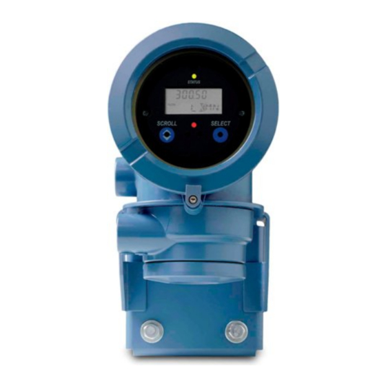
Page 129: View Process Variables Using Prolink Iii
Transmitter operation Figure 8-1: Transmitter display features A. Status LED B. Display (LCD panel) C. Process variable D. Scroll optical switch E. Optical switch indicator: turns red when either Scroll or Select is activated F. Select optical switch G. Unit of measure for process variable H. -
Page 130: View Transmitter Status Using The Status Led
Transmitter operation View transmitter status using the status LED The status LED shows the current alarm condition of the transmitter. The status LED is located on the face of the transmitter. Observe the status LED. • If your transmitter has a display, you can view the status LED with the transmitter housing cover in place. - Page 131 Transmitter operation Prerequisites Operator access to the alarm menu must be enabled (default setting). If operator access to the alarm menu is disabled, you must use another method to view or acknowledge status alarms. Procedure Figure 8-2. Configuration and Use Manual...
- Page 132 Transmitter operation Figure 8-2: Using the display to view and acknowledge the status alarms Scroll and Select simultaneously for 4 seconds SEE ALARM Select Is ACK ALL enabled? ACK ALL Select Scroll EXIT Select Scroll Active/ unacknowledged alarms? Alarm code NO ALARM Scroll Select...
-
Page 133: View And Acknowledge Alarms Using Prolink Ii
Transmitter operation Postrequisites • To clear the following alarms, you must correct the problem, acknowledge the alarm, then power-cycle the transmitter: A001, A002, A010, A011, A012, A013, A018, A019, A022, A023, A024, A025, A028, A029, A031. • For all other alarms: If the alarm is inactive when it is acknowledged, it will be removed from the list. -
Page 134: View And Acknowledge Alerts Using Prolink Iii
Transmitter operation 8.4.3 View and acknowledge alerts using ProLink III You can view a list containing all alerts that are active, or inactive and have been unacknowleged. From this list, you can acknowlege individual alerts or choose to acknowledge all alerts at once. View alerts on the ProLink III main screen under Alerts. -
Page 135: Alarm Data In Transmitter Memory
Transmitter operation • To refresh the list of active or unacknowledged alarms, press Service Tools > Alerts > Refresh Alerts. 8.4.5 Alarm data in transmitter memory The transmitter maintains three sets of data for every alarm that is posted. For each alarm occurrence, the following three sets of data are maintained in transmitter memory: •... -
Page 136: Start And Stop Totalizers And Inventories
Transmitter operation Overview Totalizers keep track of the total amount of mass or volume measured by the transmitter since the last totalizer reset. Inventories keep track of the total amount of mass or volume measured by the transmitter since the last inventory reset. You can use the inventories to keep a running total of mass or volume across multiple totalizer resets. - Page 137 Transmitter operation 1. Scroll until the word TOTAL appears in the lower left corner of the display. Important Because all totalizers are started or stopped together, it does not matter which total you use. 2. Select. 3. Scroll until START appears beneath the current totalizer value. 4.
-
Page 138: Reset Totalizers
Transmitter operation Reset totalizers Display Section 8.7.1. ProLink II ProLink > Totalizer Control > Reset Mass Total ProLink > Totalizer Control > Reset Volume Total ProLink > Totalizer Control > Reset Gas Volume Total ProLink > Totalizer Control > Reset ProLink III Device Tools >... -
Page 139: Reset Inventories
Transmitter operation 3. Scroll until RESET appears beneath the current totalizer value. 4. Select. 5. Select again to confirm. 6. Scroll to EXIT. 7. Select. • To reset the volume totalizer: 1. Scroll until the volume totalizer value appears. 2. Select. 3. - Page 140 Transmitter operation Overview When you reset an inventory, the transmitter sets its value to 0. It does not matter whether the inventory is started or stopped. If the inventory is started, it continues to track process measurement. When you reset a single inventory, the values of other inventories are not reset. Totalizer values are not reset.
-
Page 141: Chapter 9 Measurement Support
Measurement support Measurement support Topics covered in this chapter: • Options for measurement support • Use Smart Meter Verification • Zero the flowmeter • Validate the meter • Perform a (standard) D1 and D2 density calibration • Perform a D3 and D4 density calibration (T-Series sensors only) •... -
Page 142: Smart Meter Verification Requirements
Measurement support 9.2.1 Smart Meter Verification requirements To use Smart Meter Verification, the transmitter must be paired with an enhanced core processor, and the Smart Meter Verification option must be ordered for the transmitter. Table 9-1 for the minimum version of the transmitter, enhanced core processor, and communication tool needed to support Smart Meter Verification. -
Page 143: Run Smart Meter Verification
Measurement support Smart Meter Verification has an output mode called Continuous Measurement that allows the transmitter to keep measuring while the test is in progress. If you choose to run the test in Last Measured Value or Fault modes instead, the transmitter outputs will be held constant for the two minute duration of the test. - Page 144 Measurement support Option Description Last Value During the test, all outputs will go to their configured fault action. The test will run for approximately 140 seconds. While the test is in progress, dots traverse the display and test progress is shown. Postrequisites View the test results and take any appropriate actions.
- Page 145 Measurement support Smart Meter Verification flowchart: Running a test using the display Figure 9-2: Running a Smart Meter Verification test using the display RUN VERFY Select OUTPUTS EXIT Scroll Select CONTINUE MEASR FAULT LAST VALUE EXIT Scroll Scroll Scroll Select Select Select ARE YOU SURE/YES?
- Page 146 Measurement support You may need to wait a few seconds while ProLink II synchronizes its database with the transmitter data. Review the information presented on the screen, and click Next. Enter any desired information on the Test Definition screen, and click Next. All information on this screen is optional.
-
Page 147: View Test Data
Measurement support Postrequisites View the test results and take any appropriate actions. Run a Smart Meter Verification test using the Field Communicator Navigate to the Smart Meter Verification menu: • Overview > Shortcuts > Meter Verification • Service Tools > Maintenance > Routine Maintenance > Meter Verification Choose Manual Verification. - Page 148 Measurement support • Current flowmeter identification data • Current flow and density configuration parameters • Current zero values • Current process values for mass flow rate, volume flow rate, density, temperature, and external pressure • Customer and test descriptions (if entered by the user) If you use ProLink II or ProLink III to run a test, a test result chart and a test report are displayed at the completion of the test.
- Page 149 Measurement support Smart Meter Verification flowchart: Viewing test results using the display Figure 9-4: Viewing Smart Meter Verification test results using the display RESULTS READ Select RUNCOUNT x Select Scroll Pass Result type Abort Fail xx HOURS xx HOURS xx HOURS Select Select Select...
- Page 150 Measurement support View test result data using ProLink II Choose Tools > Meter Verification > Run Meter Verification and click View Previous Test Results and Print Report. The chart shows test results for all tests stored in the ProLink II database. (Optional) Click Next to view and print a test report.
-
Page 151: Schedule Automatic Execution Of The Smart Meter Verification Test
Measurement support Fail The test result is not within the specification uncertainty limit. Micro Motion recommends that you immediately repeat the meter verification test. If during the failed test you had set outputs to Continue Measurement, set outputs to Fault or Last Measured Value instead. - Page 152 Measurement support Manage scheduled test execution using the display Navigate to the Smart Meter Verification menu. Figure 9-5: Smart Meter Verification – Top-level menu Scroll and Select simultaneously for 4 seconds Scroll ENTER METER VERFY Select RUN VERFY RESULTS READ SCHEDULE VERFY EXIT Scroll...
- Page 153 Measurement support Smart Meter Verification flowchart: Scheduling test execution using the display Figure 9-6: Scheduling Smart Meter Verification test execution using the display SCHEDULE VERFY Select Schedule set? SCHED IS OFF TURN OFF SCHED/YES? Scroll Scroll Select Schedule deleted HOURS LEFT Scroll Select xx HOURS...
-
Page 154: Zero The Flowmeter
Measurement support To disable scheduled execution: • To disable execution of a single scheduled test, set Hours Until Next Run to 0. • To disable recurring execution, set Hours Between Recurring Runs to 0. • To disable all scheduled execution, click Turn Off Schedule. Manage scheduled test execution using ProLink III Choose Device Tools >... -
Page 155: Zero The Flowmeter Using The Display
Measurement support • The zero is required by site procedures. • The stored zero value fails the Zero Verification procedure. Prerequisites Before performing a field zero, execute the Zero Verification procedure to see whether or not a field zero can improve measurement accuracy. See Section 2.6. -
Page 156: Zero The Flowmeter Using Prolink Ii
Measurement support Navigate to OFFLINE MAINT > ZERO > CAL ZERO and select CAL/YES?. Dots traverse the display while flowmeter zero is in progress. Read the zero result on the display. The display reports CAL PASS if the zero was successful, or CAL FAIL if it was not. Postrequisites Restore normal flow through the sensor by opening the valves. -
Page 157: Zero The Flowmeter Using Prolink Iii
Measurement support Click Calibrate Zero. Modify Zero Time, if desired. Zero Time controls the amount of time the transmitter takes to determine its zero- flow reference point. The default Zero Time is 20 seconds. For most applications, the default Zero Time is appropriate. Click Perform Auto Zero. - Page 158 Measurement support a. Allow the flowmeter to warm up for at least 20 minutes after applying power. b. Run the process fluid through the sensor until the sensor temperature reaches the normal process operating temperature. c. Stop flow through the sensor by shutting the downstream valve, and then the upstream valve if available.
-
Page 159: Zero The Flowmeter Using The Field Communicator
Measurement support 9.3.4 Zero the flowmeter using the Field Communicator Zeroing the flowmeter establishes a baseline for process measurement by analyzing the sensor's output when there is no flow through the sensor tubes. Prepare the flowmeter: a. Allow the flowmeter to warm up for at least 20 minutes after applying power. b. -
Page 160: Validate The Meter
Measurement support Validate the meter Display OFF-LINE MAINT > CONFG > UNITS > MTR F ProLink II ProLink > Configuration > Flow ProLink III Device Tools > Configuration > Process Measurement > Flow Device Tools > Configuration > Process Measurement > Density Field Communicator Configure >... -
Page 161: Alternate Method For Calculating The Meter Factor For Volume Flow
Measurement support Procedure Determine the meter factor as follows: a. Use the flowmeter to take a sample measurement. b. Measure the same sample using the reference device. c. Calculate the meter factor using the following formula: ReferenceMeasurement NewMeterFactor ConfiguredMeterFactor FlowmeterMeasurement Ensure that the calculated meter factor is between 0.8 and 1.2, inclusive. -
Page 162: Perform A (Standard) D1 And D2 Density Calibration
Measurement support MeterFactor Volume MeterFactor Density Note The following equation is mathematically equivalent to the first equation. You may use whichever version you prefer. Density Flowmeter MeterFactor ConfiguredMeterFactor Volume Density Density ReferenceDevice Ensure that the calculated meter factor is between 0.8 and 1.2, inclusive. If the meter factor is outside these limits, contact Micro Motion customer service. - Page 163 Measurement support • If LD Optimization is enabled on your meter, disable it. To do this, choose ProLink > Configuration > Sensor and ensure that the checkbox is not checked. LD Optimization is used only with large sensors in hydrocarbon applications. In some installations, only Micro Motion customer service has access to this parameter.
-
Page 164: Perform A D1 And D2 Density Calibration Using Prolink Iii
Measurement support Postrequisites If you disabled LD Optimization before the calibration procedure, re-enable it. 9.5.2 Perform a D1 and D2 density calibration using ProLink III Prerequisites • During density calibration, the sensor must be completely filled with the calibration fluid, and flow through the sensor must be at the lowest rate allowed by your application. -
Page 165: Perform A D1 And D2 Density Calibration Using The Field Communicator
Measurement support Figure 9-8: D1 and D2 density calibration using ProLink III Close shutoff valve downstream from sensor D1 calibration D2 calibration Fill sensor with D1 fluid Fill sensor with D2 fluid Device Tools > Device Tools > Calibration > Calibration >... - Page 166 Measurement support • Before performing the calibration, record your current calibration parameters. If the calibration fails, restore the known values. Restriction For T-Series sensors, the D1 calibration must be performed on air and the D2 calibration must be performed on water. Procedure Figure 9-9.
-
Page 167: Perform A D3 And D4 Density Calibration (T-Series Sensors Only)
Measurement support Perform a D3 and D4 density calibration (T- Series sensors only) For T-Series sensors, the optional D3 and D4 calibration could improve the accuracy of the density measurement if the density of your process fluid is less than 0.8 g/cm or greater than 1.2 g/cm If you perform the D3 and D4 calibration, note the following:... -
Page 168: Perform A D3 Or D3 And D4 Density Calibration Using Prolink Iii
Measurement support Figure 9-10: D3 or D3 and D4 density calibration using ProLink II D3 calibration D4 calibration Close shutoff valve Fill sensor with D3 fluid Fill sensor with D4 fluid downstream from sensor ProLink Menu > ProLink Menu > Calibration >... -
Page 169: Perform A D3 Or D3 And D4 Density Calibration Using The Field Communicator
Measurement support Minimum difference of 0.1 g/cm between the density of the D4 fluid and the density of the D3 fluid. The density of the D4 fluid must be greater than the density of the D3 fluid. Minimum difference of 0.1 g/cm between the density of the D4 fluid and the density of water. - Page 170 Measurement support • For D3 density calibration, the D3 fluid must meet the following requirements: Minimum density of 0.6 g/cm Minimum difference of 0.1 g/cm between the density of the D3 fluid and the density of water. The density of the D3 fluid may be either greater or less than the density of water.
-
Page 171: Perform Temperature Calibration
Measurement support Figure 9-12: D3 or D3 and D4 density calibration using the Field Communicator D3 calibration D4 calibration Close shutoff valve Fill sensor with D3 fluid Fill sensor with D4 fluid downstream from sensor Service Tools > On-Line Menu > Maintenance >... - Page 172 Measurement support Important Consult Micro Motion before performing a temperature calibration. Under normal circumstances, the temperature circuit is stable and should not need an adjustment. Procedure Figure 9-13 Figure 9-14. Figure 9-13: Temperature calibration using ProLink II Temperature Offset calibration Temperature Slope calibration Fill sensor with low- Fill sensor with high-...
- Page 173 Measurement support Figure 9-14: Temperature calibration using ProLink III Temperature Offset calibration Temperature Slope calibration Fill sensor with low- Fill sensor with high- temperature fluid temperature fluid Wait until sensor achieves Wait until sensor achieves thermal equilibrium thermal equilibrium Device Tools > Device Tools >...
- Page 174 Measurement support ® Micro Motion Model 1700 Transmitters with Analog Outputs...
-
Page 175: Chapter 10 Troubleshooting
Troubleshooting Troubleshooting Topics covered in this chapter: • Status LED states • Status alarms • Flow measurement problems • Density measurement problems • Temperature measurement problems • Milliamp output problems • Frequency output problems • Use sensor simulation for troubleshooting •... -
Page 176: Status Led States
Troubleshooting 10.1 Status LED states The status LED on the transmitter indicates whether or not alarms are active. If alarms are active, view the alarm list to identify the alarms, then take appropriate action to correct the alarm condition. Your transmitter has a status LED only if it has a display. If the transmitter has a display and LED Blinking is disabled, the status LED does not flash to indicate an unacknowledged alarm. - Page 177 Troubleshooting Table 10-2: Status alarms and recommended actions (continued) Alarm code Description Recommended actions A003 No Sensor Response The transmitter is not receiving one or more basic electrical sig- nals from the sensor. This could mean that the wiring between the sensor and the transmitter has been damaged, or that the sensor requires factory service.
- Page 178 Troubleshooting Table 10-2: Status alarms and recommended actions (continued) Alarm code Description Recommended actions A005 Mass Flow Rate Overrange The sensor is signaling a flow rate that is out of range for the sen- sor. 1. If other alarms are present, resolve those alarm conditions first.
- Page 179 Troubleshooting Table 10-2: Status alarms and recommended actions (continued) Alarm code Description Recommended actions A008 Density Overrange The sensor is signaling a density reading below 0 g/cm or above 10 g/cm . Common causes for this alarm include partially filled flow tubes, excessive gas entrainment or flashing, tube fouling (foreign material stuck in a tube, uneven coating on the inside of a tube, or a plugged tube), or tube deformation (a permanent...
- Page 180 Troubleshooting Table 10-2: Status alarms and recommended actions (continued) Alarm code Description Recommended actions A010 Calibration Failure This alarm is typically caused by flow through the sensor during the zero, or by a zero offset result that is out of range. Power to the transmitter must be cycled to clear this alarm.
- Page 181 Troubleshooting Table 10-2: Status alarms and recommended actions (continued) Alarm code Description Recommended actions A016 Sensor RTD Failure The sensor RTD is signaling a resistance that is out of range for the sensor. 1. Check the wiring between the sensor and the transmitter. a.
- Page 182 Troubleshooting Table 10-2: Status alarms and recommended actions (continued) Alarm code Description Recommended actions A019 RAM Error (Transmitter) Power to the transmitter must be cycled to clear this alarm. 1. Check that all wiring compartment covers are installed prop- erly. 2.
- Page 183 Troubleshooting Table 10-2: Status alarms and recommended actions (continued) Alarm code Description Recommended actions A026 Sensor/Transmitter Communi- The transmitter has lost communication with the core processor cations Failure on the sensor. This alarm can be an indication of a problem with the core or the transmitter requiring the replacement of one or both parts.
- Page 184 Troubleshooting Table 10-2: Status alarms and recommended actions (continued) Alarm code Description Recommended actions A031 Low Power The core processor on the sensor is not receiving sufficient pow- er. Check the wiring between the transmitter and the sensor. Power to the transmitter must be cycled to clear this alarm. 1.
- Page 185 Troubleshooting Table 10-2: Status alarms and recommended actions (continued) Alarm code Description Recommended actions A100 mA Output 1 Saturated The calculated mA output value is outside of the meter's config- ured range. 1. Check the Upper Range Value and Lower Range Value parame- ters.
- Page 186 Troubleshooting Table 10-2: Status alarms and recommended actions (continued) Alarm code Description Recommended actions A110 Frequency Output Saturated The calculated frequency output is outside the configured range. 1. Check the Frequency Output Scaling Method parameter. 2. Check your process conditions against the values reported by the flowmeter.
- Page 187 Troubleshooting Table 10-2: Status alarms and recommended actions (continued) Alarm code Description Recommended actions A117 Density Overrange (Petrole- 1. Check your process conditions against the values reported by the flowmeter. 2. Verify the configuration of the petroleum measurement ta- ble type and density. A118 Discrete Output 1 Fixed The discrete output has been configured to send a constant val-...
-
Page 188: Flow Measurement Problems
Troubleshooting 10.3 Flow measurement problems Table 10-3: Flow measurement problems and recommended actions Problem Possible causes Recommended actions Flow indication at no • Misaligned piping (especially in new in- • Verify that all of the characterization parame- flow conditions or stallations) ters match the data on the sensor tag. - Page 189 Troubleshooting Table 10-3: Flow measurement problems and recommended actions (continued) Problem Possible causes Recommended actions Erratic non-zero flow • Slug flow • Verify that the sensor orientation is appropri- rate when flow is • Damping value too low ate for your application (refer to the sensor steady •...
-
Page 190: Density Measurement Problems
Troubleshooting 10.4 Density measurement problems Table 10-4: Density measurement problems and recommended actions Problem Possible causes Recommended actions Inaccurate density • Problem with process fluid • Check the wiring between the sensor and reading • Incorrect density calibration factors transmitter. See Section 10.10. -
Page 191: Temperature Measurement Problems
Troubleshooting 10.5 Temperature measurement problems Table 10-5: Temperature measurement problems and recommended actions Problem Possible causes Recommended actions Temperature reading • RTD failure • Check junction box for moisture or verdi- significantly different • Wiring problem gris. from process temper- •... -
Page 192: Milliamp Output Problems
Troubleshooting 10.6 Milliamp output problems Table 10-6: Milliamp output problems and recommended actions Problem Possible causes Recommended actions No mA output • Wiring problem • Check the power supply and power supply • Circuit failure wiring. See Section 10.9. • Channel not configured for desired output •... -
Page 193: Frequency Output Problems
Troubleshooting Table 10-6: Milliamp output problems and recommended actions (continued) Problem Possible causes Recommended actions mA output consis- • Incorrect process variable or units assigned • Verify the output variable assignments. tently out of range to output • Verify the measurement units configured •... -
Page 194: Use Sensor Simulation For Troubleshooting
Troubleshooting Table 10-7: Frequency output problems and recommended actions Problem Possible causes Recommended actions No frequency output • Stopped totalizer • Verify that the process conditions are below • Process condition below cutoff the low-flow cutoff. Reconfigure the low-flow • Fault condition if fault action is set to in- cutoff if necessary. -
Page 195: Check Power Supply Wiring
Troubleshooting For more information on using sensor simulation using ProLink II, see Section 7.1. 10.9 Check power supply wiring If the power supply wiring is damaged or improperly connected, the transmitter may not receive enough power to operate properly. Prerequisites You will need the installation manual for your transmitter. -
Page 196: Check Grounding
Troubleshooting Prerequisites You will need the installation manual for your transmitter. Procedure Before opening the wiring compartments, disconnect the power source. CAUTION! If the transmitter is in a hazardous area, wait five minutes after disconnecting the power. Verify that the transmitter is connected to the sensor according to the information provided in your transmitter installation manual. - Page 197 Troubleshooting Follow appropriate procedures to ensure that loop testing will not interfere with existing measurement and control loops. Procedure Test the mA output(s). a. Choose and select a low value, e.g., 4 mA. Dots traverse the display while the output is fixed. b.
-
Page 198: Perform Loop Tests Using Prolink Ii
Troubleshooting c. At the transmitter, activate Select. d. Scroll to and select SET OFF. e. Verify the signal at the receiving device. f. At the transmitter, activate Select. Postrequisites • If the mA output reading was slightly off at the receiving device, you can correct this discrepancy by trimming the output. -
Page 199: Perform Loop Tests Using Prolink Iii
Troubleshooting i. Click UnFix mA. Test the frequency output(s). a. Choose ProLink > Test > Fix Freq Out. b. Enter the frequency output value in Set Output To. c. Click Fix Frequency. d. Read the frequency signal at the receiving device and compare it to the transmitter output. -
Page 200: Perform Loop Tests Using The Field Communicator
Troubleshooting c. Click Fix mA. d. Read the mA current at the receiving device and compare it to the transmitter output. The readings do not need to match exactly. If the values are slightly different, you can correct the discrepancy by trimming the output. e. - Page 201 Troubleshooting Prerequisites Before performing a loop test, configure the channels for the transmitter inputs and outputs that will be used in your application. Follow appropriate procedures to ensure that loop testing will not interfere with existing measurement and control loops. Procedure Test the mA output(s).
-
Page 202: Check For Radio Frequency Interference (Rfi)
Troubleshooting e. Choose On. f. Verify the signal at the receiving device. g. Press OK. h. Choose End. Postrequisites • If the mA output reading was slightly off at the receiving device, you can correct this discrepancy by trimming the output. •... -
Page 203: Check Hart Address And Loop Current Mode
Troubleshooting Procedure Verify that the loop wires are connected as shown in the wiring diagrams in the transmitter installation manual. If your HART network is more complex than the wiring diagrams in the transmitter installation manual, contact either Micro Motion or the HART Communication Foundation. -
Page 204: Check Hart Burst Mode
Troubleshooting 10.16 Check HART burst mode HART burst mode can cause the transmitter to output unexpected values. Burst mode is normally disabled, and should only be enabled if another device on the HART network requires burst mode communication. Check to see if burst mode is enabled or disabled. If burst mode is enabled, disable it. -
Page 205: Check Frequency Output Maximum Pulse Width
Troubleshooting 10.20 Check Frequency Output Maximum Pulse Width If Frequency Output Maximum Pulse Width is set incorrectly, the frequency output may report an incorrect value. Verify the configuration of Frequency Output Maximum Pulse Width. For most applications, the default value for Frequency Output Maximum Pulse Width is appropriate. -
Page 206: Check The Cutoffs
Troubleshooting Verify the configuration of Flow Direction. 10.24 Check the cutoffs If the transmitter cutoffs are configured incorrectly, the transmitter may report zero flow when flow is present, or very small amounts of flow under no-flow conditions. There are separate cutoff parameters for mass flow rate, volume flow rate, gas standard volume flow rate (if applicable), and density. - Page 207 Troubleshooting To know whether your drive gain is excessive or erratic, you must collect drive gain data during the problem condition and compare it to drive gain data from a period of normal operation. Excessive (saturated) drive gain Table 10-8: Possible causes and recommended actions for excessive (saturated) drive gain Possible cause...
-
Page 208: Collect Drive Gain Data
Troubleshooting 10.26.1 Collect drive gain data Drive gain data can be used to diagnose a variety of process and equipment conditions. Collect drive gain data from a period of normal operation, and use this data as a baseline for troubleshooting. Procedure Navigate to the drive gain data. -
Page 209: Collect Pickoff Voltage Data
Troubleshooting 10.27.1 Collect pickoff voltage data Pickoff voltage data can be used to diagnose a variety of process and equipment conditions. Collect pickoff voltage data from a period of normal operation, and use this data as a baseline for troubleshooting. Procedure Navigate to the pickoff voltage data. - Page 210 Troubleshooting Remove the end-cap from the core processor housing. Unplug the terminal blocks from the terminal board on the core processor. Using a digital multimeter (DMM), check the pickoff coils by placing the DMM leads on the unplugged terminal blocks for each terminal pair. See Table 10-12 for a list of the coils.
-
Page 211: Check The Core Processor Led
Troubleshooting f. Test the gray terminal against all other terminals except the blue one. g. Test the orange terminal against all other terminals except the yellow and violet ones. h. Test the yellow terminal against all other terminals except the orange and violet ones. - Page 212 Troubleshooting Figure 10-1: Integral installation components Transmitter Transition ring Core processor 4 x cap screws (4 mm) Base b. Rotate the transmitter counter-clockwise so that the cap screws are in the unlocked position. c. Gently lift the transmitter straight up, disengaging it from the cap screws. Important Do not disconnect or damage the wires that connect the transmitter to the core processor.
-
Page 213: Core Processor Led States
Troubleshooting b. Inside the core processor housing, loosen the three screws that hold the core processor mounting plate in place. Do not remove the screws. c. Rotate the mounting plate so that the screws are in the unlocked position. d. Holding the tab on the mounting plate, slowly lower the mounting plate so that the top of the core processor is visible. - Page 214 Troubleshooting Table 10-13: Standard core processor LED states (continued) LED state Description Recommended actions Core processor receiving be- Check power supply to transmitter. tween 11.5 and 5 volts 3 rapid flashes, followed by Sensor not recognized Check wiring between transmitter and sensor. pause Improper configuration Check sensor characterization parameters.
-
Page 215: Perform A Core Processor Resistance Test
Troubleshooting Table 10-14: Enhanced core processor LED states (continued) LED state Description Recommended action Core processor receiving less • Verify power supply wiring to core processor. than 5 volts • If transmitter status LED is lit, transmitter is re- ceiving power. Check voltage across terminals 1 (VDC+) and 2 (VDC–) in core processor. - Page 216 Troubleshooting a. Remove the end-cap. Figure 10-4: 9-wire remote installation components Transmitter Core processor 4 x cap screws (4 mm) End-cap b. Inside the core processor housing, loosen the three screws that hold the core processor mounting plate in place. Do not remove the screws.
- Page 217 Troubleshooting 1. Reconnect the 4-wire cable between the core processor and the transmitter. 2. Replace the core processor lid. 3. Restore power to the transmitter. • For an integral installation: 1. Reconnect the 4-wire cable between the core processor and the transmitter. 2.
- Page 218 Troubleshooting ® Micro Motion Model 1700 Transmitters with Analog Outputs...
-
Page 219: Appendix A Using The Transmitter Display
Using the transmitter display Appendix A Using the transmitter display Topics covered in this appendix: • Components of the transmitter interface • Use the optical switches • Access and use the display menu system • Display codes for process variables •... -
Page 220: Use The Optical Switches
Using the transmitter display Figure A-1: Transmitter interface Status LED Display (LCD panel) Process variable Scroll optical switch Optical switch indicator Select optical switch Unit of measure for process variable Current value of process variable Use the optical switches Use the optical switches on the transmitter interface to control the transmitter display. The transmitter has two optical switches: Scroll and Select. -
Page 221: Access And Use The Display Menu System
Using the transmitter display Table A-1: Optical switch indicator and optical switch states Optical switch indicator State of optical switches Solid red One optical switch is activated. Flashing red Both optical switches are activated. Access and use the display menu system The display menu system is used to perform various configuration, administrative, and maintenance tasks. -
Page 222: Enter A Floating-Point Value Using The Display
Using the transmitter display If you do not know the correct value for Off-Line Password, wait 30 seconds. The password screen will time out automatically and you will be returned to the previous screen. If Scroll flashes on the display, activate the Scroll optical switch, then the Select optical switch, and then the Scroll optical switch again. - Page 223 Using the transmitter display Procedure • To change the value: 1. Activate Select until the digit you want to change is active (flashing). Select moves the cursor one position to the left. From the leftmost position, Select moves the cursor to the rightmost digit. 2.
- Page 224 Using the transmitter display • To exit the menu without saving the displayed value to transmitter memory, activate Scroll and Select simultaneously and hold until the display changes. If the displayed value is the same as the value in transmitter memory, you will be returned to the previous screen.
-
Page 225: Display Codes For Process Variables
Using the transmitter display b. Activate Scroll until the desired character is displayed. c. Activate Select to move the cursor one digit to the left. d. Activate Scroll until the desired character is displayed. e. Activate Select to move the cursor one digit to the left. f. - Page 226 Using the transmitter display Table A-2: Display codes for process variables (continued) Code Definition Comment or reference Field verification zero Weights & Measures application only GSV F Gas standard volume flow GSV I Gas standard volume inventory GSV T Gas standard volume total LPO_A Left pickoff amplitude LVOLI...
-
Page 227: Codes And Abbreviations Used In Display Menus
Using the transmitter display Codes and abbreviations used in display menus Table A-3: Codes and abbreviations used in display menus Code or abbrevi- ation Definition Comment or reference ACK ALARM Acknowledge alarm ACK ALL Acknowledge all alarms Action ADDR Address AO 1 SRC Fixed to the process variable assigned to the primary out- Analog output 1 (primary mA output) - Page 228 Using the transmitter display Table A-3: Codes and abbreviations used in display menus (continued) Code or abbrevi- ation Definition Comment or reference ENABLE ALARM Enable alarm menu Access to alarm menu from display ENABLE AUTO Enable Auto Scroll Enable or disable the Auto Scroll func- tion ENABLE OFFLN Enable off-line...
- Page 229 Using the transmitter display Table A-3: Codes and abbreviations used in display menus (continued) Code or abbrevi- ation Definition Comment or reference MASS Mass flow MBUS Modbus MFLOW Mass flow MSMT Measurement OFFLN Off-line OFF-LINE MAINT Off-line maintenance P/UNT Pulses/unit POLAR Polarity PRESS...
-
Page 230: Menu Maps For The Transmitter Display
Using the transmitter display Menu maps for the transmitter display Figure A-2: Offline menu – top level Scroll and Select simultaneously for 4 seconds SEE ALARM OFF-LINE MAINT EXIT Scroll Scroll Select CONFG Scroll Scroll Scroll ZERO SENSOR VERFY* EXIT Scroll Scroll *This option is displayed only if the transmitter is connected to an enhanced core processor and the... - Page 231 Using the transmitter display Figure A-3: Offline menu – version information Scroll and Select simultaneously for 4 seconds Scroll OFF-LINE MAINT Select Scroll Select Version info Scroll CEQ/ETO info* Scroll ED/API info* Scroll CUSTODY XFER* Scroll SENSOR VERFY* Scroll EXIT *The option is displayed only if the corresponding CEQ/ ETO or application is installed on the transmitter.
- Page 232 Using the transmitter display Figure A-4: Offline menu – configuration: units and I/O Scroll and Select simultaneously for 4 seconds Scroll OFF-LINE MAINT Select Scroll CONFG Select UNITS Scroll Select Select CH A Scroll CH B MASS Select Select Scroll AO 1 SRC Scroll VOL/GSV...
- Page 233 Using the transmitter display Figure A-5: Offline menu – configuration: meter factor, display, and digital communications Scroll and Select simultaneously for 4 seconds Scroll OFF-LINE MAINT Select Scroll CONFG Select UNITS Scroll MTR F Scroll DISPLAY Scroll COMM Scroll LOCK Select Select Select...
-
Page 234: Micro Motion
Using the transmitter display Figure A-6: Offline menu – alarms Scroll and Select simultaneously for 4 seconds SEE ALARM Select ACK ALL* Select Scroll EXIT Select Scroll Active/ unacknowledged alarms? Alarm code NO ALARM Scroll Select Scroll EXIT Select Scroll *This screen is displayed only if the ACK ALL function s enabled and there are unacknowledged alarms. - Page 235 Using the transmitter display Figure A-7: Offline menu – meter verification: top level Scroll and Select simultaneously for 4 seconds Scroll ENTER METER VERFY Select RUN VERFY RESULTS READ SCHEDULE VERFY EXIT Scroll Scroll Scroll Select Select Select Scroll Select Figure A-8: Offline menu –...
- Page 236 Using the transmitter display Figure A-9: Offline menu – meter verification test RUN VERFY Select OUTPUTS EXIT Scroll Select CONTINUE MEASR FAULT LAST VALUE EXIT Scroll Scroll Scroll Select Select Select ARE YOU SURE/YES? Select ....x% SENSOR ABORT/YES? Select Scroll...
- Page 237 Using the transmitter display Figure A-10: Offline menu – meter verification results RESULTS READ Select RUNCOUNT x Select Scroll Pass Result type Abort Fail xx HOURS xx HOURS xx HOURS Select Select Select PASS CAUTION Abort Type Select Select Select xx L STF% xx L STF% Select...
- Page 238 Using the transmitter display Figure A-11: Offline menu – totalizers and inventories Process variable display Scroll Mass total Volume total Scroll Scroll Select E1--SP EXIT Scroll Scroll E2--SP STOP/START RESET Scroll Scroll Select Select STOP/START YES? RESET YES? Select Scroll Select Scroll The Event Setpoint screens can be used to define or change the setpoint for Event 1 or Event 2 in the basic event model.
- Page 239 Using the transmitter display Figure A-12: Offline menu – Simulation (loop testing) Scroll and Select simultaneously for 4 seconds Scroll OFF-LINE MAINT Select Scroll Select AO SIM FO SIM DO SIM Scroll Scroll Select Select Select SET ON SET x MA* SET y KHZ**** Select** Select**...
- Page 240 Using the transmitter display Figure A-13: Offline menu – Zero Scroll and Select simultaneously for 4 seconds Scroll OFF-LINE MAINT Select Scroll ZERO Select CAL ZERO RESTORE ZERO EXIT Scroll Scroll Select Select ZERO/YES? Current zero display Scroll Scroll Select ………………….
-
Page 241: Appendix B Using Prolink Ii With The Transmitter
Using ProLink II with the transmitter Appendix B Using ProLink II with the transmitter Topics covered in this appendix: • Basic information about ProLink II • Connect with ProLink II • Menu maps for ProLink II Basic information about ProLink II ProLink II is a software tool available from Micro Motion. -
Page 242: Connect With Prolink Ii
Using ProLink II with the transmitter ProLink II messages As you use ProLink II with a Micro Motion transmitter, you will see a number of messages and notes. This manual does not document all of these messages and notes. Important The user is responsible for responding to messages and notes and complying with all safety messages. -
Page 243: Make A Service Port Connection
Using ProLink II with the transmitter B.2.2 Make a service port connection CAUTION! If the transmitter is in a hazardous area, do not use a service port connection. Service port connections require opening the wiring compartment, and opening the wiring compartment while the transmitter is powered up could cause an explosion. -
Page 244: Make A Hart/Bell 202 Connection
Using ProLink II with the transmitter Figure B-1: Connection to service port A. PC B. Signal converter C. Service port terminal 7 (RS-485/A) D. Service port terminal 8 (RS-485/B) E. Transmitter, with wiring compartment and power supply compartment opened Note This figure shows a serial port connection. - Page 245 Using ProLink II with the transmitter CAUTION! If the transmitter is in a hazardous area, do not connect directly to the transmitter terminals. Connecting directly to the transmitter terminals requires opening the wiring compartment, and opening the wiring compartment while the transmitter is powered up could cause an explosion.
- Page 246 Using ProLink II with the transmitter Figure B-2: Connection to transmitter terminals A. PC B. Signal converter Ω resistance C. 250–600 D. Transmitter, with wiring compartment and power supply compartment opened Note This figure shows a serial port connection. USB connections are also supported. To connect from a point in the local HART loop: a.
- Page 247 Using ProLink II with the transmitter Figure B-3: Connection over local loop A. PC B. Signal converter C. Any combination of resistors R1, R2, and R3 as necessary to meet HART communication resistance requirements D. DCS or PLC E. Transmitter, with wiring compartment and power supply compartment opened Note This figure shows a serial port connection.
- Page 248 Using ProLink II with the transmitter Figure B-4: Connection over multidrop network A. Signal converter Ω resistance B. 250–600 C. Devices on the network D. Master device Start ProLink II. Choose Connection > Connect to Device. Set Protocol to HART Bell 202. HART/Bell 202 connections use standard connection parameters.
-
Page 249: Make A Hart/Rs-485 Connection
Using ProLink II with the transmitter Option Description Primary Use this setting if no other host is on the network. The Field Communicator is not a host. Click Connect. Need help? If an error message appears: • Verify the HART address of the transmitter. •... - Page 250 Using ProLink II with the transmitter HART connections are not polarity-sensitive. It does not matter which lead you attach to which terminal. Figure B-5: Connection to transmitter terminals A. PC B. Signal converter C. Transmitter, with wiring compartment and power supply compartment opened Note This figure shows a serial port connection.
- Page 251 Using ProLink II with the transmitter Figure B-6: Connection over network A. PC B. Signal converter Ω , 1/2-watt resistors at both ends of the segment, if necessary C. 120- D. DCS or PLC E. Transmitter, with wiring compartment and power supply compartment opened Note This figure shows a serial port connection.
-
Page 252: Make A Modbus/Rs-485 Connection
Using ProLink II with the transmitter Option Description Secondary Use this setting if another HART host such as a DCS is on the network. Primary Use this setting if no other host is on the network. The Field Communicator is not a host. - Page 253 Using ProLink II with the transmitter Usually, but not always, the black lead is RS-485/A and the red lead is RS-485/B. Figure B-7: Connection to transmitter terminals A. PC B. Signal converter C. Transmitter, with wiring compartment and power supply compartment opened Note This figure shows a serial port connection.
- Page 254 Using ProLink II with the transmitter Figure B-8: Connection over network A. PC B. Signal converter Ω , 1/2-watt resistors at both ends of the segment, if necessary C. 120- D. DCS or PLC E. Transmitter, with wiring compartment and power supply compartment opened Note This figure shows a serial port connection.
-
Page 255: Menu Maps For Prolink Ii
Using ProLink II with the transmitter Need help? If an error message appears: • Verify the Modbus address of the transmitter. • Ensure that you have specified the correct COM port. • Check the physical connection between the PC and the transmitter. •... - Page 256 Using ProLink II with the transmitter Figure B-10: Main menu (continued) ProLink Tools Plug-ins Gas Unit Configurator Data Logging* Meter Verification Entrained Gas Analyzer Enable/Disable Commissioning Wizard Custody Transfer Proving Wizard Marine Bunker Transfer Options Configuration Output Levels Process Variables Status Alarm Log Diagnostic Information...
- Page 257 Using ProLink II with the transmitter Figure B-11: Configuration menu ProLink > Configuration Additional configuration options Flow Density • Flow Direction • Dens Units • Flow Damp • Dens Damping • Flow Cal • Slug High Limit • Mass Flow Cutoff •...
- Page 258 Using ProLink II with the transmitter Figure B-12: Configuration menu (continued) ProLink > Configuration Additional configuration options Analog Output Frequency/Discrete Output Primary Output • Frequency • PV is • Tertiary Variable • LRV • Freq Factor • URV • Rate Factor •...
- Page 259 Using ProLink II with the transmitter Figure B-13: Configuration menu (continued) ProLink > Configuration Additional configuration options Device Discrete Input • Model • Start Sensor Zero • Manufacturer • Reset Mass Total • Hardware Rev • Reset Volume Total • Distributor •...
- Page 260 Using ProLink II with the transmitter Figure B-14: Configuration menu (continued) ProLink > Configuration Additional configuration options RS-485 Events Discrete Events • Protocol Event 1/2 • Event Name • Parity • Variable • Event Type • Baud Rate • Type •...
- Page 261 Using ProLink II with the transmitter Figure B-15: Configuration menu (continued) ProLink > Configuration Additional configuration options Special Units Display • Base Mass Unit • mA1 • Base Mass Time • Var1...Var15 • Mass Flow Conv Fact • Display Precision •...
- Page 262 Using ProLink II with the transmitter Figure B-16: Configuration menu (continued) ProLink > Configuration Sensor Simulation • Enable/disable Variable mapping • Mass flow • PV is • Wave form • SV is • Fixed value • TV is • Period •...
-
Page 263: Appendix C Using Prolink Iii With The Transmitter
Using ProLink III with the transmitter Appendix C Using ProLink III with the transmitter Topics covered in this appendix: • Basic information about ProLink III • Connect with ProLink III • Menu maps for ProLink III Basic information about ProLink III ProLink III is a configuration and service tool available from Micro Motion. -
Page 264: Connect With Prolink Iii
Using ProLink III with the transmitter ProLink III messages As you use ProLink III with a Micro Motion transmitter, you will see a number of messages and notes. This manual does not document all of these messages and notes. Important The user is responsible for responding to messages and notes and complying with all safety messages. -
Page 265: Make A Service Port Connection
Using ProLink III with the transmitter C.2.2 Make a service port connection CAUTION! If the transmitter is in a hazardous area, do not use a service port connection. Service port connections require opening the wiring compartment, and opening the wiring compartment while the transmitter is powered up could cause an explosion. -
Page 266: Make A Hart/Bell 202 Connection
Using ProLink III with the transmitter Figure C-1: Connection to service port A. PC B. Signal converter C. Service port terminal 7 (RS-485/A) D. Service port terminal 8 (RS-485/B) E. Transmitter, with wiring compartment and power supply compartment opened Note This figure shows a serial port connection. - Page 267 Using ProLink III with the transmitter CAUTION! If the transmitter is in a hazardous area, do not connect directly to the transmitter terminals. Connecting directly to the transmitter terminals requires opening the wiring compartment, and opening the wiring compartment while the transmitter is powered up could cause an explosion.
- Page 268 Using ProLink III with the transmitter Figure C-2: Connection to transmitter terminals A. PC B. Signal converter Ω resistance C. 250–600 D. Transmitter, with wiring compartment and power supply compartment opened Note This figure shows a serial port connection. USB connections are also supported. To connect from a point in the local HART loop: a.
- Page 269 Using ProLink III with the transmitter Figure C-3: Connection over local loop A. PC B. Signal converter C. Any combination of resistors R1, R2, and R3 as necessary to meet HART communication resistance requirements D. DCS or PLC E. Transmitter, with wiring compartment and power supply compartment opened Note This figure shows a serial port connection.
- Page 270 Using ProLink III with the transmitter Figure C-4: Connection over multidrop network A. Signal converter Ω resistance B. 250–600 C. Devices on the network D. Master device Start ProLink III. Choose Connect to Physical Device. Set Protocol to HART Bell 202. HART/Bell 202 connections use standard connection parameters.
-
Page 271: Make A Hart/Rs-485 Connection
Using ProLink III with the transmitter Option Description Primary Use this setting if no other host is on the network. The Field Communicator is not a host. Click Connect. Need help? If an error message appears: • Verify the HART address of the transmitter. •... - Page 272 Using ProLink III with the transmitter HART connections are not polarity-sensitive. It does not matter which lead you attach to which terminal. Figure C-5: Connection to transmitter terminals A. PC B. Signal converter C. Transmitter, with wiring compartment and power supply compartment opened Note This figure shows a serial port connection.
- Page 273 Using ProLink III with the transmitter Figure C-6: Connection over network A. PC B. Adapter, if necessary C. Signal converter Ω , 1/2-watt resistors at both ends of the segment, if necessary D. 120- E. DCS or PLC F. Transmitter, with wiring compartment and power supply compartment opened Note This figure shows a serial port connection.
-
Page 274: Make A Modbus/Rs-485 Connection
Using ProLink III with the transmitter Set Master as appropriate. Option Description Secondary Use this setting if another HART host such as a DCS is on the network. Primary Use this setting if no other host is on the network. The Field Communicator is not a host. - Page 275 Using ProLink III with the transmitter b. Connect the leads from the signal converter to terminals 5 (RS-485/A) and 6 (RS-485/B). Usually, but not always, the black lead is RS-485/A and the red lead is RS-485/B. Figure C-7: Connection to transmitter terminals A.
- Page 276 Using ProLink III with the transmitter Figure C-8: Connection over network A. PC B. Signal converter Ω , 1/2-watt resistors at both ends of the segment, if necessary C. 120- D. DCS or PLC E. Transmitter, with wiring compartment and power supply compartment opened Note This figure shows a serial port connection.
-
Page 277: Menu Maps For Prolink Iii
Using ProLink III with the transmitter Need help? If an error message appears: • Verify the Modbus address of the transmitter. • Ensure that you have specified the correct COM port. • Check the physical connection between the PC and the transmitter. •... - Page 278 Using ProLink III with the transmitter Figure C-10: Configuration: Process Measurement Figure C-11: Configuration: I/O ® Micro Motion Model 1700 Transmitters with Analog Outputs...
- Page 279 Using ProLink III with the transmitter Figure C-12: Configuration: Events Figure C-13: Configuration: Communications Configuration and Use Manual...
- Page 280 Using ProLink III with the transmitter Figure C-14: Configuration: Informational Parameters Figure C-15: Device Tools: Calibration ® Micro Motion Model 1700 Transmitters with Analog Outputs...
- Page 281 Using ProLink III with the transmitter Figure C-16: Calibration: Density Calibration Figure C-17: Calibration: Temperature Calibration Configuration and Use Manual...
- Page 282 Using ProLink III with the transmitter Figure C-18: Device Tools: Configuration Transfer Figure C-19: Diagnostics: Testing ® Micro Motion Model 1700 Transmitters with Analog Outputs...
- Page 283 Using ProLink III with the transmitter Figure C-20: Diagnostics: Meter Verification Figure C-21: Device Tools: Trending Configuration and Use Manual...
- Page 284 Using ProLink III with the transmitter ® Micro Motion Model 1700 Transmitters with Analog Outputs...
-
Page 285: Appendix D Using The Field Communicator With The Transmitter
Using the Field Communicator with the transmitter Appendix D Using the Field Communicator with the transmitter Topics covered in this appendix: • Basic information about the Field Communicator • Connect with the Field Communicator • Menu maps for the Field Communicator Basic information about the Field Communicator The Field Communicator is a handheld configuration and management tool that can be... -
Page 286: Connect With The Field Communicator
Using the Field Communicator with the transmitter If Micro Motion is not listed, or you do not see the required device description, use the Field Communicator Easy Upgrade Utility to install the device description, or contact Micro Motion. Field Communicator menus and messages Many of the menus in this manual start with the On-Line menu. - Page 287 Using the Field Communicator with the transmitter Figure D-1: Field Communicator connection to transmitter terminals A. Field Communicator Ω resistance B. 250–600 C. Transmitter, with wiring compartment and power supply compartment opened To connect to a point in the local HART loop, attach the leads from the Field Communicator to any point in the loop and add resistance as necessary.
-
Page 288: Menu Maps For The Field Communicator
Using the Field Communicator with the transmitter Figure D-3: Field Communicator connection to multidrop network A. Field Communicator Ω resistance B. 250–600 C. Devices on the network D. Master device Turn on the Field Communicator and wait until the main menu is displayed. If you are connecting across a multidrop network: a. - Page 289 Using the Field Communicator with the transmitter Figure D-4: On-Line menu On-Line Menu Overview 1 Check Status 2 Primary Purpose Variables 3 Shortcuts Configure 1 Manual Setup 2 Alert Setup Service Tools 1 Alerts 2 Variables 3 Trends 4 Maintenance 5 Simulate Configuration and Use Manual...
- Page 290 Using the Field Communicator with the transmitter Figure D-5: Overview menu On-Line Menu > 1 Overview Shortcuts 1 Device Information 2 Totalizer Control Check Status 3 Zero Calibration 1 Refresh Alerts 4 Variables 2 Dev Status: 5 Trends 3 Comm Status: 6 Meter Verification * Primary Purpose Variables Device Information...
- Page 291 Using the Field Communicator with the transmitter Figure D-6: Configure menu On-Line Menu > 1 Configure Manual Setup 1 Characterize 2 Measurements 3 Display 4 Inputs/Outputs 5 Info Parameters Alert Setup 1 I/O Fault Actions 2 Alert Severity 3 Discrete Events Configuration and Use Manual...
- Page 292 Using the Field Communicator with the transmitter Figure D-7: Manual Setup menu On-Line Menu > 2 Configure > 1 Manual Setup Characterize Inputs/Outputs 1 Sensor Type 1 Channels 2 Sensor Tag Parameters 2 mA Output 3 Frequency Output 4 Discrete Output 5 Communications Measurements 6 Variable Mapping...
- Page 293 Using the Field Communicator with the transmitter Figure D-8: Manual Setup menu: Characterize On-Line Menu > 2 Configure > 1 Manual Setup > 1 Characterize Sensor Type 1 Curved Tube 2 Straight Tube Curved Tube Sensor Type Straight Tube Sensor Tag Parameters Sensor Tag Parameters 1 FlowCal 1 Flow Parameters...
- Page 294 Using the Field Communicator with the transmitter Figure D-9: Manual Setup menu: Measurements On-Line Menu > 2 Configure > 1 Manual Setup > 2 Measurements External Pressure/Temperature 1 Pressure Flow 2 Temperature 1 Flow Direction 3 External Polling 2 Flow Damping 3 Mass Flow Unit 4 Mass Flow Cutoff 5 Volume Flow Unit *...
- Page 295 Using the Field Communicator with the transmitter Figure D-10: Manual Setup menu: Display On-Line Menu > 2 Configure > 1 Manual Setup > 3 Display Language Backlight English 1 Control German 2 Intensity (0-63) French Spanish Display Variables 1 Display Variables (1-5) Display Variable Menu 2 Display Variables (6-10) Features...
- Page 296 Using the Field Communicator with the transmitter Figure D-11: Manual Setup menu: I/O On-Line Menu > 2 Configure > 1 Manual Setup > 4 Inputs/Outputs Additional options Channels Frequency Output 1 Channel A 1 FO Settings 2 Channel B 2 FO Fault Parameters 3 Channel C 3 FO Scaling FO Settings...
- Page 297 Using the Field Communicator with the transmitter Figure D-12: Manual Setup menu: I/O (continued) On-Line Menu > 2 Configure > 1 Manual Setup > 4 Inputs/Outputs Discrete Output Variable Mapping 1 DO Assignment 1 Primary Variable 2 DO Polarity 2 Secondary Variable 3 DO Fault Action 3 Third Variable 4 Flow Switch Source...
- Page 298 Using the Field Communicator with the transmitter Figure D-13: Alert Setup menu On-Line Menu > 2 Configure > 2 Alert Setup Discrete Events 1 Discrete Event 1 2 Discrete Event 2 I/O Fault Actions 3 Discrete Event 3 1 mAO Fault Action 4 Discrete Event 4 2 mAO Fault Level 5 Discrete Event 5...
- Page 299 Using the Field Communicator with the transmitter Figure D-14: Service Tools menu On-Line Menu > 3 Service Tools Alerts Maintenance 1 Refresh Alerts 1 Routine Maintenance Alert Name 2 Zero Calibration 3 Density Calibration Additional Information 4 Temperature Calibration for Above 5 Diagnostic Variables 6 Modbus Data Variables...
- Page 300 Using the Field Communicator with the transmitter Figure D-15: Service Tools menu: Variables On-Line Menu > 3 Service Tools > 2 Variables Variable Summary Totalizer Control Mass Flow Rate 1 All Totalizers Volume Flow Rate 2 Mass Density 3 Volume * All Totalizers Process Variables 1 Start Totalizers...
- Page 301 Using the Field Communicator with the transmitter Figure D-16: Service Tools menu: Maintenance On-Line Menu > 3 Service Tools > 4 Maintenance Routine Maintenance Temperature Calibration 1 Trim mA Output 1 Temperature 2 Meter Verification * 2 Temp Cal Factor Diagnostic Variables Meter Verification ** 1 Sensor Model...
- Page 302 Using the Field Communicator with the transmitter Figure D-17: Service Tools menu: Simulate On-Line Menu > 3 Service Tools > 5 Simulate Simulate Outputs 1 mA Output Loop Test 2 Frequency Output Test/ Discrete Output Test * Simulate Sensor 1 Simulate Primary Purpose Variables 2 Mass Flow Rate 3 Density 4 Temperature...
-
Page 303: Appendix E Default Values And Ranges
Default values and ranges Appendix E Default values and ranges Default values and ranges The default values and ranges represent the typical factory transmitter configuration. Depending on how the transmitter was ordered, certain values may have been configured at the factory and are not represented in the default values and ranges. Table E-1: Transmitter default values and ranges Type... - Page 304 Default values and ranges Table E-1: Transmitter default values and ranges (continued) Type Parameter Default Range Comments Density units g/cm Density cutoff 0.2 g/cm 0.0 – 0.5 g/cm 0 g/cm 1 g/cm 1000 µsec 1000 – 50,000 µsec 50,000 µsec 1000 –...
- Page 305 Default values and ranges Table E-1: Transmitter default values and ranges (continued) Type Parameter Default Range Comments Base volume time Volume flow conversion factor Variable map- Primary variable Mass flow ping Secondary variable Density Tertiary variable Mass flow Quaternary variable Volume flow mA output 1 Primary variable...
- Page 306 Default values and ranges Table E-1: Transmitter default values and ranges (continued) Type Parameter Default Range Comments Fault action Downscale AO fault level – downscale 2.0 mA 1.0 – 3.6 mA AO fault level – upscale 22 mA 21.0 – 24.0 mA Last measured value timeout 0.00 sec −200.000 g/s...
- Page 307 Default values and ranges Table E-1: Transmitter default values and ranges (continued) Type Parameter Default Range Comments Polarity Active low Display Backlight on/off Backlight intensity 0 – 63 Refresh rate 200 millisec- 100 – 10,000 onds milliseconds Variable 1 Mass flow rate Variable 2 Mass total Variable 3...
- Page 308 Default values and ranges ® Micro Motion Model 1700 Transmitters with Analog Outputs...
-
Page 309: Appendix F Transmitter Components And Installation Wiring
Transmitter components and installation wiring Appendix F Transmitter components and installation wiring Topics covered in this appendix: • Installation types • Power supply terminals and ground • Input/output (I/O) wiring terminals Installation types Model 1700 and Model 2700 transmitters can be installed five different ways, only one of which applies to your specific installation. - Page 310 Transmitter components and installation wiring Figure F-2: High-temperature flexible conduit installation High-temperature flexible conduit installations use the same installation instructions as 4-wire remote installations, except that the distance between the sensor and the electronics is limited by the length of the flexible conduit. •...
- Page 311 Transmitter components and installation wiring Figure F-4: 4-wire remote installation – stainless steel housing Transmitter Core processor 4-wire cable Sensor • 9-wire remote – The transmitter and core processor are combined in a single unit that is installed remotely from the sensor. You need to mount the transmitter/core processor assembly separately from the sensor, connect a 9-wire cable between the transmitter/core processor, and connect power and I/O wiring to the transmitter.
- Page 312 Transmitter components and installation wiring Figure F-5: 9-wire remote installation type Transmitter Junction box 9-wire cable Sensor • Remote core processor with remote sensor – A remote core process with remote sensor installation separates all three components – transmitter, core processor, and sensor –...
-
Page 313: Power Supply Terminals And Ground
Transmitter components and installation wiring Figure F-6: Remote core processor with remote sensor installation type Transmitter 4-wire cable Core processor Junction box 9-wire cable Sensor Power supply terminals and ground Figure F-7: Power supply wiring terminals Warning flap Equipment ground Power supply wiring terminals (9 and 10) Configuration and Use Manual... -
Page 314: Input/Output (I/O) Wiring Terminals
Transmitter components and installation wiring Input/output (I/O) wiring terminals Figure F-8: I/O wiring terminals mA/HART Frequency output or discrete output RS-485 ® Micro Motion Model 1700 Transmitters with Analog Outputs... -
Page 315: Appendix G Ne 53 History
NE 53 history Appendix G NE 53 history NE 53 history Operating in- Date Version Type Change struction 08/2000 Expansion Added writing of the device tag using Modbus 3600204 A Adjustment Improved communication handling with the HART Tri-Loop product Feature Indication of outputs option board type appears on display at power-up 05/2001... - Page 316 NE 53 history Operating in- Date Version Type Change struction The display start/stop totalizers function can be enabled or disabled Petroleum measurement application improve- ments Live zero available as display variable Increased options for fault output settings New cryogenic application temperature algo- rithms Adjustment Improved frequency output stability and unit...
- Page 317 NE 53 history Operating in- Date Version Type Change struction 09/2006 Expansion Discrete output assignable as a flow switch 20001715 B Discrete output fault indication configurability Discrete input support for multiple action as- signments Added support for querying the display LED sta- tus via Modbus Additional HART and Modbus commands Process comparator expanded to five configura-...
- Page 318 NE 53 history Operating in- Date Version Type Change struction Adjustment The following combinations are not allowed: • mA Output Fault Action = None and Digital Communications Fault Action = NAN • Frequency Output Fault Action = None and Digital Communications Fault Action = NAN Display variables set to a volume process varia- ble automatically switch between liquid and GSV, according to current setting of Volume...
- Page 319 Index Index calibration parameters, See characterizing calibration pressure, See pressure compensation Added Damping channel configuration Additional Communications Response Delay characterizing address density parameters HART address 103, 107 flow calibration parameters Modbus address parameters on sensor tags air calibration, See calibration, density procedure alarm menu, See display communications, See digital communications...
- Page 320 Index density using ProLink III interaction between AO Cutoff and process variable using the display cutoffs using the Field Communicator mass flow sensor simulation troubleshooting Smart Meter Verification volume flow digital communications configuring HART/Bell 202 parameters configuring HART/RS-485 parameters configuring Modbus/RS-485 parameters damping Digital Communications Fault Action Added Damping...
- Page 321 Index resetting totalizers flow direction starting and stopping totalizers troubleshooting exponential notation Flow Direction floating-point values configuring menu codes effect on digital communications menu maps effect on discrete outputs optical switches effect on frequency outputs process variable codes effect on mA outputs status LED states effect on totalizers and inventories documentation...
- Page 322 Index HART mA outputs address Added Damping 103, 107, 195 burst mode configuring 104, 196 device description (DD) interaction with density damping HART/Bell 202 interaction with flow damping configuring AO cutoff Field Communicator connections configuring HART/RS-485 interaction with volume flow cutoff configuring configuring loop...
- Page 323 Index pressure power supply terminals options power supply wiring temperature troubleshooting configuring pressure compensation options configuring volume flow rate using ProLink II configuring using the Field Communicator options overview special unit pressure measurement units menu maps options display primary variable (PV) Field Communicator process measurement ProLink II...
- Page 324 Index definition preparing for a test quaternary variable (QV) requirements running a test using ProLink II radio frequency interference (RFI) using ProLink III troubleshooting using the display Rate Factor using the Field Communicator reference density, See standard density test results refresh rate contents display...
- Page 325 Index starting and stopping cutoff enabling display function configuring performing action interaction with AO cutoff transmitter effect of density cutoff on communications protocols effect of density damping on ground effect of flow damping on I/O terminals effect of mass flow cutoff on installation types measurement units model code...
- Page 326 Index verification using ProLink II using ProLink III ® Micro Motion Model 1700 Transmitters with Analog Outputs...
- Page 328 © Micro Motion Japan 2012 Micro Motion, Inc. All rights reserved. Emerson Process Management The Emerson logo is a trademark and service mark of Emerson 1-2-5, Higashi Shinagawa Electric Co. Micro Motion, ELITE, ProLink, MVD and MVD Direct Shinagawa-ku Connect marks are marks of one of the Emerson Process Tokyo 140-0002 Japan Management family of companies.
Need help?
Do you have a question about the Micro Motion 1700 and is the answer not in the manual?
Questions and answers