Table of Contents
Advertisement
Quick Links
Download this manual
See also:
User Manual
Configuration and Use Manual
P/N 20001715, Rev. BA
September 2009
Micro Motion
Series 1000 and
Series 2000 Transmitters
Configuration and Use Manual
• Model 1500 with analog outputs
• Model 1700 with analog outputs
• Model 1700 with intrinsically safe outputs
• Model 2500 with configurable input/outputs
• Model 2700 with analog outputs
• Model 2700 with intrinsically safe outputs
• Model 2700 with configurable input/outputs
®
Advertisement
Table of Contents

Related Manuals for Emerson Micro Motion 1000 Series


Summary of Contents for Emerson Micro Motion 1000 Series
- Page 1 Configuration and Use Manual P/N 20001715, Rev. BA September 2009 ® Micro Motion Series 1000 and Series 2000 Transmitters Configuration and Use Manual • Model 1500 with analog outputs • Model 1700 with analog outputs • Model 1700 with intrinsically safe outputs •...
- Page 2 © 2009 Micro Motion, Inc. All rights reserved. The Micro Motion and Emerson logos are trademarks and service marks of Emerson Electric Co. Micro Motion, ELITE, MVD, ProLink, MVD Direct Connect, and PlantWeb are marks of one of the Emerson Process...
-
Page 3: Table Of Contents
Contents Chapter 1 Before You Begin ........1 Overview . - Page 4 Contents Chapter 4 Connecting with the 275 HART Communicator or 375 Field Communicator ....... 29 Overview .
- Page 5 Contents Viewing transmitter status and alarms ........57 7.5.1 Using the status LED .
- Page 6 Contents Chapter 9 Pressure Compensation, Temperature Compensation, and Polling ........89 Overview .
- Page 7 Contents 12.6 Zero or calibration failure..........131 12.7 Fault conditions .
- Page 8 Contents Appendix B Flowmeter Installation Types and Components....169 Overview ............169 Model 1500/2500 transmitters .
- Page 9 Contents Appendix H Display Codes and Abbreviations ......257 Overview ............257 Codes and abbreviations.
- Page 10 viii Micro Motion Series 1000 and Series 2000 Transmitters...
-
Page 11: Before You Begin
Chapter 1 Before You Begin Overview This chapter provides an orientation to the use of this manual, and includes a pre-configuration worksheet. This manual describes the procedures required to start, configure, use, maintain, and troubleshoot the following Series 1000 and Series 2000 transmitters: •... -
Page 12: Transmitter Type, Installation Type, And Outputs Option Board
Before You Begin 1.3.1 Transmitter type, installation type, and outputs option board To determine your transmitter type, installation type, and outputs option board: 1. Obtain the transmitter's model number, which is provided on a tag attached to the side of the transmitter. -
Page 13: Version
Before You Begin 1.3.2 Version Different configuration options are available with different versions of the components. Table 1-1 lists the version information that you may need and describes how to obtain the information. Table 1-1 Obtaining version information Component With ProLink II With Communicator With Display Transmitter software... -
Page 14: Component Versions
Before You Begin 1.5.1 Component versions In general, this manual documents transmitters with transmitter software rev5.0, connected to either a standard core processor (v2.5) or an enhanced core processor (v3.21). Earlier versions of transmitter and core processor software are similar but not identical. Significant differences between versions are noted in the manual;... -
Page 15: Communication Tools
Micro Motion web site (www.micromotion.com). You may be able to use other tools from Emerson Process Management, such as AMS. Use of AMS is not discussed in this manual; however, the user interface that AMS provides is similar to the ProLink II user interface. -
Page 16: Pre-Configuration Worksheet
Before You Begin Pre-configuration worksheet Note: Not all options are available for all transmitters. Item Configuration data Sensor type T-Series Other Transmitter model number ______________________________________ Transmitter model 1500 1700 2500 2700 Installation type Integral 4-wire remote 9-wire remote Remote core processor with remote transmitter Outputs option board Analog (AN) Intrinsically safe (IS) -
Page 17: Micro Motion Customer Service
In other locations, phone +65 6777-8211 (Singapore) • In Europe: In the U.K., phone 0870 240 1978 (toll-free) In other locations, phone +31 (0) 318 495 555 (The Netherlands) Customers outside the U.S.A. can also email Micro Motion customer service at flow.support@emerson.com. Configuration and Use Manual... - Page 18 Micro Motion Series 1000 and Series 2000 Transmitters...
-
Page 19: Using The Transmitter Display
Chapter 2 Using the Transmitter Display Overview The transmitter display provides basic configuration and management functionality. • Model 1700 AN This chapter describes the user interface of the transmitter display. The following • Model 1700 IS topics are discussed: • Model 2700 AN •... -
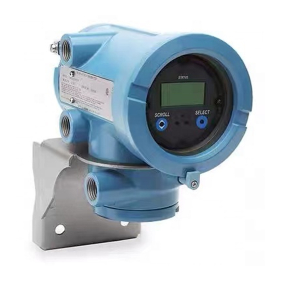
Page 20: Using The Optical Switches
Using the Transmitter Display Using the optical switches optical switches are used to navigate the transmitter display. To activate an Scroll Select optical switch, touch the glass in front of the optical switch or move your finger over the optical switch close to the glass. -
Page 21: Display Menus
Using the Transmitter Display Auto Scroll may or may not be enabled: • If Auto Scroll is enabled, each configured display variable will be shown for the number of seconds specified for Scroll Rate. At any time, you can interrupt the automatic scrolling (e.g., to control the display manually) by activating either optical switch. -
Page 22: Entering Floating-Point Values With The Display
Using the Transmitter Display If a password is required, the word CODE? appears at the top of the password screen. Enter the digits of the password one at a time by using to choose a number and to move to the next Scroll Select digit. - Page 23 Using the Transmitter Display To change from decimal to exponential notation (see Figure 2-3): until the rightmost digit is flashing. Select , then . The display changes to provide two spaces for entering the exponent. Scroll Select 3. To enter the exponent: until the desired digit is flashing.
- Page 24 Micro Motion Series 1000 and Series 2000 Transmitters...
-
Page 25: Connecting With Prolink Ii Or Pocket Prolink Software
Chapter 3 Connecting with ProLink II or Pocket ProLink Software Overview ProLink II is a Windows-based configuration and management tool for Micro • Model 1500 AN Motion transmitters. It provides complete access to transmitter functions and data. • Model 1700 AN Pocket ProLink is a version of ProLink II that runs on a Pocket PC. -
Page 26: Prolink Ii Configuration Upload/Download
Connecting with ProLink II or Pocket ProLink Software ProLink II configuration upload/download ProLink II provides a configuration upload/download function which allows you to save configuration sets to your PC. This allows: • Easy backup and restore of transmitter configuration • Easy replication of configuration sets Micro Motion recommends that all transmitter configurations be downloaded to a PC as soon as the configuration is complete. -
Page 27: Connecting To The Service Port
Connecting with ProLink II or Pocket ProLink Software 3.4.1 Connecting to the service port To connect to the service port, which is located in the non-intrinsically safe power • Model 1700 AN supply compartment (see Figure 3-1): • Model 1700 IS •... -
Page 28: Connecting To The Rs-485 Terminals Or An Rs-485 Network
Connecting with ProLink II or Pocket ProLink Software Figure 3-1 Service port connections to Model 1700 or 2700 Model 1700 or 2700 transmitter terminal compartment RS-485/B 25-pin to 9-pin serial port RS-485/A adapter (if necessary) RS-485 to RS-232 Service port signal converter 5. - Page 29 Connecting with ProLink II or Pocket ProLink Software Figure 3-2 RS-485 terminal connections to Model 1700 or 2700 AN 25-pin to 9-pin serial port Model 1700 or 2700 transmitter adapter (if necessary) terminal compartment (transmitters with analog outputs RS-485 to RS-232 option boards only) signal converter Figure 3-3...
-
Page 30: Connecting To The Primary Ma Output Terminals Or To A Hart Multidrop Network
Connecting with ProLink II or Pocket ProLink Software 10. If an error message appears: a. Swap the leads and try again. b. You may be using incorrect connection parameters. Ensure you are using the correct COM port. Connect using the service port and check the RS-485 configuration. If required, change the configuration or change your RS-485 connection parameters to match the existing configuration. - Page 31 Connecting with ProLink II or Pocket ProLink Software Figure 3-4 HART/Bell 202 connections to Model 1700/2700 AN or Model 2700 CIO 1 (+) Model 1700/2700 AN 2 (–) Model 2700 CIO See Step 5 DCS or See Step 5 See Step 5 Figure 3-5 HART/Bell 202 connections to Model 1700/2700 IS Primary mA output terminals...
- Page 32 Connecting with ProLink II or Pocket ProLink Software 5. Add resistance as required. The Viator HART interface must be connected across a resistance of 250–600 Ω. In addition, if you are using an IS transmitter, the primary mA output requires an external power supply with a minimum of 250 Ω...
-
Page 33: Connecting From A Pc To A Model 1500 Or Model 2500 Transmitter
Connecting with ProLink II or Pocket ProLink Software 12. If an error message appears: a. You may be using incorrect connection parameters. Ensure you are using the correct COM port. If you are unsure of the transmitter’s address, use the button in the Poll Connect... - Page 34 Connecting with ProLink II or Pocket ProLink Software Figure 3-7 RS-485 terminal connections to Model 1500 or 2500 RS-485/B RS-485/A 25-pin to 9-pin serial port RS-485 to RS-232 adapter (if necessary) signal converter Figure 3-8 RS-485 network connections to Model 1500 or 2500 RS-485/B RS-485/A DCS or PLC...
- Page 35 Connecting with ProLink II or Pocket ProLink Software 5. Start ProLink II. Choose Connection > Connect to Device . In the screen that appears, specify connection parameters appropriate to your connection type: • Service port mode – Immediately after the transmitter is powered up, terminals 33 and 34 are available in service port mode for 10 seconds.
-
Page 36: Hart/Bell 202 Connections
Connecting with ProLink II or Pocket ProLink Software 3.5.2 HART/Bell 202 connections CAUTION Connecting a HART device to the transmitter’s primary mA output terminals could cause transmitter output error. If the primary mA output is being used for flow control, connecting a HART device to the output loop could cause the transmitter’s 4–20 mA output to change, which would affect flow control devices. -
Page 37: Prolink Ii Language
Connecting with ProLink II or Pocket ProLink Software 5. Click Connect 6. If an error message appears: a. Ensure that you are using the correct COM port. b. Check all the wiring between the PC and the transmitter. c. Increase or decrease the resistance. ProLink II language ProLink II can be configured for several different languages. - Page 38 Micro Motion Series 1000 and Series 2000 Transmitters...
-
Page 39: Connecting With The 275 Hart Communicator Or
Chapter 4 Connecting with the 275 HART Communicator or 375 Field Communicator Overview The 275 HART Communicator and the 375 Field Communicator are handheld • Model 1500 AN configuration and management tools for HART-compatible devices, including Micro • Model 1700 AN Motion transmitters. -
Page 40: Viewing The Device Descriptions
Connecting with the 275 HART Communicator or 375 Field Communicator Table 4-1 Communicator models, device descriptions, and transmitter support 275 HART Communicator 375 Field Communicator Transmitter Device description Support Device description Support Model 1500 AN Not available None 1500 Mass Flow Full Model 1700 AN 1000 Mass Flow... -
Page 41: Connecting To A Transmitter
Connecting with the 275 HART Communicator or 375 Field Communicator Note: This procedure allows you to use the device description for the Model 2700 transmitter with the configurable input/outputs option board. You will not be able to configure the RS-485 parameters using this device description. - Page 42 Connecting with the 275 HART Communicator or 375 Field Communicator 3. The Communicator must be connected across a resistance of 250–600 Ω. Add resistance to the connection. See Figure 4-1. Figure 4-1 Connecting to communication terminals – Model 1700/2700 transmitters VDC (IS transmitters only) –...
-
Page 43: Connecting To A Multidrop Network
Connecting with the 275 HART Communicator or 375 Field Communicator 4.3.2 Connecting to a multidrop network The Communicator can be connected to any point in a multidrop network. See Figure 4-3. Ω Note: The Communicator must be connected across a resistance of 250–600 . - Page 44 Micro Motion Series 1000 and Series 2000 Transmitters...
-
Page 45: Flowmeter Startup
Chapter 5 Flowmeter Startup Overview This chapter describes the procedures you should perform the first time you install the flowmeter. Performing these steps will help verify that all the flowmeter components are installed and wired correctly. It is usually necessary to perform some additional first-time configuration of the transmitter, which is described in Chapter 6. -
Page 46: Applying Power
Flowmeter Startup Applying power Before you apply power to the flowmeter, close and tighten all housing covers. WARNING Operating the flowmeter without covers in place creates electrical hazards that can cause death, injury, or property damage. Make sure safety barrier partition and covers for the field-wiring, circuit board compartments, electronics module, and housing are all in place before applying power to the transmitter. -
Page 47: Performing A Loop Test
Flowmeter Startup Performing a loop test A loop test is a means to: • Verify that analog outputs (mA and frequency) are being sent by the transmitter and received accurately by the receiving devices • Determine whether or not you need to trim the mA outputs •... -
Page 48: Trimming The Milliamp Outputs
Flowmeter Startup Trimming the milliamp outputs Trimming the mA output creates a common measurement range between the transmitter and the device that receives the mA output. For example, a transmitter might send a 4 mA signal that the receiving device reports incorrectly as 3.8 mA. If the transmitter output is trimmed correctly, it will send a signal appropriately compensated to ensure that the receiving device actually indicates a 4 mA signal. -
Page 49: Zeroing The Flowmeter
Flowmeter Startup Zeroing the flowmeter Zeroing the flowmeter establishes the flowmeter’s point of reference when there is no flow. The meter was zeroed at the factory, and should not require a field zero. However, you may wish to perform a field zero to meet local requirements or to confirm the factory zero. -
Page 50: Zero Procedure
Flowmeter Startup 5.5.2 Zero procedure To zero the flowmeter, refer to the procedures shown in Figures 5-3 through 5-6. Note the following: • The zero button is available only on Model 1500 or Model 2500 transmitters. It is located on the front panel of the transmitter. - Page 51 Flowmeter Startup Figure 5-5 Display menu – Flowmeter zero procedure Scroll and Select simultaneously for 4 seconds Scroll OFF-LINE MAINT Select Scroll CAL ZERO RESTORE ZERO EXIT Scroll Scroll Select Select ZERO/YES? xxxx CUR Z Select Scroll …………………. yyyy FAC Z Scroll CAL FAIL CAL PASS...
- Page 52 Flowmeter Startup Figure 5-6 Communicator – Flowmeter zero procedure On-Line Menu > 3 Diag/Service > 3 Calibration 1 Auto zero Modify zero time if required Perform auto zero Calibration in Progress message Auto Zero Failed Auto Zero Complete Troubleshoot Micro Motion Series 1000 and Series 2000 Transmitters...
-
Page 53: Required Transmitter Configuration
Chapter 6 Required Transmitter Configuration Overview This chapter describes the configuration procedures that are usually required when a transmitter is installed for the first time. The procedures in this chapter should be performed in the order shown in Figure 6-1. Figure 6-1 Required configuration procedures in order Characterize the... -
Page 54: Characterizing The Flowmeter
Required Transmitter Configuration This chapter provides basic information and procedural flowcharts for each configuration step. For more details about how to perform each procedure, see the flowcharts for your transmitter and communication tool, provided in the appendices to this manual. Default values and ranges for the parameters described in this chapter are provided in Appendix A. - Page 55 Required Transmitter Configuration Table 6-1 Sensor calibration parameters Sensor type Parameter T-Series Other ✓ ✓ ✓ ✓ ✓ ✓ ✓ ✓ ✓ ✓ ✓ ✓ Temp coeff (DT) ✓ Flowcal ✓ FCF and FT ✓ ✓ ✓ ✓ ✓ DFQ1 ✓...
- Page 56 Required Transmitter Configuration Figure 6-3 Sample calibration tags – T-Series sensors Newer tag Older tag Density calibration factors If your sensor tag does not show a D1 or D2 value: • For D1, enter the Dens A or D1 value from the calibration certificate. This value is the line-condition density of the low-density calibration fluid.
-
Page 57: How To Characterize
Required Transmitter Configuration 6.2.3 How to characterize To characterize the flowmeter: • Refer to Figure 6-4. • Ensure that the correct sensor type is configured. • Set required parameters, as listed in Table 6-1. Figure 6-4 Characterizing the flowmeter ProLink II Communicator P r o L in k II C o m m u n ic a to r... -
Page 58: Mass Flow Units
Required Transmitter Configuration Figure 6-5 Configuring measurement units ProLink II Communicator Display ProLink > Off-line maint > On-Line Menu > Off-line config Configuration Detailed Setup Flow Units Config field dev var Mass Density Flow Vol (or GSV) Temperature Density Density Pressure Temperature Temperature... -
Page 59: Volume Flow Units
Required Transmitter Configuration Table 6-2 Mass flow measurement units continued Mass flow unit Display ProLink II Communicator Unit description LT/H lTon/hr LTon/h Long tons (2240 pounds) per hour LT/D lTon/day LTon/d Long tons (2240 pounds) per day SPECL special Spcl Special unit (see Section 8.5) 6.4.2 Volume flow units... - Page 60 Required Transmitter Configuration Table 6-3 Volume flow measurement units – Liquids continued Volume flow unit Display ProLink II Communicator Unit description UKGPM Imp gal/min Impgal/min Imperial gallons per minute UKGPH Imp gal/hr Impgal/h Imperial gallons per hour UKGPD Imp gal/day Impgal/d Imperial gallons per day BBL/S...
-
Page 61: Density Units
Required Transmitter Configuration Table 6-4 Volume flow measurement units – Gas continued Volume flow unit Display ProLink II Communicator Unit description SLPH SLPH Not available Standard liter per hour SLPD SLPD Not available Standard liter per day SPECL special Spcl Special unit (see Section 8.5) 6.4.3 Density units... -
Page 62: Pressure Units
Required Transmitter Configuration 6.4.5 Pressure units The flowmeter does not measure pressure, but the transmitter can poll an external pressure measurement device. The default pressure measurement unit is . See Table 6-7 for a complete list of pressure measurement units. It is not necessary to match units between the transmitter and the external pressure device –... -
Page 63: Configuring The Discrete Input
Required Transmitter Configuration Configuring the discrete input See the Configuration and Use Manual Supplement for your transmitter for information and instructions on configuring the discrete input. Establishing a meter verification baseline Note: This procedure applies only if your transmitter is connected to an enhanced core processor and you have ordered the meter verification application. - Page 64 Micro Motion Series 1000 and Series 2000 Transmitters...
-
Page 65: Using The Transmitter
Chapter 7 Using the Transmitter Overview This chapter describes how to use the transmitter in everyday operation. The following topics and procedures are discussed: • Special applications on your transmitter (see Section 7.2) • Viewing process variables (see Sections 7.4) •... -
Page 66: Recording Process Variables
Using the Transmitter Recording process variables Micro Motion suggests that you make a record of the process variables listed below, under normal operating conditions. This will help you recognize when the process variables are unusually high or low, and may help in fine-tuning transmitter configuration. Record the following process variables: •... -
Page 67: With A Communicator
Using the Transmitter 7.4.3 With a Communicator To view process variables with a Communicator: 1. Press 2. Scroll through the list of process variables by pressing Down Arrow 3. Press the number corresponding to the process variable you wish to view, or highlight the process variable in the list and press Right Arrow Viewing transmitter status and alarms... - Page 68 Using the Transmitter Figure 7-1 Display status LED Status LED Select optical switch Scroll optical switch Table 7-2 Priorities reported by the Model 1700/2700 status LED Status LED state Alarm priority Green No alarm – normal operating mode Flashing green Unacknowledged corrected condition Yellow Acknowledged low severity alarm...
-
Page 69: Using Prolink Ii
Using the Transmitter 7.5.3 Using ProLink II ProLink II provides two ways to view alarm information: • Choose . This window shows the current status of all possible alarms, ProLink > Status independent of configured alarm severity. The alarms are divided into three categories: Critical, Informational, and Operational. -
Page 70: Using The Totalizers And Inventories
Using the Transmitter 5. If you want to acknowledge a single alarm: until the alarm you want to acknowledge appears. Scroll Select . The word ALARM begins to alternate with the word to acknowledge the alarm. Select 6. If you want to acknowledge another alarm, go to Step 3. 7. -
Page 71: Controlling Totalizers And Inventories
Using the Transmitter 2. To view inventory values, Scroll until the word TOTAL appears and: • For the mass inventory, the word (Mass Inventory) begins to alternate with the MASSI units of measure • For the volume inventory, the word LVOLI (Line Volume Inventory) begins to alternate with the units of measure... - Page 72 Using the Transmitter Table 7-3 Totalizer and inventory control methods Function name Communicator ProLink II Display Stop all totalizers and inventories (mass, volume, ED, and API) Start all totalizers and inventories (mass, volume, ED, and API) Reset mass totalizer only Reset volume totalizer only Reset API totalizer only Reset ED totalizer only...
- Page 73 Using the Transmitter Figure 7-3 Controlling totalizers and inventories with the display Process variable display Scroll API total (1)(2) Mass total Volume total Scroll Scroll ED total (1)(2) Select E1--SP EXIT Scroll Scroll STOP/START (4)(5) Scroll RESET (6)(7) Scroll E2--SP Select Select STOP/START YES?
- Page 74 Micro Motion Series 1000 and Series 2000 Transmitters...
-
Page 75: Chapter 8 Optional Configuration
Chapter 8 Optional Configuration Overview This chapter describes transmitter configuration parameters that may or may not be used, depending on your application requirements. For required transmitter configuration, see Chapter 6. For information about how to perform the procedures described in this chapter, see the flowcharts for your transmitter and communication tool, provided in the appendices to this manual. - Page 76 Optional Configuration Table 8-1 Configuration map Transmitter 1500 1700 2500 2700 Topic Subtopic Section ✓ ✓ ✓ ✓ ✓ ✓ ✓ Gas standard volume measurement ✓ ✓ ✓ ✓ ✓ ✓ ✓ Special measurement units ✓ ✓ ✓ ✓ Petroleum measurement application (API feature)
-
Page 77: Configuring Standard Volume Flow Measurement For Gas
Optional Configuration Configuring standard volume flow measurement for gas Special functionality is provided for measuring the standard volume flow of gases. • Model 1500 AN ProLink II is required to access this functionality. Other tools provide only limited • Model 1700 AN •... -
Page 78: Creating Special Measurement Units
Optional Configuration 4. If your gas is not listed, you must describe its properties. a. Select the radio button. Enter Other Gas Property b. Select the method that you will use to describe its properties: Molecular Weight Specific , or Gravity Compared to Air Density c. -
Page 79: Special Measurement Unit Procedure
Optional Configuration The preceding terms are related by the following formula: x BaseUnit(s) y SpecialUnit(s) x BaseUnit(s) ConversionFactor -------------------------------------------- - y SpecialUnit(s) 8.5.2 Special measurement unit procedure To create a special measurement unit: 1. If necessary, set Volume Flow Type to match the type of special measurement unit you will create. -
Page 80: Configuring The Petroleum Measurement Application (Api Feature)
Optional Configuration Configuring the petroleum measurement application (API feature) The API parameters determine the values that will be used in API-related • Model 2500 CIO calculations. The API parameters are available only if the petroleum measurement • Model 2700 AN application is enabled on your transmitter. - Page 81 Optional Configuration API reference tables Reference tables are organized by reference temperature, CTL derivation method, liquid type, and density unit. The table selected here controls all the remaining options. • Reference temperature: If you specify a 5x, 6x, 23x, or 24x table, the default reference temperature is 60 °F, and cannot be changed.
-
Page 82: Configuring Cutoffs
Optional Configuration Table 8-3 API reference temperature tables continued Density unit and range derivation Table method Base temperature Degrees API Base density Relative density Reference temperature Supports Method 2 60 °F, non-configurable 60 °F Degrees API Method 2 60 °F, non-configurable 60 °F Relative density Method 2... -
Page 83: Cutoffs And Volume Flow
Optional Configuration 8.7.1 Cutoffs and volume flow If you are using liquid volume flow units ( is set to Vol Flow Type Liquid • The density cutoff is applied to the volume flow calculation. Accordingly, if the density drops below its configured cutoff value, the volume flow rate will go to zero. •... -
Page 84: Damping And Volume Measurement
Optional Configuration 8.8.1 Damping and volume measurement When configuring damping values, note the following: • Liquid volume flow is derived from mass and density measurements; therefore, any damping applied to mass flow and density will affect liquid volume measurement. • Gas standard volume flow is derived from mass flow measurement, but not from density measurement. -
Page 85: Effects Of Special Mode
Optional Configuration 8.9.1 Effects of Special mode In Special mode: • Not all process variables are updated. The process variables listed below are always updated: Mass flow Volume flow Gas standard volume flow Density Temperature Drive gain LPO amplitude Status (contains Event 1 and Event 2) Raw tube frequency Mass total Volume total... -
Page 86: Configuring The Flow Direction Parameter
Optional Configuration 8.10 Configuring the flow direction parameter The flow direction parameter controls how the transmitter reports flow rate and how • Model 1500 AN flow is added to or subtracted from the totalizers, under conditions of forward flow, • Model 1700 AN reverse flow, or zero flow. - Page 87 Optional Configuration Figure 8-2 Effect of flow direction on mA outputs: 4mA value < 0 –x –x –x Reverse Forward Reverse Forward Reverse Forward flow flow flow flow flow flow Zero flow Zero flow Zero flow Flow direction parameter: Flow direction parameter: Flow direction parameter: •...
- Page 88 Optional Configuration Example 2 Configuration: • Flow direction = Reverse • mA output: 4 mA = 0 g/s; 20 mA = 100 g/s (See the second graph in Figure 8-1.) As a result: • Under conditions of forward flow or zero flow, the mA output level is 4 mA.
-
Page 89: Configuring Events
Optional Configuration Table 8-6 Effect of flow direction on frequency output, discrete output, totalizers, and digital communications Forward flow Frequency Flow values via Flow direction value output Discrete output Flow totals digital comm. Forward Increase Increase Positive Reverse 0 Hz No change Positive Bidirectional... -
Page 90: Configuring Slug Flow Limits And Duration
Optional Configuration 1. Referring to the totalizer management flowchart in Figure 7-3, Scroll to the appropriate display screen: • To change the setpoint for an event defined on mass total, Scroll to the mass total screen. • To change the setpoint for an event defined on volume total, to the volume total Scroll screen. -
Page 91: Configuring Fault Handling
Optional Configuration Note: If slug flow duration is set to 0, the mass flow rate will be forced to 0 as soon as slug flow is detected. 8.13 Configuring fault handling There are three ways that the transmitter can report faults: •... - Page 92 Optional Configuration Table 8-8 Status alarms and severity levels continued Communicator message Default Affected by Alarm code ProLink II message severity Configurable fault timeout A003 Sensor Not Responding (No Tube Interrupt) Fault Sensor Failure A004 Temperature Sensor Out-of-Range Fault Temperature Sensor Failure A005 Input Over-Range Fault...
- Page 93 Optional Configuration Table 8-8 Status alarms and severity levels continued Communicator message Default Affected by Alarm code ProLink II message severity Configurable fault timeout A024 (E)EPROM Program Corrupt (Core Processor) Fault (E)EPROM Program Corrupt (CP) A025 Protected Boot Sector Fault Fault Protected Boot Sector Fault (CP) A026...
- Page 94 Optional Configuration Table 8-8 Status alarms and severity levels continued Communicator message Default Affected by Alarm code ProLink II message severity Configurable fault timeout A108 Event #1 Triggered Info Event 1 Triggered A109 Event #2 Triggered Info Event 2 Triggered A110 Info Frequency Output Saturated...
-
Page 95: Fault Timeout
Optional Configuration 8.13.2 Fault timeout If a fault is detected, the transmitter always sets the “alarm active” status bit immediately. Fault actions for the transmitter outputs and digital communications may be implemented immediately or may be delayed until the fault timeout expires. During the fault timeout, outputs continue to report their last measured value. -
Page 96: Changing The Scroll Rate
Optional Configuration Table 8-9 Display parameters continued Parameter Enabled Disabled Acknowledge all Operators are able to acknowledge all current Operators must acknowledge alarms alarms alarms at once. individually. Backlight on/off Display backlight is on. Display backlight is off. Alarm screen Operators must enter the display password to Operators can access the alarm menu without password... -
Page 97: Configuring Digital Communications
Optional Configuration 8.15 Configuring digital communications See the Configuration and Use Manual Supplement for your transmitter for information and instructions on configuring digital communications parameters. 8.16 Configuring device settings The device settings are used to describe the flowmeter components. Table 8-10 lists •... -
Page 98: Configuring Write-Protect Mode
Optional Configuration 8.18 Configuring write-protect mode When the transmitter is in write-protect mode, the configuration data stored in the • Model 1500 AN transmitter and core processor cannot be changed until write-protect mode is • Model 1700 AN disabled. • Model 1700 IS •... -
Page 99: Pressure Compensation, Temperature Compensation, And Polling
Chapter 9 Pressure Compensation, Temperature Compensation, and Polling Overview This chapter describes the following procedures: • Configuring pressure compensation (see Section 9.2) • Configuring external temperature compensation (see Section 9.3) • Configuring polling (see Section 9.4) Note: All ProLink II procedures provided in this section assume that your computer is already connected to the transmitter and you have established communication. -
Page 100: Pressure Correction Factors
Pressure Compensation, Temperature Compensation, and Polling 9.2.2 Pressure correction factors When configuring pressure compensation, you must provide the flow calibration pressure – the pressure at which the flowmeter was calibrated (which therefore defines the pressure at which there will be no effect on the calibration factor). Refer to the calibration document shipped with your sensor. -
Page 101: External Temperature Compensation
Pressure Compensation, Temperature Compensation, and Polling Figure 9-2 Configuring pressure compensation with the Communicator Set pressure measurement unit Configure pressure compensation On-Line Menu > On-Line Menu > Detailed Setup Detailed Setup Config field dev var Charize Sensor Pressure Pressure Comp Enter Pressure unit Enable pressure comp Send... - Page 102 Pressure Compensation, Temperature Compensation, and Polling Note: If your core processor is v2.1 or earlier, and you configure the transmitter for external temperature compensation, the temperature value from the compensation procedure will replace the sensor value in all calculations that require temperature data. If your core processor is v2.2 or later, the temperature value from the compensation procedure is used only for enhanced density and petroleum measurement calculations.
-
Page 103: Configuring Polling
Pressure Compensation, Temperature Compensation, and Polling Figure 9-4 Configuring external temperature compensation with the Communicator Configure temperature compensation Set temperature measurement unit On-Line Menu > On-Line Menu > Detailed Setup Detailed Setup Config field dev var Charize Sensor Temperature Ext temp Enter Temp unit Enable ext temp Poll? - Page 104 Pressure Compensation, Temperature Compensation, and Polling Figure 9-5 Configuring polling with ProLink II Polling for pressure Polling for temperature ProLink > ProLink > Configuration > Configuration > Temperature Set External temperature to 32 °F (0 °C) Apply Polled variables Polled variable 1 Polled variable 2 (1) Choose Primary if the external Specify Polling control...
- Page 105 Pressure Compensation, Temperature Compensation, and Polling Figure 9-6 Configuring polling with the Communicator Polling for pressure Polling for temperature On-Line Menu > On-Line Menu > 5 Detailed Setup 5 Detailed Setup 1 Charize Sensor 1 Charize Sensor 9 Ext temp Set Static temperature to 32 °F (0 °C) Send...
- Page 106 Micro Motion Series 1000 and Series 2000 Transmitters...
-
Page 107: Chapter 10 Measurement Performance
Chapter 10 Measurement Performance 10.1 Overview This chapter describes the following procedures: • Meter verification – see Section 10.3 • Meter validation and adjusting meter factors – see Section 10.4 • Density calibration – see Section 10.5 • Temperature calibration – see Section 10.6 This chapter provides basic information and procedural flowcharts for each step. -
Page 108: Meter Verification
Measurement Performance 10.2.1 Meter verification Meter verification evaluates the structural integrity of the sensor tubes by comparing current tube stiffness to the stiffness measured at the factory. Stiffness is defined as the load per unit deflection, or force divided by displacement. Because a change in structural integrity changes the sensor’s response to mass and density, this value can be used as an indicator of measurement performance. -
Page 109: Meter Validation And Meter Factors
Measurement Performance Table 10-2 Comparison of meter verification features and functions: original version vs. Smart Meter Verification continued Meter verification application Feature or function Original version Smart Meter Verification Result data on display Pass/Fail/Abort for current test For all results stored on transmitter: •... -
Page 110: Comparison And Recommendations
Measurement Performance Density and temperature calibration require two data points (low and high) and an external measurement for each. Calibration produces a change in the offset and/or the slope of the line that represents the relationship between process density and the reported density value, or the relationship between process temperature and the reported temperature value. -
Page 111: Performing Meter Verification
Measurement Performance Micro Motion recommends obtaining the meter verification transmitter option and performing meter verification on a regular basis. 10.3 Performing meter verification Note: To use meter verification, the transmitter must be paired with an enhanced core processor, and the meter verification option must be purchased for the transmitter. 10.3.1 Preparing for the meter verification test Process fluid and process conditions... - Page 112 Measurement Performance Note: If you start a meter verification test from ProLink II or the Communicator, the transmitter display shows the following message: SENSOR VERFY/x% Figure 10-1 Meter verification test, original version – ProLink II Tools > Meter Verification > Structural Integrity Method Verify configuration View previous test data...
- Page 113 Measurement Performance Figure 10-2 Meter verification test, original version – Display Scroll and Select simultaneously for 4 seconds Scroll OFF-LINE MAINT Select Scroll SENSOR VERFY Select OUTPUTS Select Scroll Choose output setting SENSOR EXIT STOP MSMT/YES? Select Scroll UNSTABLE FLOW .
-
Page 114: Running Smart Meter Verification
Measurement Performance Figure 10-3 Meter verification test, original version – Communicator On-Line Menu > 3 Diag/Service > 3 Calibration > 3 Meter verification Choose output setting Set stiffness setpoint Meter verification completed: x% Meter verification Meter verification Meter verification UNSTABLE FLOW PASS CAUTION FAILED... - Page 115 Measurement Performance Figure 10-4 Smart Meter Verification test – ProLink II Tools > Meter Verification > Run Meter Verification Verify configuration View Previous Results parameters Next Enter descriptive data (optional) Next Configuration Changed or Zero Changed? View details (optional) Select output behavior Start Meter Verification --------------------- Fail...
- Page 116 Measurement Performance Figure 10-5 Smart Meter Verification top-level menu – Display Scroll and Select simultaneously for 4 seconds Scroll ENTER METER VERFY Select RUN VERFY RESULTS READ SCHEDULE VERFY EXIT Scroll Scroll Scroll Select Select Select Scroll Select Micro Motion Series 1000 and Series 2000 Transmitters...
- Page 117 Measurement Performance Figure 10-6 Smart Meter Verification test – Display RUN VERFY Select OUTPUTS EXIT Scroll Select CONTINUE MEASR FAULT LAST VALUE EXIT Scroll Scroll Scroll Select Select Select ARE YOU SURE/YES? Select ....x% Select SENSOR ABORT/YES? Scroll...
- Page 118 Measurement Performance Figure 10-7 Smart Meter Verification test – Communicator Online > Online > 1 Overview > 3 Service Tools > 3 Shortcuts > 4 Maintenance > 6 Meter Verification 1 Routine Maintenance > 3 Meter Verification 1 Run Meter Verification 2 View Test Results 3 Schedule Meter Verification Select Output Behavior...
-
Page 119: Reading And Interpreting Meter Verification Test Results
Measurement Performance 10.3.4 Reading and interpreting meter verification test results Pass/Fail/Abort When the meter verification test is completed, the result is reported as Pass, Fail or Caution (depending on whether you are using the display, the Communicator, or ProLink II), or Abort: •... - Page 120 Measurement Performance Detailed test data with ProLink II For each test, the following data is stored on the transmitter: • Powered-on hours at the time of the test (Smart Meter Verification) • Test result • Stiffness of the left and right pickoffs, shown as percentage variation from the factory value. If the test aborted, 0 is stored for these values.
- Page 121 Measurement Performance Figure 10-8 Test result chart Initiated from ProLink II Initiated from the display or other tool The test result chart shows the results for all tests in the ProLink II database, plotted against the specification uncertainty limit. The inlet stiffness and the outlet stiffness are plotted separately. This helps to distinguish between local and uniform changes to the sensor tubes.
- Page 122 Measurement Performance Note the following: • The test result chart may not show all test results, and test counters may not be continuous. ProLink II stores information about all tests initiated from ProLink II and all tests available on the transmitter when the test database is synchronized. However, the transmitter stores only the twenty most recent test results.
- Page 123 Measurement Performance Figure 10-9 Meter verification test data – Display RESULTS READ Select RUNCOUNT x Select Scroll Pass Result type Abort Fail xx HOURS xx HOURS xx HOURS Select Select Select PASS CAUTION Abort Type Select Select Select xx L STF% xx L STF% Select Select...
- Page 124 Measurement Performance Detailed test data with the Communicator Note: Requires Smart Meter Verification. No detailed test data is available with the original version of the meter verification application. For each Smart Meter Verification test, the following data is stored on the transmitter: •...
-
Page 125: Setting Up Automatic Or Remote Execution Of The Meter Verification Test
Measurement Performance Figure 10-10 Meter verification test data – Communicator Online > Online > 1 Overview > 3 Service Tools > 3 Shortcuts > 4 Maintenance > 6 Meter Verification 1 Routine Maintenance > 3 Meter Verification 1 Run Meter Verification 2 View Test Results 3 Schedule Meter Verification 1 Run Counter... - Page 126 Measurement Performance In addition, if your transmitter has a discrete input, you can configure the discrete input to initiate a Smart Meter Verification test remotely. You can use these methods in any combination. For example, you can specify that a Smart Meter Verification test will be executed three hours from now, every 24 hours starting now, every time a specific discrete event occurs, and every time the discrete input is activated.
- Page 127 Measurement Performance Figure 10-11 Smart Meter Verification scheduler – Display SCHEDULE VERFY Select Schedule set? SCHED IS OFF TURN OFF SCHED/YES? Scroll Scroll Select Schedule deleted HOURS LEFT Scroll Select xx HOURS Select SET NEXT SET RECUR EXIT Scroll Scroll Select Select Scroll...
-
Page 128: Performing Meter Validation
Measurement Performance Figure 10-12 Smart Meter Verification scheduler – Communicator Online > Online > 1 Overview > 3 Service Tools > 3 Shortcuts > 4 Maintenance > 6 Meter Verification 1 Routine Maintenance > 3 Meter Verification 1 Run Meter Verification 2 View Test Results 3 Schedule Meter Verification 1 Next Run... -
Page 129: Performing Density Calibration
Measurement Performance 10.5 Performing density calibration Density calibration includes the following calibration points: • All sensors: D1 calibration (low-density) D2 calibration (high-density) • T-Series sensors only: D3 calibration (optional) D4 calibration (optional) For T-Series sensors, the optional D3 and D4 calibrations could improve the accuracy of the density measurement. -
Page 130: Density Calibration Procedures
Measurement Performance For D4 density calibration, the D4 fluid must meet the following requirements: • Minimum density of 0.6 g/cm • Minimum difference of 0.1 g/cm between the density of the D4 fluid and the density of the D3 fluid. The density of the D4 fluid must be greater than the density of the D3 fluid. •... - Page 131 Measurement Performance Figure 10-14 D1 and D2 density calibration – Communicator D1 calibration D2 calibration Close shutoff valve Fill sensor with D1 fluid Fill sensor with D2 fluid downstream from sensor 3 Diag/Service > On-Line Menu > 3 Calibration > 3 Diag/Service >...
- Page 132 Measurement Performance Figure 10-15 D3 or D3 and D4 density calibration – ProLink II D3 calibration D4 calibration Close shutoff valve Fill sensor with D3 fluid Fill sensor with D4 fluid downstream from sensor ProLink Menu > ProLink Menu > Calibration >...
-
Page 133: Performing Temperature Calibration
Measurement Performance Figure 10-16 D3 or D3 and D4 density calibration – Communicator D3 calibration D4 calibration Close shutoff valve Fill sensor with D3 fluid Fill sensor with D4 fluid downstream from sensor 3 Diag/Service > On-Line Menu > 3 Calibration > 3 Diag/Service >... - Page 134 Measurement Performance Figure 10-17 Temperature calibration – ProLink II Temperature Offset calibration Temperature Slope calibration Fill sensor with low- Fill sensor with high- temperature fluid temperature fluid Wait until sensor achieves Wait until sensor achieves thermal equilibrium thermal equilibrium ProLink Menu > ProLink Menu >...
-
Page 135: Chapter 11 Custody Transfer
Chapter 11 Custody Transfer 11.1 Overview The following transmitters can be ordered with a custody transfer configuration: • Model 2700 AN • Model 2700 CIO • Model 2500 CIO A transmitter is appovable for custody transfer if it matches the following model code pattern: 2700(R, C, or B)**(A, B, or C)****W* 2500********W* See Section 1.3.1 for information about how to interpret transmitter model codes. -
Page 136: Special Restrictions When Using Custody Transfer Transmitters
Custody Transfer 11.4 Special restrictions when using custody transfer transmitters Some of the transmitter’s functionality is restricted when it is ordered with a custody transfer configuration. These restrictions include: • Restricted I/O – The inputs/outputs of your transmitter may be disabled or their use may be restricted. -
Page 137: Transmitter Outputs In Security Breach Mode
Custody Transfer Note: If the LED blinking option is disabled, the status LED will not flash to indicate security breach mode. In security breach mode, it is possible to perform a number of actions, including zeroing, loop test, output trim, resetting totalizers (not inventories), and basic configuration. These functions (except resetting totalizers) will become unavailable after the transmitter has been secured. -
Page 138: Transmitter Outputs In Secure Mode
Custody Transfer 11.7.1 Transmitter outputs in secure mode The following outputs are approved in secure mode: • Frequency output for the transmission of volume or mass information, and for fault indication (available only on Models 2700 CIO and 2500 CIO) •... -
Page 139: Chapter 12 Troubleshooting
Chapter 12 Troubleshooting 12.1 Overview This chapter describes guidelines and procedures for troubleshooting the meter. The information in this chapter will enable you to: • Categorize the problem • Determine whether you are able to correct the problem • Take corrective measures (if possible) •... -
Page 140: Micro Motion Customer Service
Troubleshooting Table 12-1 Troubleshooting topics and locations continued Section Topic Section 12.11 Transmitter status LED Section 12.12 Status alarms Section 12.13 Checking process variables Section 12.14 Diagnosing wiring problems Section 12.14.1 Checking the power supply wiring Section 12.14.2 Checking the sensor-to-transmitter wiring Section 12.14.3 Checking for RF interference Section 12.14.4... -
Page 141: Zero Or Calibration Failure
Troubleshooting 12.6 Zero or calibration failure If a zero or calibration procedure fails, the transmitter will send a status alarm indicating the cause of failure. See Section 12.12 for specific remedies for status alarms indicating calibration failure. 12.7 Fault conditions If the analog or digital outputs indicate a fault condition (by transmitting a fault indicator), determine the exact nature of the fault by checking the status alarms with a Communicator or ProLink II software, or the display if available on your transmitter. - Page 142 Troubleshooting Table 12-2 I/O problems and remedies continued Symptom Possible cause Possible remedy mA output < 4 mA Process condition below LRV Verify process. Change the LRV. Fault condition if fault indicator is set to Check the fault indicator settings to verify internal zero whether or not the transmitter is in a fault condition.
- Page 143 Troubleshooting Table 12-2 I/O problems and remedies continued Symptom Possible cause Possible remedy Constant mA output Non-zero HART address (multi-drop Set HART address to zero. See Section 12.19. communications) (primary mA output only) Output is fixed in a test mode Exit output from test mode.
-
Page 144: 12.10 Simulation Mode
Troubleshooting Table 12-2 I/O problems and remedies continued Symptom Possible cause Possible remedy FO phase on Channel C Wrong configuration setting FO mode must be set to Quadrature for phase to does not change with flow automatically track flow direction. direction (Config IO transmitters only) DI is fixed and does not... -
Page 145: 12.11 Transmitter Status Led
Troubleshooting 2. For mass flow: a. Specify the type of simulation you want: fixed value, triangular wave, or sine wave. b. Enter the required values. • If you specified fixed value simulation, enter a fixed value. • If you specified triangular wave or sine wave simulation, enter a minimum amplitude, maximum amplitude, and period. -
Page 146: 12.12 Status Alarms
Troubleshooting Table 12-4 Model 1700/2700 transmitter status reported by the status LED Status LED state Alarm priority Green No alarm – normal operating mode Flashing green Unacknowledged corrected condition Yellow Acknowledged low severity alarm Flashing yellow Unacknowledged low severity alarm Acknowledged high severity alarm Flashing red Unacknowledged high severity alarm... - Page 147 Troubleshooting Table 12-5 Status alarms and remedies continued Alarm code Communicator ProLink II software Possible remedy A005 Input Over-Range Input Overrange Check the test points. See Section 12.25. Check the sensor coils. See Section 12.27. Verify process. Make sure that the appropriate measurement unit is configured.
- Page 148 Troubleshooting Table 12-5 Status alarms and remedies continued Alarm code Communicator ProLink II software Possible remedy A016 Line RTD Overrange Line Temp Out-of-range Check the test points. See Section 12.25. Check the sensor coils. See Section 12.27. Check wiring to sensor. See Section 12.14.2. Make sure the appropriate sensor type is configured.
- Page 149 Troubleshooting Table 12-5 Status alarms and remedies continued Alarm code Communicator ProLink II software Possible remedy A027 Security Breach Security Breach Weights and Measures security seal has been broken. Alarm can be cleared by user, but authorized procedure is required to reestablish security.
- Page 150 Troubleshooting Table 12-5 Status alarms and remedies continued Alarm code Communicator ProLink II software Possible remedy A108 Event #1 Triggered Event 1 Triggered Be advised of alarm condition. If you believe the event has been triggered erroneously, verify the Event 1 settings. See Section 8.11.
-
Page 151: 12.13 Checking Process Variables
Troubleshooting Table 12-5 Status alarms and remedies continued Alarm code Communicator ProLink II software Possible remedy Density FD cal in Be advised that density calibration is in progress. progress Density 1st point cal in Be advised that density calibration is in progress. progress Density 2nd point cal in Be advised that density calibration is in progress. - Page 152 Troubleshooting Table 12-6 Process variables problems and possible remedies Symptom Cause Possible remedy Steady non-zero flow rate under Misaligned piping (especially in new Correct the piping. no-flow conditions installations) Open or leaking valve Check or correct the valve mechanism. Bad sensor zero Rezero the meter.
- Page 153 Troubleshooting Table 12-6 Process variables problems and possible remedies continued Symptom Cause Possible remedy Erratic non-zero flow rate when flow Output wiring problem Verify wiring between transmitter and is steady receiving device. See the installation manual for your transmitter. Problem with receiving device Test with another receiving device.
-
Page 154: 12.14 Diagnosing Wiring Problems
Troubleshooting Table 12-6 Process variables problems and possible remedies continued Symptom Cause Possible remedy Temperature reading significantly RTD failure Check for alarm conditions and follow different from process temperature troubleshooting procedure for indicated alarm. Verify “Use external temperature” configuration and disable if appropriate. See Section 9.3. -
Page 155: Checking The Sensor-To-Transmitter Wiring
Troubleshooting 5. Verify that the power supply wires are making good contact, and are not clamped to the wire insulation. 6. (Model 1700/2700 transmitters only) Inspect the voltage label on the inside of the field-wiring compartment. Verify that the voltage supplied to the transmitter matches the voltage specified on the label. -
Page 156: Checking The Hart Communication Loop
Troubleshooting 12.14.5 Checking the HART communication loop To check the HART communication loop: 1. Verify that the loop wires are connected as shown in the wiring diagrams in the transmitter installation manual. 2. Remove analog loop wiring. 3. Install a 250 Ω resistor across the primary mA output terminals. 4. -
Page 157: 12.16 Checking The Output Wiring And Receiving Device
3. Click on About ProLink Your AMS software must have Device Revisions 1 to 3. Contact Emerson Process Management. 12.16 Checking the output wiring and receiving device If you receive an inaccurate frequency or mA reading, there may be a problem with the output wiring or the receiving device. -
Page 158: 12.18 Checking Output Saturation
Troubleshooting If slug flow occurs: • Check process for cavitation, flashing, or leaks. • Change the sensor orientation. • Monitor density. • If desired, enter new slug flow limits (see Section 8.12). • If desired, increase slug duration (see Section 8.12). 12.18 Checking output saturation If an output variable exceeds the upper range limit or goes below the lower range limit, the applications platform produces an output saturation alarm. -
Page 159: 12.21 Checking The Upper And Lower Range Values
Troubleshooting 12.21 Checking the upper and lower range values A saturated mA output or incorrect mA measurement could indicate a faulty URV or LRV. Verify that the URV and LRV are correct and change them if necessary. See Section . 12.22 Checking the frequency output scale and method A saturated frequency output or an incorrect frequency measurement could indicate a faulty frequency output scale and/or method. -
Page 160: Obtaining The Test Points
Troubleshooting 12.25.1 Obtaining the test points You can obtain the test points with a Communicator or ProLink II software. With a Communicator To obtain the test points with a Communicator: 1. Select Diag/Service 2. Select Test Points 3. Select Drive a. -
Page 161: Excessive Drive Gain
Troubleshooting Table 12-7 Sensor pickoff values Sensor Pickoff value ELITE Model CMF sensors 3.4 mV peak-to-peak per Hz based on sensor flow tube frequency Model D, DL, and DT sensors 3.4 mV peak-to-peak per Hz based on sensor flow tube frequency Model F025, F050, F100 sensors 3.4 mV peak-to-peak per Hz based on sensor flow tube frequency Model F200 sensors (compact case) -
Page 162: Low Pickoff Voltage
Troubleshooting Table 12-9 Erratic drive gain causes and remedies Cause Possible remedy Wrong K1 characterization constant for sensor Re-enter the K1 characterization constant. See Section 6.2. Polarity of pick-off reversed or polarity of drive reversed Contact Micro Motion. See Section 12.3. Slug flow See Section 12.17. - Page 163 Troubleshooting 4. If you have an integral installation (Model 1700/2700 transmitters only): a. Loosen the four cap screws that fasten the transmitter to the base (see Figure B-9). b. Rotate the transmitter counter-clockwise so that the cap screws are in the unlocked position.
- Page 164 Troubleshooting Table 12-11 Standard core processor LED behavior, meter conditions, and remedies continued LED behavior Condition Possible remedy 3 rapid flashes, Sensor not recognized Check wiring between transmitter and sensor (9-wire remote followed by pause installation or remote core processor with remote transmitter installation).
-
Page 165: Core Processor Resistance Test (Standard Core Processor Only)
Troubleshooting Table 12-12 Enhanced core processor LED behavior, meter conditions, and remedies continued LED behavior Condition Possible remedy Flashing red (50% on, Sensor failed Contact Micro Motion. See Section 12.3. 50% off, skips every 4th) Core processor • Verify power supply wiring to core processor Refer to Appendix B for receiving less than 5 diagrams. - Page 166 Troubleshooting 8. Measure the resistance between core processor terminals 2 and 3 (VDC– and RS-485A). Resistance should be 20 kΩ to 25 kΩ. 9. Measure the resistance between core processor terminals 2 and 4 (VDC– and RS-485B). Resistance should be 20 kΩ to 25 kΩ. 10.
-
Page 167: 12.27 Checking Sensor Coils And Rtd
Troubleshooting 12.27 Checking sensor coils and RTD Problems with sensor coils can cause several alarms, including sensor failure and a variety of out-of-range conditions. Testing the sensor coils involves testing the terminal pairs and testing for shorts to case. 12.27.1 9-wire remote or remote core processor with remote transmitter installation If you have a 9-wire remote installation or a remote core processor with remote transmitter (see Section 1.3 and refer to Appendix B for diagrams):... -
Page 168: 4-Wire Remote Or Integral Installation
Troubleshooting 8. Test terminal pairs as follows: a. Brown against all other terminals except Red b. Red against all other terminals except Brown c. Green against all other terminals except White d. White against all other terminals except Green e. Blue against all other terminals except Gray Gray against all other terminals except Blue g. - Page 169 Troubleshooting 4. If you have an integral installation (Model 1700/2700 transmitters only): a. Loosen the four cap screws that fasten the transmitter to the base (see Figure B-9). b. Rotate the transmitter counter-clockwise so that the cap screws are in the unlocked position.
- Page 170 Troubleshooting Figure 12-3 Sensor pins – Enhanced core processor Drive – Drive + RTD – LLC / Composite RTD / Fixed resistor RTD + Left pickoff – Right pickoff + Left pickoff + Right pickoff – (1) Functions as fixed resistor for the following sensors: F300, H300, F025A, F050A, F100A, CMF400 I.S., CMFS. Functions as composite RTD for T-Series sensors.
- Page 171 Troubleshooting 1. If you have a standard core processor or integral Model 1700/2700: a. Align the three guide pins on the bottom of the core processor with the corresponding holes in the base of the core processor housing. b. Carefully mount the core processor on the pins, taking care not to bend any pins. 2.
- Page 172 Micro Motion Series 1000 and Series 2000 Transmitters...
-
Page 173: Appendix A Default Values And Ranges
Appendix A Default Values and Ranges Overview This appendix provides information on the default values for most transmitter parameters. Where appropriate, valid ranges are also defined. These default values represent the transmitter configuration after a master reset. Depending on how the transmitter was ordered, certain values may have been configured at the factory. - Page 174 Default Values and Ranges Table A-1 Transmitter default values and ranges continued Type Setting Default Range Comments Meter factors Mass factor 1.00000 Density factor 1.00000 Volume factor 1.00000 Density Density damping 1.6 sec 0.0–51.2 sec User-entered value is corrected to nearest value in list of preset values.
- Page 175 Default Values and Ranges Table A-1 Transmitter default values and ranges continued Type Setting Default Range Comments Variable Primary variable Mass flow mapping Secondary variable • Series 1000: Mass flow • Series 2000: Density Tertiary variable Mass flow Quaternary variable •...
- Page 176 Default Values and Ranges Table A-1 Transmitter default values and ranges continued Type Setting Default Range Comments Mass flow –200.000 g/s Volume flow –0.200 l/s Density 0.000 g/cm Temperature –240.000 °C Drive gain 0.000% Gas standard volume flow –423.78 SCFM External temperature –240.000 °C External pressure...
- Page 177 Default Values and Ranges Table A-1 Transmitter default values and ranges continued Type Setting Default Range Comments Display Variable 1 Mass flow rate Variable 2 Mass totalizer Variable 3 Volume flow rate Variable 4 Volume totalizer Variable 5 Density Variable 6 Temperature Variable 7–15 None...
- Page 178 Micro Motion Series 1000 and Series 2000 Transmitters...
-
Page 179: Appendix B Flowmeter Installation Types And Components
Appendix B Flowmeter Installation Types and Components Overview This appendix provides illustrations of different flowmeter installations and components, for: • Model 1500/2500 transmitters • Model 1700/2700 transmitters Model 1500/2500 transmitters B.2.1 Installation diagrams Model 1500/2500 transmitters can be installed in two different ways: •... - Page 180 Flowmeter Installation Types and Components Figure B-1 Installation types – Model 1500/2500 transmitters Hazardous area Safe area 4-wire remote Model 1500 or 2500 Sensor transmitter (top view) Core processor 4-wire cable (standard or enhanced) Model 1500 or 2500 Remote core processor with remote transmitter transmitter (top view) 4-wire cable Sensor...
- Page 181 Flowmeter Installation Types and Components Figure B-2 Remote core processor components Core processor lid 4 X Cap screws (4 mm) Conduit opening for 4-wire cable Conduit opening Core processor housing for 9-wire cable Mounting bracket End-cap Figure B-3 4-wire cable between Model 1500/2500 transmitter and standard core processor Core processor User-supplied or Transmitter terminals for...
- Page 182 Flowmeter Installation Types and Components Figure B-4 4-wire cable between Model 1500/2500 transmitter and enhanced core processor Core processor User-supplied or Transmitter terminals for terminals factory-supplied 4-wire cable sensor connection RS-485/A (White) RS-485/B (Green) VDC– (Black) VDC+ (Red) Figure B-5 Power supply terminals –...
- Page 183 Flowmeter Installation Types and Components Figure B-6 Terminal configuration – Model 1500 Terminals 23 & 24 (Channel B) Terminals 21 & 22 (Channel A) mA1 output Not used Internal power only HART (Bell 202) communications Terminals 33 & 34 Terminals 31 & 32 (Channel C) Service port OR Modbus RS-485 (Modbus RTU or Modbus ASCII) Internal power only...
-
Page 184: Model 1700/2700 Transmitters
Flowmeter Installation Types and Components Model 1700/2700 transmitters B.3.1 Installation diagrams Model 1700/2700 transmitters can be installed in four different ways: • Integral • 4-wire remote • 9-wire remote • Remote core processor with remote transmitter See Figure B-8. B.3.2 Component diagrams Figure B-9 shows the transmitter and core processor components in integral installations. - Page 185 Flowmeter Installation Types and Components Figure B-8 Installation types – Model 1700/2700 transmitters Transmitter Integral Core processor (standard only) Sensor 4-wire remote Transmitter Sensor 4-wire cable Core processor (standard or enhanced) Transmitter 9-wire remote Sensor Core processor (standard only) 9-wire cable Junction box Transmitter Remote core processor with...
- Page 186 Flowmeter Installation Types and Components Figure B-9 Transmitter and core processor components – Integral installations Transmitter Transition ring Core processor 4 X Cap screws (4 mm) Base Sensor Figure B-10 Transmitter components, junction end-cap removed – 4-wire remote and remote core processor with remote transmitter installations –...
- Page 187 Flowmeter Installation Types and Components Figure B-11 Transmitter/core processor assembly exploded view – 9-wire remote installations Transmitter Core processor 4 X Cap screws (4 mm) Core processor housing Conduit opening for 9-wire cable End-cap Mounting bracket Figure B-12 Remote core processor components Core processor lid 4 X Cap screws (4 mm) Conduit opening...
- Page 188 Flowmeter Installation Types and Components Figure B-13 4-wire cable between Model 1700/2700 transmitter and standard core processor Core processor User-supplied or Mating connector terminals factory-supplied 4-wire cable (transmitter) VDC+ (Red) RS-485/B (Green) RS-485/A (White) VDC– (Black) Figure B-14 4-wire cable between Model 1700/2700 transmitter and enhanced core processor Core processor User-supplied or Mating connector...
- Page 189 Flowmeter Installation Types and Components Figure B-15 9-wire cable between sensor junction box and core processor 9-wire cable 9-wire terminal connections (core processor) Ground screw Black Black to sensor junction box (Drains from all wire sets) Brown Violet Green Green White Yellow White...
- Page 190 Micro Motion Series 1000 and Series 2000 Transmitters...
-
Page 191: Appendix C Menu Flowcharts - Model 1500 An Transmitters
Appendix C Menu Flowcharts – Model 1500 AN Transmitters Overview This appendix provides the following menu flowcharts for the Model 1500 AN transmitter: • ProLink II menus Main menu – Figure C-1 Configuration menu – Figures C-2 through C-4 • Communicator 375 menus Process variables menu –... -
Page 192: Prolink Ii Menus
Menu Flowcharts – Model 1500 AN Transmitters ProLink II menus Figure C-1 ProLink II main menu File View Connection ProLink Tools Plug-ins Load from Xmtr to File Connect to Device Gas Unit Configurator Data Logging Save to Xmtr from File Disconnect Meter Verification Enable/Disable... - Page 193 Menu Flowcharts – Model 1500 AN Transmitters Figure C-2 ProLink II configuration menu ProLink > Configuration Additional configuration options Flow Density Temperature Pressure • Flow direction • Dens units • Temp units • Flow factor • Flow damp • Dens damping •...
- Page 194 Menu Flowcharts – Model 1500 AN Transmitters Figure C-3 ProLink II configuration menu continued ProLink > Configuration Additional configuration options Device T Series Special Units Sensor simulation • Tag • FTG • Base mass unit • Enable/disable • Date • FFQ •...
-
Page 195: Communicator Menus
Menu Flowcharts – Model 1500 AN Transmitters Communicator menus Figure C-5 Communicator process variables menus On-Line Menu > 1 Process variables View fld dev vars View output vars View status Totlizer contrl 1 Mass flo 1 View PV-Analog 1 1 Mass totl 2 Mass totl 2 View SV-Analog 2 2 Vol totl... - Page 196 Menu Flowcharts – Model 1500 AN Transmitters Figure C-6 Communicator diagnostics/service menu On-Line Menu > 2 Diag/Service Test/Status Calibration Perform diagnostic action Config alarms 1 View status 1 Auto zero 1 Reset alarm log 1 Write severity 2 Self test 2 Density cal 2 Acknowledge all alarms 2 Read severity...
- Page 197 Menu Flowcharts – Model 1500 AN Transmitters Figure C-7 Communicator basic setup menu On-Line Menu > 3 Basic Setup PV unit Anlog 1 range values Freq scaling 1 PV URV 1 FO scale method 2 PV LRV Freq = flow Pulses/Unit Units/Pulse 2 FO scaling...
- Page 198 Menu Flowcharts – Model 1500 AN Transmitters Figure C-8 Communicator detailed setup menu On-Line Menu > 4 Detailed Setup Additional options Charize sensor Config fld dev vars 1 Sensor selection 1 Flow 2 Flow 2 Density 3 Density 3 Temperature 4 Temp cal factor 4 Pressure 5 Pressure compensation...
- Page 199 Menu Flowcharts – Model 1500 AN Transmitters Figure C-9 Communicator detailed setup menu continued On-Line Menu > 4 Detailed Setup Additional options Config outputs Device information Config discrete event Config events 1 AO setup 1 Tag 1 Discrete event 1 1 Event 1 2 FO setup 2 Descriptor...
- Page 200 Menu Flowcharts – Model 1500 AN Transmitters Figure C-10 Communicator detailed setup menu continued On-Line Menu > 4 Detailed Setup Discrete actions Setup simulation mode 1 Assign discretes 1 Enable/disable 2 Read action assign (read-only) 2 Simulate mass flow 3 Read action assign ALL (read-only) 3 Simulate temperature 4 Simulate density 1 Start sensor zero...
-
Page 201: Appendix D Menu Flowcharts - Model 2500 Cio Transmitters
Appendix D Menu Flowcharts – Model 2500 CIO Transmitters Overview This appendix provides the following menu flowcharts for the Model 2500 CIO transmitter: • ProLink II menus Main menu – Figure D-1 Configuration menus – Figures D-2 through D-4 • Communicator 375 menus Process variables menu –... -
Page 202: Prolink Ii Menus
Menu Flowcharts – Model 2500 CIO Transmitters ProLink II menus Figure D-1 ProLink II main menu File View Connection ProLink Tools Plug-ins Load from Xmtr to File Connect to Device Gas Unit Configurator Data Logging Save to Xmtr from File Disconnect Meter Verification Enable/Disable... - Page 203 Menu Flowcharts – Model 2500 CIO Transmitters Figure D-2 ProLink II configuration menu ProLink > Configuration Additional configuration options Flow Density Temperature Pressure • Flow direction • Density units • Temp units • Flow factor • Flow damp • Density damping •...
- Page 204 Menu Flowcharts – Model 2500 CIO Transmitters Figure D-3 ProLink II configuration menu continued ProLink > Configuration Additional configuration options Channel Analog output Frequency Channel B Primary/secondary output • Tertiary variable • Type assignment • PV/SV is • Scaling method •...
-
Page 205: Communicator Menus
Menu Flowcharts – Model 2500 CIO Transmitters Figure D-4 ProLink II configuration menu continued ProLink > Configuration Special units Sensor Events Discrete events • Base mass unit • Sensor s/n • Event 1/2 • Event name • Base mass time •... - Page 206 Menu Flowcharts – Model 2500 CIO Transmitters Figure D-6 Communicator diagnostics/service menu On-Line Menu > 3 Diag/Service Test/Status Loop test Calibration Trim analog out 1/2 Scaled AO1/2 trim 1 View status 1 Fix analog out 1 1 Auto zero 2 Self test 2 Fix analog out 2 2 Density cal 3 Fix frequency out...
- Page 207 Menu Flowcharts – Model 2500 CIO Transmitters Figure D-7 Communicator basic setup menu On-Line Menu > 4 Basic Setup PV unit Anlog 1 range values 1 PV URV 2 PV LRV Anlog 2 range values Freq scaling SV unit 1 SV URV 1 FO scale method 2 SV LRV ΞFreq = flow...
- Page 208 Menu Flowcharts – Model 2500 CIO Transmitters Figure D-8 Communicator detailed setup menu On-Line Menu > 5 Detailed Setup Additional options Charize sensor Config fld dev vars 1 Sensor selection 1 Flow 2 Flow 2 Density 3 Density 3 Temperature 4 Temp cal factor 4 Pressure 5 Pressure compensation...
- Page 209 Menu Flowcharts – Model 2500 CIO Transmitters Figure D-9 Communicator detailed setup menu continued On-Line Menu > 5 Detailed Setup Additional options Config outputs 1 Milliamp output 1 Channel setup 2 HART output 1 Milliamp 3 RS485 setup 1 External 2 Frequency output 2, 3 4 Fault timeout...
- Page 210 Menu Flowcharts – Model 2500 CIO Transmitters Figure D-10 Communicator detailed setup menu continued On-Line Menu > 5 Detailed Setup Device information Config discrete event Config events 1 Tag 1 Discrete event 1 1 Event 1 2 Descriptor 2 Discrete event 2 2 Event 2 3 Message 3 Discrete event 3...
-
Page 211: Appendix E Menu Flowcharts - Model 1700/2700 An Transmitters
Appendix E Menu Flowcharts – Model 1700/2700 AN Transmitters Overview This appendix provides the following menu flowcharts for the Model 1700/2700 AN transmitter: • ProLink II menus Main menu – Figure E-1 Configuration menu – Figures E-2 through E-4 • Communicator menus Process variables menu –... -
Page 212: Prolink Ii Menus
Menu Flowcharts – Model 1700/2700 AN Transmitters ProLink II menus Figure E-1 ProLink II main menu File View Connection ProLink Tools Plug-ins Load from Xmtr to File Connect to Device Gas Unit Configurator Data Logging Save to Xmtr from File Disconnect Meter Verification Enable/Disable... - Page 213 Menu Flowcharts – Model 1700/2700 AN Transmitters Figure E-2 ProLink II configuration menu ProLink > Configuration Additional configuration options Flow Density Temperature Pressure • Flow direction • Dens units • Temp units • Flow factor • Flow damp • Dens damping •...
- Page 214 Menu Flowcharts – Model 1700/2700 AN Transmitters Figure E-3 ProLink II configuration menu continued ProLink > Configuration Additional configuration options Device T Series Special Units Display • Tag • FTG • Base mass unit • mA1 • Date • FFQ •...
-
Page 215: Communicator Menus
Menu Flowcharts – Model 1700/2700 AN Transmitters Figure E-4 ProLink II configuration menu continued ProLink > Configuration Variable mapping System Sensor simulation • PV is • W & M approval • Enable/disable • SV is • Reset options • TV is Mass flow •... - Page 216 Menu Flowcharts – Model 1700/2700 AN Transmitters Figure E-6 Communicator diagnostics/service menu On-Line Menu > 2 Diag/Service Test/Status Loop test Calibration Trim analog out 1 Scaled AO1 trim 1 View status 1 Fix analog out 1 1 Auto zero 2 Self test 2 Fix frequency out 2 Density cal 3 Fix discrete out 1...
- Page 217 Menu Flowcharts – Model 1700/2700 AN Transmitters Figure E-7 Communicator basic setup menu On-Line Menu > 3 Basic Setup PV unit Anlog 1 range values Freq scaling 1 PV URV 1 FO scale method 2 PV LRV · Freq = flow ·...
- Page 218 Menu Flowcharts – Model 1700/2700 AN Transmitters Figure E-8 Communicator detailed setup menu On-Line Menu > 4 Detailed Setup Additional options Charize sensor Config fld dev vars 1 Sensor selection 1 Flow 2 Flow 2 Density 3 Density 3 Temperature 4 Temp cal factor 4 Pressure 5 Pressure compensation...
- Page 219 Menu Flowcharts – Model 1700/2700 AN Transmitters Figure E-9 Communicator detailed setup menu continued On-Line Menu > 4 Detailed Setup Additional options Config outputs Device information Config discrete event Config events 1 Analog output 1 1 Tag 1 Discrete event 1 1 Event 1 2 FO/DO config 2 Descriptor...
- Page 220 Menu Flowcharts – Model 1700/2700 AN Transmitters Figure E-10 Communicator detailed setup menu continued On-Line Menu > 4 Detailed Setup Display setup Discrete actions Setup simulation mode 1 Enable/disable 1 Assign discretes 1 Enable/disable 2 Display variables 2 Read action assign (read-only) 2 Simulate mass flow 3 Display precision 3 Read action assign ALL (read-only)
-
Page 221: Display Menus
Menu Flowcharts – Model 1700/2700 AN Transmitters Display menus Figure E-11 Display menu – Managing totalizers and inventories Process variable display Scroll Mass total display Volume total display Scroll Select E1--SP EXIT STOP/START RESET Scroll Scroll Scroll Scroll E2--SP Select Select STOP/START YES? RESET YES? - Page 222 Menu Flowcharts – Model 1700/2700 AN Transmitters Figure E-13 Display – Alarms Scroll and Select simultaneously for 4 seconds SEE ALARM Select ACK ALL (1) This screen is displayed only if the ACK ALL function is enabled and there are unacknowledged alarms. Select Scroll EXIT...
- Page 223 Menu Flowcharts – Model 1700/2700 AN Transmitters Figure E-14 Display menu – Off-line maintenance: Version information Scroll and Select simultaneously for 4 seconds Scroll OFF-LINE MAINT Select Scroll Select Version info Scroll (1) The option is displayed only if the corresponding CEQ/ETO info CEQ/ETO or application is installed on the transmitter.
- Page 224 Menu Flowcharts – Model 1700/2700 AN Transmitters Figure E-15 Display menu – Off-line maintenance: Configuration Scroll and Select simultaneously for 4 seconds Scroll OFF-LINE MAINT Select Scroll CONFG Select UNITS Scroll Select Select MASS CH A CH B Scroll Scroll Select Select VOL/GSV...
- Page 225 Menu Flowcharts – Model 1700/2700 AN Transmitters Figure E-16 Display menu – Off-line maintenance: Configuration continued Scroll and Select simultaneously for 4 seconds Scroll OFF-LINE MAINT Select Scroll CONFG Select UNITS MTR F DISPLAY COMM LOCK Scroll Scroll Scroll Scroll Select Select Select...
- Page 226 Menu Flowcharts – Model 1700/2700 AN Transmitters Figure E-17 Display menu – Off-line maintenance: Simulation (loop testing) Scroll and Select simultaneously for 4 seconds Scroll OFF-LINE MAINT Select Scroll Select AO SIM FO SIM DO SIM Scroll Scroll Select Select Select SET ON SET x MA...
- Page 227 Menu Flowcharts – Model 1700/2700 AN Transmitters Figure E-18 Display menu – Off-line maintenance: Zero Scroll and Select simultaneously for 4 seconds Scroll OFF-LINE MAINT Select Scroll ZERO Select CAL ZERO RESTORE ZERO EXIT Scroll Scroll Select Select ZERO/YES? Current zero display Select Scroll Scroll...
- Page 228 Menu Flowcharts – Model 1700/2700 AN Transmitters Figure E-19 Display menu – Off-line maintenance: Meter verification Scroll and Select simultaneously for 4 seconds Scroll OFF-LINE MAINT Select Scroll SENSOR VERFY OFF-LINE EXIT Scroll Select OUTPUTS Select Scroll (1) Either Unstable Flow or Unstable Drive Gain may be displayed, indicating that the standard deviation of the flow or drive gain is outside limits.
-
Page 229: Appendix F Menu Flowcharts - Model 1700/2700 Is Transmitters
Appendix F Menu Flowcharts – Model 1700/2700 IS Transmitters Overview This appendix provides the following menu flowcharts for the Model 1700/2700 IS transmitter: • ProLink II menus Main menu – Figure F-1 Configuration menu – Figures F-2 through F-4 • Communicator menus Process variables menu –... -
Page 230: Prolink Ii Menus
Menu Flowcharts – Model 1700/2700 IS Transmitters ProLink II menus Figure F-1 ProLink II main menu File View Connection ProLink Tools Plug-ins Load from Xmtr to File Connect to Device Gas Unit Configurator Data Logging Save to Xmtr from File Disconnect Meter Verification Enable/Disable... - Page 231 Menu Flowcharts – Model 1700/2700 IS Transmitters Figure F-2 ProLink II configuration menu ProLink > Configuration Additional configuration options Flow Density Temperature Pressure • Flow direction • Dens units • Temp units • Flow factor • Flow damp • Dens damping •...
- Page 232 Menu Flowcharts – Model 1700/2700 IS Transmitters Figure F-3 ProLink II configuration menu continued ProLink > Configuration Additional configuration options Device Special Units Display Sensor simulation • Tag • Base mass unit • mA1 • Enable/disable • Date • Base mass time •...
-
Page 233: Communicator Menus
Menu Flowcharts – Model 1700/2700 IS Transmitters Communicator menus Figure F-5 Communicator process variables menu On-Line Menu > 1 Process variables View fld dev vars View output vars View status Totlizer contrl 1 Mass flo 1 View PV-Analog 1 1 Mass totl 2 Temp 2 View SV-Analog 2 2 Vol totl... - Page 234 Menu Flowcharts – Model 1700/2700 IS Transmitters Figure F-6 Communicator diagnostics/service menu On-Line Menu > 3 Diag/Service Test/Status Loop test Calibration Trim analog out 1/2 Scaled AO1/2 trim 1 View status 1 Fix analog out 1 1 Auto zero 2 Self test 2 Fix analog out 2 2 Density cal 3 Fix frequency out...
- Page 235 Menu Flowcharts – Model 1700/2700 IS Transmitters Figure F-7 Communicator basic setup menu On-Line Menu > 3 Basic Setup PV unit Anlog 1 range values 1 PV URV 2 PV LRV Anlog 2 range values Freq scaling SV unit 1 SV URV 1 FO scale method 2 SV LRV Freq = flow...
- Page 236 Menu Flowcharts – Model 1700/2700 IS Transmitters Figure F-8 Communicator detailed setup menu On-Line Menu > 4 Detailed Setup Additional options Charize sensor Config fld dev vars 1 Sensor selection 1 Flow 2 Flow 2 Density 3 Density 3 Temperature 4 Temp cal factor 4 Pressure 5 Pressure compensation...
- Page 237 Menu Flowcharts – Model 1700/2700 IS Transmitters Figure F-9 Communicator detailed setup menu continued On-Line Menu > 4 Detailed Setup Additional options Config outputs Device information Config discrete event Config events 1 Analog output 1 1 Tag 1 Discrete event 1 1 Event 1 2 Analog output 2 2 Descriptor...
- Page 238 Menu Flowcharts – Model 1700/2700 IS Transmitters Figure F-10 Communicator detailed setup menu continued On-Line Menu > 4 Detailed Setup Display setup Discrete actions Setup simulation mode 1 Enable/disable 1 Assign discretes 1 Enable/disable 2 Display variables 2 Read action assign (read-only) 2 Simulate mass flow 3 Display precision 3 Read action assign ALL (read-only)
-
Page 239: Display Menus
Menu Flowcharts – Model 1700/2700 IS Transmitters Display menus Figure F-11 Display menu – Managing totalizers and inventories Process variable display Scroll Mass total display Volume total display Scroll Select E1--SP EXIT STOP/START RESET Scroll Scroll Scroll Scroll E2--SP Select Select STOP/START YES? RESET YES? - Page 240 Menu Flowcharts – Model 1700/2700 IS Transmitters Figure F-13 Display menu – Alarms Scroll and Select simultaneously for 4 seconds SEE ALARM Select ACK ALL (1) This screen is displayed only if the ACK ALL function is enabled and there are unacknowledged alarms. Select Scroll EXIT...
- Page 241 Menu Flowcharts – Model 1700/2700 IS Transmitters Figure F-14 Display menu – Maintenance: Version information Scroll and Select simultaneously for 4 seconds Scroll OFF-LINE MAINT Select Scroll Select Version info Scroll CEQ/ETO info Scroll (1) The option is displayed only if the corresponding CEQ/ETO or application is installed on the transmitter.
- Page 242 Menu Flowcharts – Model 1700/2700 IS Transmitters Figure F-15 Display menu – Off-line maintenance: Configuration Scroll and Select simultaneously for 4 seconds Scroll OFF-LINE MAINT Select Scroll CONFG Select UNITS Scroll Select Select MASS CH A CH B CH C Scroll Scroll Scroll...
- Page 243 Menu Flowcharts – Model 1700/2700 IS Transmitters Figure F-16 Display menu – Off-line maintenance: Configuration Scroll and Select simultaneously for 4 seconds Scroll OFF-LINE MAINT Select Scroll CONFG Select UNITS MTR F DISPLAY COMM LOCK Scroll Scroll Scroll Scroll Select Select Select MASS...
- Page 244 Menu Flowcharts – Model 1700/2700 IS Transmitters Figure F-17 Display menu – Off-line maintenance: Simulation (loop testing) Scroll and Select simultaneously for 4 seconds Scroll OFF-LINE MAINT Select Scroll Select AO SIM FO SIM DO SIM Scroll Scroll Select Select Select SET ON SET x MA...
- Page 245 Menu Flowcharts – Model 1700/2700 IS Transmitters Figure F-18 Display menu – Off-line maintenance: Zero Scroll and Select simultaneously for 4 seconds Scroll OFF-LINE MAINT Select Scroll ZERO Select CAL ZERO RESTORE ZERO EXIT Scroll Scroll Select Select ZERO/YES? Current zero display Scroll Select Scroll...
- Page 246 Menu Flowcharts – Model 1700/2700 IS Transmitters Figure F-19 Display menu – Off-line maintenance: Meter verification Scroll and Select simultaneously for 4 seconds Scroll OFF-LINE MAINT Select Scroll SENSOR VERFY OFF-LINE EXIT Scroll Select OUTPUTS Select Scroll (1) Either Unstable Flow or Unstable Drive Gain may be displayed, indicating that the standard deviation of the flow or drive gain is outside limits.
-
Page 247: Appendix G Menu Flowcharts - Model 2700 Cio Transmitters
Appendix G Menu Flowcharts – Model 2700 CIO Transmitters Overview This appendix provides the following menu flowcharts for the Model 2700 CIO transmitter: • ProLink II menus Main menu – Figure G-1 Configuration menu – Figures G-2 through G-4 • Communicator menus Process variables menu –... -
Page 248: Prolink Ii Menus
Menu Flowcharts – Model 2700 CIO Transmitters ProLink II menus Figure G-1 ProLink II main menu File View Connection ProLink Tools Plug-ins Load from Xmtr to File Connect to Device Gas Unit Configurator Data Logging Save to Xmtr from File Disconnect Meter Verification Enable/Disable... - Page 249 Menu Flowcharts – Model 2700 CIO Transmitters Figure G-2 ProLink II configuration menu ProLink > Configuration Additional configuration options Flow Density Temperature Pressure • Flow direction • Density units • Temp units • Flow factor • Flow damp • Density damping •...
- Page 250 Menu Flowcharts – Model 2700 CIO Transmitters Figure G-3 ProLink II configuration menu continued ProLink > Configuration Additional configuration options Channel Analog output Frequency Channel B Primary/secondary output • Tertiary variable • Type assignment • PV/SV is • Scaling method •...
-
Page 251: Communicator Menus
Menu Flowcharts – Model 2700 CIO Transmitters Figure G-4 ProLink II configuration menu continued ProLink > Configuration Special units Sensor Events Discrete events • Base mass unit • Sensor s/n • Event 1/2 • Event name • Base mass time •... - Page 252 Menu Flowcharts – Model 2700 CIO Transmitters Figure G-6 Communicator diagnostics/service menu On-Line Menu > 3 Diag/Service Test/Status Loop test Calibration Trim analog out 1/2 Scaled AO1/2 trim 1 View status 1 Fix analog out 1 1 Auto zero 2 Self test 2 Fix analog out 2 2 Density cal 3 Fix frequency out...
- Page 253 Menu Flowcharts – Model 2700 CIO Transmitters Figure G-7 Communicator basic setup menu On-Line Menu > 4 Basic Setup PV unit Anlog 1 range values 1 PV URV 2 PV LRV Anlog 2 range values Freq scaling SV unit 1 SV URV 1 FO scale method 2 SV LRV Freq = flow...
- Page 254 Menu Flowcharts – Model 2700 CIO Transmitters Figure G-8 Communicator detailed setup menu On-Line Menu > 5 Detailed Setup Additional options Charize sensor Config fld dev vars 1 Sensor selection 1 Flow 2 Flow 2 Density 3 Density 3 Temperature 4 Temp cal factor 4 Pressure 5 Pressure compensation...
- Page 255 Menu Flowcharts – Model 2700 CIO Transmitters Figure G-9 Communicator detailed setup menu continued On-Line Menu > 5 Detailed Setup Additional options Config outputs 1 Milliamp output 1 Channel setup 2 HART output 1 Milliamp 3 RS485 setup 1 External 2 Frequency output 2, 3 4 Fault timeout...
- Page 256 Menu Flowcharts – Model 2700 CIO Transmitters Figure G-10 Communicator detailed setup menu continued On-Line Menu > 5 Detailed Setup Device information Config discrete event Config events 1 Tag 1 Discrete event 1 1 Event 1 2 Descriptor 2 Discrete event 2 2 Event 2 3 Message 3 Discrete event 3...
-
Page 257: Display Menus
Menu Flowcharts – Model 2700 CIO Transmitters Display menus Figure G-11 Display menu – Managing totalizers and inventories Process variable display Scroll Mass total display Volume total display Scroll Select E1--SP EXIT STOP/START RESET Scroll Scroll Scroll Scroll E2--SP Select Select STOP/START YES? RESET YES? - Page 258 Menu Flowcharts – Model 2700 CIO Transmitters Figure G-13 Display menu – Alarms Scroll and Select simultaneously for 4 seconds SEE ALARM Select ACK ALL (1) This screen is displayed only if the ACK ALL function is enabled and there are unacknowledged alarms.
- Page 259 Menu Flowcharts – Model 2700 CIO Transmitters Figure G-14 Display menu – Off-line maintenance: Version information Scroll and Select simultaneously for 4 seconds Scroll OFF-LINE MAINT Select Scroll Select Version info Scroll CEQ/ETO info (1) The option is displayed only if the corresponding CEQ/ETO or application is installed on the transmitter.
- Page 260 Menu Flowcharts – Model 2700 CIO Transmitters Figure G-15 Display menu – Off-line maintenance: Configuration Micro Motion Series 1000 and Series 2000 Transmitters...
- Page 261 Menu Flowcharts – Model 2700 CIO Transmitters Figure G-16 Display menu – Off-line maintenance: Configuration continued Select CH A CH B Channel C Scroll Scroll Select Select AO1 SRC SET MAO SET FO SET DO Scroll Scroll Scroll Select Select Select AO1 4 MA AO2 SRC...
- Page 262 Menu Flowcharts – Model 2700 CIO Transmitters Figure G-17 Display menu – Off-line maintenance: Configuration continued CH C Select SET FO SET DO SET DI Scroll Scroll Select Select Select FO SRC DO2 SRC DI POLAR Scroll Scroll Scroll FO FREQ DO2 POLAR DI POWER Scroll...
- Page 263 Menu Flowcharts – Model 2700 CIO Transmitters Figure G-18 Display menu – Off-line maintenance: Discrete input and discrete event assignment (1) This menu is entered from the DI Configuration menu (see Figure G-17). (2) More than one action can be assigned to the discrete input or a discrete event. Select Action assigned START ZERO...
- Page 264 Menu Flowcharts – Model 2700 CIO Transmitters Figure G-19 Display menu – Off-line maintenance: Simulation (loop testing) Scroll and Select simultaneously for 4 seconds Scroll OFF-LINE MAINT Select Scroll Select AO 1 / AO 2 SIM FO SIM DO 1 / 2 SIM READ DI Scroll Scroll...
- Page 265 Menu Flowcharts – Model 2700 CIO Transmitters Figure G-20 Display menu – Off-line maintenance: Zero Scroll and Select simultaneously for 4 seconds Scroll OFF-LINE MAINT Select Scroll ZERO Select CAL ZERO RESTORE ZERO EXIT Scroll Scroll Select Select ZERO/YES? Current zero display Scroll Select Scroll...
- Page 266 Menu Flowcharts – Model 2700 CIO Transmitters Figure G-21 Display menu – Off-line maintenance: Meter verification Scroll and Select simultaneously for 4 seconds Scroll OFF-LINE MAINT Select Scroll SENSOR VERFY OFF-LINE EXIT Scroll Select OUTPUTS Select Scroll (1) Either Unstable Flow or Unstable Drive Gain may be displayed, indicating that the standard deviation of the SENSOR EXIT flow or drive gain is outside limits.
-
Page 267: Appendix H Display Codes And Abbreviations
Appendix H Display Codes and Abbreviations Overview This appendix provides information on the codes and abbreviations used on the transmitter display. Note: Information in this appendix applies only to transmitters that have a display. Codes and abbreviations See the Configuration and Use Manual Supplement for your transmitter for an updated list of display codes and abbreviations. - Page 268 Micro Motion Series 1000 and Series 2000 Transmitters...
-
Page 269: Appendix I Ne53 History
Appendix I NE53 History Overview This appendix documents the change history of the Series 1000/2000 transmitter software. Software change history Table I-1 describes the change history of the transmitter software. Operating instructions are English versions. Table I-1 Transmitter software change history Software Operating Date... - Page 270 NE53 History Table I-1 Transmitter software change history continued Software Operating Date version Changes to software instructions 12/2001 Software expansion 3600647 B 3600785 A Added support for the configurable I/O option board 20000325 A 20000325 B Software version information available via the display or Modbus 20000150 A Configurable density cut-off 20000150 B...
- Page 271 NE53 History Table I-1 Transmitter software change history continued Software Operating Date version Changes to software instructions 09/2006 Software expansion 20001715 B Discrete output assignable as a flow switch Discrete output fault indication configurability Discrete input support for multiple action assignments Added support for querying the display LED status via Modbus Additional HART and Modbus commands Process comparator expanded to five configurable events...
- Page 272 NE53 History Table I-1 Transmitter software change history continued Software Operating Date version Changes to software instructions 09/2009 Software expansion 20001715 BA Frequency output configurable as discrete output on Series 1000 transmitters Discrete output assignable as flow switch on Series 1000 transmitters Display Variable 1 optionally fixed to process variable assigned to primary mA output Frequency output scaling method and related parameters...
-
Page 273: Index
Index Numerics 275 HART Communicator Baud rate 87 For procedures, see Communicator Black Box 15 transmitters supported 29 Burst mode 87 using with Model 2500 30 Byte order 375 Field Communicator 29 See Floating-point byte order For procedures, see Communicator transmitters supported 29 Calibration 97, 99 density 119... - Page 274 Index Compensation pressure 89 Damping 73 temperature 91 Date (user-specified) 87 Component illustrations Decimals on display 12 4-wire remote 176 Default values 163 9-wire remote 177 density 164 remote core processor with remote discrete input 166 transmitter 176 discrete output 166 transmitter/core processor assembly 177 display 167 Configuration...
- Page 275 Index safe state and values 52 troubleshooting 145 Factory zero 39 voltage levels 52 Fault action Display 9, 85 discrete output 52 acknowledging alarms 59 Fault alarm 81 auto scroll 11 Fault conditions 131 CODE? (password) 12 Fault handling 81 codes 257 fault timeout 85 components 9...
- Page 276 Index loop test 37 HART burst mode LRV and URV 52 See Burst mode 87 process variable assignment 52 HART Communicator range 52 See 275 HART Communicator scaling 52 HART device ID 87 trimming 38 HART interface 15 Mass flow HART polling address 87 cutoff 72 HART tag 87...
- Page 277 Index Model 2700 Pickoff values 151 Communicator menus (CIO) 245, 246 Pickoff voltage 152 custody transfer 125 Plus sign on display 12, 13 definition 4 Pocket ProLink 15 display menus (CIO) 247, 248 Polarity ProLink II configuration menu (CIO) 239, 240, discrete input 53 discrete output 52 ProLink II main menu (CIO) 238...
- Page 278 Index troubleshooting 147 Slug flow 80, 147 viewing process variables 56 default values 164 viewing status and alarms 59 Slugs viewing totalizers and inventories 61 definition 147 Protocol 87 Smart Meter Verification PV (primary variable) 52 execution 104 assignment 87 overview 98 preparing for test 101 results 109...
- Page 279 Index Troubleshooting 129 alarms 136 Variable assignment: PV, SV, TV, QV 87 calibration 131, 149 default values 165 characterization 149 Viator 15 communication device 146 Viewing core processor 152 process variables 56 core processor resistance test 155 totalizers and inventories 60 discrete output 145 Volume flow excessive drive gain 151...
- Page 280 Micro Motion Series 1000 and Series 2000 Transmitters...
- Page 282 +31 (0) 318 495 555 +65 6777-8211 +31 (0) 318 495 556 +65 6770-8003 Micro Motion United Kingdom Micro Motion Japan Emerson Process Management Limited Emerson Process Management Horsfield Way 1-2-5, Higashi Shinagawa Bredbury Industrial Estate Shinagawa-ku Stockport SK6 2SU U.K.
Need help?
Do you have a question about the Micro Motion 1000 Series and is the answer not in the manual?
Questions and answers