Emerson Micro Motion 1700 Configuration And Use Manual
Transmitters with intrinsically safe outputs
Hide thumbs
Also See for Micro Motion 1700:
- Configuration and use manual (328 pages) ,
- Installation manual (122 pages) ,
- Product data sheet (28 pages)

Related Manuals for Emerson Micro Motion 1700


Summary of Contents for Emerson Micro Motion 1700
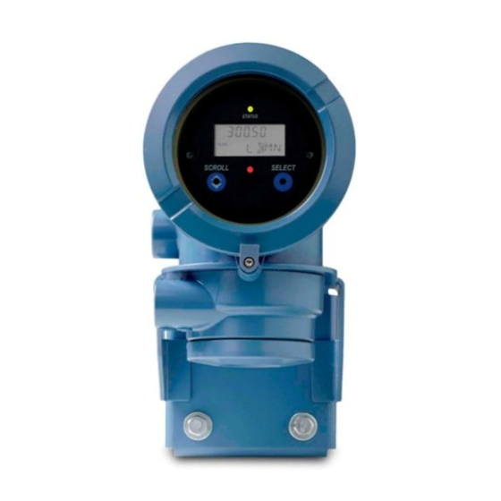
- Page 1 Configuration and Use Manual MMI-20019033, Rev AC March 2022 ™ Micro Motion 1700 Transmitters with Intrinsically Safe Outputs Configuration and Use Manual...
- Page 2 Micro Motion employees. Micro Motion will not accept your returned equipment if you fail to follow Micro Motion procedures. Return procedures and forms are available on our web support site at www.emerson.com, or by phoning the Micro Motion Customer Service department.
-
Page 3: Table Of Contents
Configuration and Use Manual Contents MMI-20019033 March 2022 Contents Chapter 1 Before you begin......................7 1.1 About this manual........................7 1.2 Transmitter model code......................7 1.3 Communications tools and protocols..................7 1.4 Related documentation....................... 8 Chapter 2 Quick start......................... 9 2.1 Power up the transmitter...................... - Page 4 10.7 Check for internal electrical problems..................139 10.8 Check Flow Direction ......................141 10.9 Flow measurement problems ....................142 10.10 Frequency Output problems....................144 10.11 Check Frequency Output Fault Action ................. 144 10.12 Check Frequency Output Scaling Method ................145 Micro Motion 1700 Transmitters with Intrinsically Safe Outputs...
- Page 5 Configuration and Use Manual Contents MMI-20019033 March 2022 10.13 Check grounding......................... 145 10.14 Check the HART communication loop................. 145 10.15 Check HART Address and mA Output Action................146 10.16 Check HART burst mode...................... 146 10.17 Perform loop tests....................... 146 10.18 Check Lower Range Value and Upper Range Value ..............150 10.19 Milliamp output problems....................
- Page 6 Contents Configuration and Use Manual March 2022 MMI-20019033 Micro Motion 1700 Transmitters with Intrinsically Safe Outputs...
-
Page 7: Before You Begin
Before you begin MMI-20019033 March 2022 1 Before you begin 1.1 About this manual This manual helps you configure, commission, use, maintain, and troubleshoot Micro Motion 1700 transmitters with intrinsically safe outputs. Important This manual assumes that: • The transmitter has been installed correctly and completely according to the instructions in the transmitter installation manual •... -
Page 8: Related Documentation
Micro Motion Series 1000 and Series 2000 Transmitters with MVD Technology Product Data Sheet • Micro Motion 1700 and 2700 Installation Manual • Micro Motion Enhanced Density Application Manual • Modbus Interface Tool • Sensor installation manual Micro Motion 1700 Transmitters with Intrinsically Safe Outputs... -
Page 9: Chapter 2 Quick Start
Configuration and Use Manual Quick start MMI-20019033 March 2022 2 Quick start 2.1 Power up the transmitter The transmitter must be powered up for all configuration and commissioning tasks, or for process measurement. Procedure WARNING If the transmitter is in a hazardous area, do not remove the housing cover while the transmitter is powered up. -
Page 10: Transmitter Status Reported By Led
Identify the connection type to use, and follow the instructions for that connection type in the appropriate appendix. Communications tool Connection type to use Instructions ProLink III Service port Using ProLink III with the transmitter Field Communicator HART Using a field communicator with the transmitter Micro Motion 1700 Transmitters with Intrinsically Safe Outputs... -
Page 11: Verify Mass Flow Measurement
Configuration and Use Manual Quick start MMI-20019033 March 2022 2.4 Verify mass flow measurement Check to see that the mass flow rate reported by the transmitter is accurate. You can use any available method. Procedure • Read the value for Mass Flow Rate on the transmitter display. Menu →... -
Page 12: Terminology Used With Zero Verification And Zero Calibration
Zero Stability value. Zero Calibration The procedure used to determine the zero value. Zero Time The time period over which the Zero Calibration procedure is performed. Unit = seconds. Micro Motion 1700 Transmitters with Intrinsically Safe Outputs... - Page 13 Configuration and Use Manual Quick start MMI-20019033 March 2022 Term Definition Field Verification Zero A 3-minute running average of the Live Zero value, calculated by the transmitter. Unit = configured mass flow measurement unit. Zero Verification A procedure used to evaluate the stored zero and determine whether or not a field zero can improve measurement accuracy.
- Page 14 Quick start Configuration and Use Manual March 2022 MMI-20019033 Micro Motion 1700 Transmitters with Intrinsically Safe Outputs...
-
Page 15: Introduction To Configuration And Commissioning
Configuration and Use Manual Introduction to configuration and commissioning MMI-20019033 March 2022 3 Introduction to configuration and commissioning 3.1 Configuration flowchart Use the following flowchart as a general guide to the configuration and commissioning process. Some options may not apply to your installation. Detailed information is provided in the remainder of this manual. -
Page 16: Default Values And Ranges
You cannot restore factory configurations with a 700 core. Restoring the factory configuration is not a common action. You may want to contact customer support to see if there is a preferred method to resolve any issues. Micro Motion 1700 Transmitters with Intrinsically Safe Outputs... -
Page 17: Configure Process Measurement
Configuration and Use Manual Configure process measurement MMI-20019033 March 2022 4 Configure process measurement 4.1 Configure mass flow measurement The mass flow measurement parameters control how mass flow is measured and reported. 4.1.1 Configure Mass Flow Measurement Unit Display OFF-LINE MAINT → OFF-LINE CONFG → UNITS → MASS ProLink III Device Tools →... - Page 18 5. Set Mass Flow Label to the name you want to use for the mass flow unit. 6. Set Mass Total Label to the name you want to use for the mass total and mass inventory unit. Micro Motion 1700 Transmitters with Intrinsically Safe Outputs...
-
Page 19: Configure Flow Damping
Configuration and Use Manual Configure process measurement MMI-20019033 March 2022 The special measurement unit is stored in the transmitter. You can configure the transmitter to use the special measurement unit at any time. Example: Defining a special measurement unit for mass flow You want to measure mass flow in ounces per second (oz/sec). -
Page 20: Configure Mass Flow Cutoff
Mass Flow Cutoff affects all reported values and values used in other transmitter behavior (e.g., events defined on mass flow). mA Output Cutoff affects only mass flow values reported through mA Output. Micro Motion 1700 Transmitters with Intrinsically Safe Outputs... -
Page 21: Configure Volume Flow Measurement For Liquid Applications
Configuration and Use Manual Configure process measurement MMI-20019033 March 2022 Example: Cutoff interaction with mA Output Cutoff lower than Mass Flow Cutoff Configuration: • mA Output Process Variable: Mass Flow Rate • Frequency Output Process Variable: Mass Flow Rate mA Output Cutoff: 10 g/sec •... -
Page 22: Configure Volume Flow Measurement Unit For Liquid Applications
Cubic feet per minute CUF/MN ft3/min Cuft/min Cubic feet per hour CUFT/H ft3/hr Cuft/h Cubic feet per day CUFT/D ft3/day Cuft/d Cubic meters per second M3/S m3/sec Cum/s Cubic meters per minute M3/MIN m3/min Cum/min Micro Motion 1700 Transmitters with Intrinsically Safe Outputs... - Page 23 Configuration and Use Manual Configure process measurement MMI-20019033 March 2022 Label Unit description Display ProLink III Field Communicator Cubic meters per hour M3/H m3/hr Cum/h Cubic meters per day M3/D m3/day Cum/d U.S. gallons per second USGPS US gal/sec gal/s U.S.
-
Page 24: Configure Volume Flow Cutoff
4.2.3 Configure Volume Flow Cutoff Display Not available Device Tools → Configuration → Process Measurement → Flow ProLink III Configure → Manual Setup → Measurements → Flow → Volume Flow Cutoff Field Communicator Micro Motion 1700 Transmitters with Intrinsically Safe Outputs... - Page 25 Configuration and Use Manual Configure process measurement MMI-20019033 March 2022 Volume Flow Cutoff specifies the lowest volume flow rate that will be reported as measured. All volume flow rates below this cutoff are reported as 0. Procedure Set Volume Flow Cutoff to the value you want to use. The default value for Volume Flow Cutoff is 0.0 l/sec (liters per second).
-
Page 26: Configure Gsv Flow Measurement
From the Source field, choose the method to supply gas base density data and perform the required setup. Option Description Fixed Value or Digital A host writes gas base density data to the meter at appropriate intervals. Communications Continue to Configure fixed value or digital communications. Micro Motion 1700 Transmitters with Intrinsically Safe Outputs... - Page 27 Configuration and Use Manual Configure process measurement MMI-20019033 March 2022 Option Description Poll for external value The meter polls an external HART device for gas base density data in order to then compute gas standard volume from the mass flow and gas base density.
-
Page 28: Configure Gas Standard Volume Flow Unit
Nm3/sec Normal cubic meters per minute NM3/MN Nm3/sec Nm3/min Normal cubic meters per hour NM3/H Nm3/hr Nm3/hr Normal cubic meters per day NM3/D Nm3/day Nm3/day Normal liters per second NLPS NLPS NLPS Micro Motion 1700 Transmitters with Intrinsically Safe Outputs... - Page 29 Configuration and Use Manual Configure process measurement MMI-20019033 March 2022 Label Unit description Display ProLink III Field Communicator Normal liters per minute NLPM NLPM NLPM Normal liters per hour NLPH NLPH NLPH Normal liters per day NLPD NLPD NLPD Standard cubic feet per second SCFS SCFS SCFS...
-
Page 30: Configure Gas Standard Volume Flow Cutoff
The default value for Gas Standard Volume Flow Cutoff is 0.0. The lower limit is 0.0. There is no upper limit. The recommended value is 0.5% of the nominal flow rate of the attached sensor. See the sensor specifications. Micro Motion 1700 Transmitters with Intrinsically Safe Outputs... -
Page 31: Configure Flow Direction
Configuration and Use Manual Configure process measurement MMI-20019033 March 2022 Interaction between Gas Standard Volume Flow Cutoff and mA Output Cutoff Gas Standard Volume Flow Cutoff defines the lowest Gas Standard Volume flow value that the transmitter will report as measured. mA Output Cutoff defines the lowest flow rate that will be reported through mA Output. -
Page 32: Options For Flow Direction
The effect of Flow Direction on the mA Outputs depends on Lower Range Value configured for the mA Output: • If Lower Range Value is set to 0, see Figure 4-1. If Lower Range Value is set to a negative value, see • Figure 4-2. Micro Motion 1700 Transmitters with Intrinsically Safe Outputs... - Page 33 Configuration and Use Manual Configure process measurement MMI-20019033 March 2022 Figure 4-1: Effect of Flow Direction on the mA Output: Lower Range Value = 0 Flow Direction = Forward Flow Direction = Reverse, Negate Forward Flow Direction = Absolute Value, Bidirectional, Negate Bidirectional Reverse flow Forward flow...
- Page 34 Under conditions of reverse flow, if the absolute value of the flow rate equals or exceeds 100 g/sec, the mA Output will be proportional to the absolute value of the flow rate up to 20.5 mA, and will be level at 20.5 mA at higher absolute values. Micro Motion 1700 Transmitters with Intrinsically Safe Outputs...
- Page 35 Configuration and Use Manual Configure process measurement MMI-20019033 March 2022 Effect of flow direction on Frequency Outputs Flow direction affects how the transmitter reports flow values via the Frequency Outputs. The Frequency Outputs are affected by flow direction only if Frequency Output Process Variable is set to a flow variable. Table 4-1: Effect of the flow direction parameter and actual flow direction on Frequency Outputs Actual flow direction Flow Direction setting...
-
Page 36: Configure Density Measurement
Density Measurement Unit controls the measurement units that will be used in density calculations and reporting. Procedure Set Density Measurement Unit to the option you want to use. The default setting for Density Measurement Unit is g/cm3 (grams per cubic centimeter). Micro Motion 1700 Transmitters with Intrinsically Safe Outputs... -
Page 37: Configure Two-Phase Flow Parameters
Configuration and Use Manual Configure process measurement MMI-20019033 March 2022 Options for Density Measurement Unit The transmitter provides a standard set of measurement units for Density Measurement Unit. Different communications tools may use different labels. Label Unit description Display ProLink III Field Communicator Specific gravity Grams per cubic centimeter... -
Page 38: Configure Density Damping
If Two-Phase Flow Timeout is set to 0.0 seconds, the outputs that represent flow rate will report a flow rate of 0 as soon as two-phase flow is detected. 4.5.3 Configure Density Damping Display Not available Micro Motion 1700 Transmitters with Intrinsically Safe Outputs... - Page 39 Configuration and Use Manual Configure process measurement MMI-20019033 March 2022 ProLink III Device Tools → Configuration → Process Measurement → Density Field Communicator Configure → Manual Setup → Measurements → Density → Density Damping Density Damping controls the amount of damping that will be applied to the line density value. Damping is used to smooth out small, rapid fluctuations in process measurement.
-
Page 40: Configure Density Cutoff
Configure → Manual Setup → Measurements → Temperature → Temperature Unit Temperature Measurement Unit specifies the unit that will be used for temperature measurement. Procedure Set Temperature Measurement Unit to the option you want to use. The default setting is Degrees Celsius. Micro Motion 1700 Transmitters with Intrinsically Safe Outputs... -
Page 41: Configure Temperature Damping
Configuration and Use Manual Configure process measurement MMI-20019033 March 2022 Options for Temperature Measurement Unit The transmitter provides a standard set of units for Temperature Measurement Unit. Different communications tools may use different labels for the units. Label Unit description Display ProLink III Field Communicator... -
Page 42: Effect Of Temperature Damping On Process Measurement
Not all sensors or applications require pressure compensation. The pressure effect for a specific sensor model can be found in the product data sheet located at www.emerson.com. If you are uncertain about implementing pressure compensation, contact customer service. - Page 43 Configuration and Use Manual Configure process measurement MMI-20019033 March 2022 5. Enter Flow Factor for your sensor. The flow factor is the percent change in the flow rate per PSI. When entering the value, reverse the sign. Example If the flow factor is 0.000004 % per PSI, enter −0.000004 % per PSI . 6.
-
Page 44: Configure Pressure Compensation Using The Field Communicator
Polling for pressure a. Ensure that the primary mA Output has been wired to support HART polling. b. Choose Online → Configure → Manual Setup → Measurements → External Pressure/Temperature → External Polling. Micro Motion 1700 Transmitters with Intrinsically Safe Outputs... -
Page 45: Options For Pressure Measurement Unit
Configuration and Use Manual Configure process measurement MMI-20019033 March 2022 Option Setup c. Set Poll Control to Poll As Primary Host or Poll as Secondary Host. d. Choose an unused polling slot. e. Set External Tag to the HART tag of the external pressure device. f. - Page 46 Grams per square centimeter G/SCM g/cm2 g/Sqcm Kilograms per square centimeter KG/SCM kg/cm2 kg/Sqcm Pascals pascals Kilopascals Kilopascals Megapascals Megapascals Torr @ 0 °C TORR Torr @ 0 °C torr Atmospheres atms atms Micro Motion 1700 Transmitters with Intrinsically Safe Outputs...
-
Page 47: Configure Device Options And Preferences
Configuration and Use Manual Configure device options and preferences MMI-20019033 March 2022 5 Configure device options and preferences 5.1 Configure the transmitter display You can control the process variables shown on the display and a variety of display behaviors. 5.1.1 Configure the language used for the display Display OFF-LINE MAINT →... -
Page 48: Configure The Number Of Decimal Places (Precision) Shown On The Display
Output. If you change the configuration of mA Output Process Variable, Display Variable 1 will be updated automatically. 5.1.3 Configure the number of decimal places (precision) shown on the display Display Not available Micro Motion 1700 Transmitters with Intrinsically Safe Outputs... -
Page 49: Configure The Refresh Rate Of Data Shown On The Display
Configuration and Use Manual Configure device options and preferences MMI-20019033 March 2022 ProLink III Device Tools → Configuration → Transmitter Display → Display Variables Field Communicator Configure → Manual Setup → Display → Decimal Places You can specify the number of decimal places (precision) that are shown on the display for each process variable or diagnostic variable. -
Page 50: Enable Or Disable The Display Backlight
Blinking, the status LED does not blink, whether alerts are acknowledged or not. It still changes color to indicate active alerts. Procedure Enable or disable Status LED Blinking. The default setting is Enabled. Micro Motion 1700 Transmitters with Intrinsically Safe Outputs... -
Page 51: Enable Or Disable Operator Actions From The Display
Configuration and Use Manual Configure device options and preferences MMI-20019033 March 2022 5.2 Enable or disable operator actions from the display You can configure the transmitter to let the operator perform specific actions using the display. 5.2.1 Enable or disable Totalizer Start/Stop from the display Display OFF-LINE MAINT →... -
Page 52: Enable Or Disable The Acknowledge All Alerts Display Command
OFF-LINE MAINT → OFF-LINE CONFG → DISPLAY ProLink III Device Tools → Configuration → Transmitter Display → Display Security Field Communicator Configure → Manual Setup → Display → Offline Variable Menu Features Micro Motion 1700 Transmitters with Intrinsically Safe Outputs... - Page 53 Configuration and Use Manual Configure device options and preferences MMI-20019033 March 2022 You can control operator access to different sections of the display off-line menu. You can also configure a password to control access. Procedure 1. To control operator access to the maintenance section of the off-line menu, enable or disable Off-Line Menu.
-
Page 54: Configure Response Time Parameters
All available process variables are calculated at 100 Hz. Use this option only if required by your application. If you change Update Rate, the settings for Flow Damping, and Density Damping are automatically adjusted. Micro Motion 1700 Transmitters with Intrinsically Safe Outputs... -
Page 55: Configure Response Time
Configuration and Use Manual Configure device options and preferences MMI-20019033 March 2022 2. If you set Update Rate to Special, select the process variable to be polled at 100 Hz. Effects of Update Rate = Special Incompatible features and functions Special mode is not compatible with the following features and functions: •... -
Page 56: Configure Alert Handling
The default value is 0 seconds. The range is 0 to 60 seconds. If you set Fault Timeout to 0, fault actions are performed as soon as the alert condition is detected. Micro Motion 1700 Transmitters with Intrinsically Safe Outputs... -
Page 57: Configure Status Alert Severity
Configuration and Use Manual Configure device options and preferences MMI-20019033 March 2022 The fault timeout period begins when the transmitter detects an alert condition. During the fault timeout period, the transmitter continues to report its last valid measurements. If the fault timeout period expires while the alert is still active, the fault actions are performed. If the alert condition clears before the fault timeout expires, no fault actions are performed. - Page 58 A023 Internal Totals Corrupt Fault Applies only to flowmeters with the (Core Processor) standard core processor. A024 Program Corrupt (Core Fault Applies only to flowmeters with the Processor) standard core processor. Micro Motion 1700 Transmitters with Intrinsically Safe Outputs...
- Page 59 Configuration and Use Manual Configure device options and preferences MMI-20019033 March 2022 Table 5-2: Status alerts and Status Alert Severity (continued) Alert code Status message Default severity Notes Configurable? A025 Boot Sector Fault (Core Fault Applies only to flowmeters with the Processor) standard core processor.
-
Page 60: Configure Informational Parameters
The informational parameters can be used to identify or describe your meter. They are not used in process measurement and they are not required. 5.6.1 Configure Sensor Serial Number Display Not available Micro Motion 1700 Transmitters with Intrinsically Safe Outputs... -
Page 61: Configure Sensor Liner Material
Configuration and Use Manual Configure device options and preferences MMI-20019033 March 2022 ProLink III Device Tools → Configuration → Informational Parameters → Sensor Field Communicator Configure → Manual Setup → Info Parameters → Sensor Information → Sensor Serial Number Sensor Serial Number lets you store the serial number of the sensor component of your flowmeter in transmitter memory. -
Page 62: Configure Descriptor
Your message can be up to 32 characters long. 5.6.7 Configure Date Display Not available ProLink III Device Tools → Configuration → Informational Parameters → Transmitter Field Communicator Configure → Manual Setup → Info Parameters → Transmitter Info → Date Micro Motion 1700 Transmitters with Intrinsically Safe Outputs... - Page 63 Configuration and Use Manual Configure device options and preferences MMI-20019033 March 2022 Date lets you store a static date (not updated by the transmitter) in transmitter memory. This parameter is not used in processing and is not required. Procedure Enter the date you want to use, in the form mm/dd/yyyy . ProLink III provides a calendar tool to help you select the date.
- Page 64 Configure device options and preferences Configuration and Use Manual March 2022 MMI-20019033 Micro Motion 1700 Transmitters with Intrinsically Safe Outputs...
-
Page 65: Integrate The Meter With The Control System
Configuration and Use Manual Integrate the meter with the control system MMI-20019033 March 2022 6 Integrate the meter with the control system 6.1 Configure the transmitter channels OFF-LINE MAINT → OFF-LINE CONFG → IO → CH B Display Device Tools → Configuration → I/O → Outputs ProLink III Configure →... -
Page 66: Configure Ma Output Process Variable
Gas standard volume flow GSV F Gas Standard Volume Flow Gas vol flo rate Rate Mass flow rate MFLOW Mass Flow Rate Mass flo Volume flow rate VFLOW Volume Flow Rate Vol flo Micro Motion 1700 Transmitters with Intrinsically Safe Outputs... -
Page 67: Configure Lower Range Value (Lrv) And Upper Range Value (Urv)
Configuration and Use Manual Integrate the meter with the control system MMI-20019033 March 2022 Table 6-2: PVR mA Output process variables Process variable Label Display ProLink III Field Communicator Uncorrected oil flow Oil Flow Rate At Line Oil Flow Rate at Line Uncorrected water cut WATER% Water Cut At Line... -
Page 68: Configure Ao Cutoff
Set AO Cutoff as desired. The default value for AO Cutoff is 0.0 g/sec. For most applications, the default value of AO Cutoff should be used. Contact customer service before changing AO Cutoff. Micro Motion 1700 Transmitters with Intrinsically Safe Outputs... -
Page 69: Configure Added Damping
Configuration and Use Manual Integrate the meter with the control system MMI-20019033 March 2022 Interaction between AO Cutoff and process variable cutoffs When mA Output Process Variable is set to a flow variable (for example, mass flow rate or volume flow rate), AO Cutoff interacts with Mass Flow Cutoff or Volume Flow Cutoff. -
Page 70: Configure Ma Output Fault Action And Ma Output Fault Level
6.2.5 Configure mA Output Fault Action and mA Output Fault Level Display Not available ProLink III Device Tools → Configuration → Fault Processing Field Communicator Configure → Manual Setup → Inputs/Outputs → mA Output → MA0 Fault Settings Micro Motion 1700 Transmitters with Intrinsically Safe Outputs... -
Page 71: Configure The Frequency Output
Configuration and Use Manual Integrate the meter with the control system MMI-20019033 March 2022 mA Output Fault Action controls the behavior of the mA Output if the transmitter encounters an internal fault condition. Note For some faults only: If Fault Timeout is set to a non-zero value, the transmitter will not implement the fault action until the timeout has elapsed. -
Page 72: Configure Frequency Output Polarity
Frequency Output Scaling Method as required by your frequency receiving device. Procedure 1. Set Frequency Output Scaling Method. Option Description Frequency=Flow (default) Frequency calculated from flow rate Pulses/Unit A user-specified number of pulses represents one flow unit Micro Motion 1700 Transmitters with Intrinsically Safe Outputs... -
Page 73: Configure Frequency Output Fault Action And Frequency Output Fault Level
Configuration and Use Manual Integrate the meter with the control system MMI-20019033 March 2022 Option Description Units/Pulse A pulse represents a user-specified number of flow units 2. Set additional required parameters. If you set Frequency Output Scaling Method to Frequency=Flow, set Rate Factor and Frequency •... - Page 74 If Digital Communications Fault Action is set to NAN (not a number), you cannot set mA Output Fault Action or Frequency Output Fault Action to None. If you try to do this, the transmitter will not accept the configuration. Micro Motion 1700 Transmitters with Intrinsically Safe Outputs...
-
Page 75: Configure The Discrete Output
Configuration and Use Manual Integrate the meter with the control system MMI-20019033 March 2022 6.4 Configure the Discrete Output The Discrete Output is used to report specific meter or process conditions. The Discrete Output parameters control which condition is reported and how it is reported. Restriction Before you can configure the Discrete Output, you must configure a channel to operate as a Discrete Output. - Page 76 4. Set Hysteresis to the percentage of variation above and below the setpoint that will operate as a deadband. Hysteresis defines a range around the setpoint within which the flow switch will not change. The default is 5%. The valid range is 0.1% to 10%. Micro Motion 1700 Transmitters with Intrinsically Safe Outputs...
-
Page 77: Configure Discrete Output Polarity
Configuration and Use Manual Integrate the meter with the control system MMI-20019033 March 2022 Example If Flow Switch Setpoint = 100 g/sec and Hysteresis = 5% , and the first measured flow rate is above 100 g/sec, the Discrete Output is OFF. It will remain OFF unless the flow rate drops below 95 g/sec. If this happens, the Discrete Output will turn ON, and remain ON until the flow rate rises above 105 g/sec. -
Page 78: Configure Events
A basic event is used to provide notification of process changes. A basic event occurs (is ON) if the real-time value of a user-specified process variable moves above (HI) or below (LO) a user-defined setpoint. You can Micro Motion 1700 Transmitters with Intrinsically Safe Outputs... -
Page 79: Configure An Enhanced Event
Configuration and Use Manual Integrate the meter with the control system MMI-20019033 March 2022 define up to two basic events. Event status can be queried via digital communications, and a Discrete Output can be configured to report event status. Procedure 1. - Page 80 Before assigning actions to an enhanced event, check the status of the event. If it is ON, all assigned actions will be performed when the new configuration is implemented. If this is not acceptable, wait until an appropriate time to assign actions to the event. Micro Motion 1700 Transmitters with Intrinsically Safe Outputs...
-
Page 81: Configure Digital Communications
Configuration and Use Manual Integrate the meter with the control system MMI-20019033 March 2022 6.6 Configure digital communications The digital communications parameters control how the transmitter will communicate using digital communications. Your transmitter supports the following types of digital communications: •... - Page 82 3. Ensure that the burst output variables are set appropriately. • If you set Burst Mode Output to send four user-specified variables, set the four process variables to be sent in each burst. Micro Motion 1700 Transmitters with Intrinsically Safe Outputs...
- Page 83 Configuration and Use Manual Integrate the meter with the control system MMI-20019033 March 2022 • If you set Burst Mode Output to any other option, ensure that the HART variables are set as desired. Configure HART variables (PV, SV, TV, QV) Display Not available Device Tools →...
- Page 84 Variable (QV ) ✓ Unremediated Density Table 6-10: PVR, TBR, and TMR HART process variables Process variable Primary Secondary Third Variable Fourth Variable (PV) Variable (SV) (TV) Variable (QV ) ✓ Total Remediated Time Micro Motion 1700 Transmitters with Intrinsically Safe Outputs...
-
Page 85: Configure Digital Communications Fault Action
Configuration and Use Manual Integrate the meter with the control system MMI-20019033 March 2022 Interaction of HART variables and transmitter outputs The HART variables are automatically reported through specific transmitter outputs. They may also be reported through HART burst mode, if enabled on your transmitter. Table 6-11: HART variables and transmitter outputs HART variable Reported via... - Page 86 If Digital Communications Fault Action is set to NAN (not a number), you cannot set mA Output Fault Action or Frequency Output Fault Action to None. If you try to do this, the transmitter will not accept the configuration. Micro Motion 1700 Transmitters with Intrinsically Safe Outputs...
-
Page 87: Complete The Configuration
Configuration and Use Manual Complete the configuration MMI-20019033 March 2022 7 Complete the configuration 7.1 Test or tune the system using sensor simulation Use sensor simulation to test the system's response to a variety of process conditions, including boundary conditions, problem conditions, or alert conditions, or to tune the loop. Prerequisites Before enabling sensor simulation, ensure that your process can tolerate the effects of the simulated process values. -
Page 88: Sensor Simulation
Sensor simulation does not affect any diagnostic values. Unlike actual mass flow rate and density values, the simulated values are not temperature-compensated (adjusted for the effect of temperature on the sensor’s flow tubes). Micro Motion 1700 Transmitters with Intrinsically Safe Outputs... -
Page 89: Back Up Transmitter Configuration
Configuration and Use Manual Complete the configuration MMI-20019033 March 2022 7.2 Back up transmitter configuration ProLink III provides a configuration upload/download function which allows you to save configuration sets to your PC. This allows you to back up and restore your transmitter configuration. This is also a convenient way to replicate a configuration across multiple devices. - Page 90 Complete the configuration Configuration and Use Manual March 2022 MMI-20019033 Micro Motion 1700 Transmitters with Intrinsically Safe Outputs...
-
Page 91: Chapter 8 Transmitter Operation
Configuration and Use Manual Transmitter operation MMI-20019033 March 2022 8 Transmitter operation 8.1 Record the process variables Micro Motion suggests that you make a record of specific process variable measurements, including the acceptable range of measurements, under normal operating conditions. This data will help you recognize when the process or diagnostic variables are unusually high or low, and may help you diagnose and troubleshoot application issues. - Page 92 ProLink III allows you to choose the process variables that appear on the main screen. You can also choose whether to view data in Analog Gauge view or digital view, and you can customize the gauge settings. For more information, see the Prolink III user manual. Micro Motion 1700 Transmitters with Intrinsically Safe Outputs...
-
Page 93: View Process Variables Using The Field Communicator
Configuration and Use Manual Transmitter operation MMI-20019033 March 2022 8.2.3 View process variables using the Field Communicator Monitor process variables to maintain process quality. Procedure • To view current values of basic process variables, choose Overview. To view a more complete set of process variables, plus the current state of the outputs, choose Service •... -
Page 94: View And Acknowledge Status Alerts
Note Only Fault and Informational alerts are listed. The transmitter automatically filters out alerts with Status Alert Severity set to Ignore. Procedure Figure 8-2. Micro Motion 1700 Transmitters with Intrinsically Safe Outputs... - Page 95 Configuration and Use Manual Transmitter operation MMI-20019033 March 2022 Figure 8-2: Using the display to view and acknowledge the status alerts (alarms) Scroll and Select simultaneously for 4 seconds SEE ALERT Select Is ACK ALL enabled? ACK ALL Select Scroll EXIT Select Scroll...
- Page 96 If the alert is inactive when it is acknowledged, it will be removed from the list. — If the alert is active when it is acknowledged, it will be removed from the list when the alert condition clears. Micro Motion 1700 Transmitters with Intrinsically Safe Outputs...
-
Page 97: View Alerts Using The Field Communicator
Configuration and Use Manual Transmitter operation MMI-20019033 March 2022 Related information Alert data in transmitter memory 8.4.3 View alerts using the Field Communicator You can view a list containing all alerts that are active, or inactive but unacknowledged. Procedure To view active or unacknowledged alerts, choose Service Tools → Alerts. •... -
Page 98: Read Totalizer And Inventory Values
Scroll until the word TOTAL appears in the lower left corner of the display. Important Because all totalizers are started or stopped together, it does not matter which total you use. Micro Motion 1700 Transmitters with Intrinsically Safe Outputs... -
Page 99: Reset Totalizers
Configuration and Use Manual Transmitter operation MMI-20019033 March 2022 b) Select. c) Scroll until START appears beneath the current totalizer value. displays beneath the current totalizer value. Exit d) Select. e) Select again to confirm. f) Scroll to EXIT. • To stop all totalizers and inventories using the display: a) Scroll until the word TOTAL appears in the lower left corner of the display. - Page 100 Scroll until Reset displays beneath the current totalizer value. d) Select. and Yes? alternately flash beneath the current totalizer value. Reset e) Select again to confirm. f) Scroll to EXIT. g) Select. Micro Motion 1700 Transmitters with Intrinsically Safe Outputs...
-
Page 101: Reset Inventories
Configuration and Use Manual Transmitter operation MMI-20019033 March 2022 8.8 Reset inventories ProLink III Device Tools → Totalizer Control → Totalizer and Inventories → Reset Mass Inventory Device Tools → Totalizer Control → Totalizer and Inventories → Reset Volume Inventory Device Tools →... - Page 102 Transmitter operation Configuration and Use Manual March 2022 MMI-20019033 Micro Motion 1700 Transmitters with Intrinsically Safe Outputs...
-
Page 103: Chapter 9 Measurement Support
Configuration and Use Manual Measurement support MMI-20019033 March 2022 9 Measurement support 9.1 Options for measurement support Micro Motion provides several measurement support procedures to help you evaluate and maintain your flowmeter's accuracy. The following methods are available: • Smart Meter Verification (SMV) evaluates the structural integrity of the sensor tubes by comparing current tube stiffness to the stiffness measured at the factory. -
Page 104: Smv Test Preparation
9.2.3 Smart Meter Verification capabilities Basic Professional Capability Included Licensed • • Calibration coefficients audit • • Zero audit • • Electronics verification • • Automatic test scheduler • • History of previous 20 results Micro Motion 1700 Transmitters with Intrinsically Safe Outputs... - Page 105 Configuration and Use Manual Measurement support MMI-20019033 March 2022 Basic Professional Capability Included Licensed • Verification report Create and export with Prolink III, web page, or AMS SNAP-ON. 9.2.4 Run SMV Run an SMV test using the display Procedure 1. Navigate to the Smart Meter Verification menu. Figure 9-1: SMV –...
- Page 106 To Runcount (see Results Read) Scroll Correct condition To Enter Meter Verfy Select Run an SMV test using ProLink III Procedure 1. Choose Device Tools → Diagnostics → Meter Verification → Run Test. Micro Motion 1700 Transmitters with Intrinsically Safe Outputs...
- Page 107 Configuration and Use Manual Measurement support MMI-20019033 March 2022 You may need to wait a few seconds while ProLink III synchronizes its database with the transmitter data. 2. Enter any desired information on the Test Definition screen, and click Next. All information on this screen is optional.
-
Page 108: View Test Data
Scroll and Select simultaneously for 4 seconds Scroll ENTER METER VERFY Select RUN VERFY Scroll RESULTS READ Scroll SCHEDULE VERFY Scroll EXIT Select Select Select Scroll Select b) Scroll to Results Read and press Select. Micro Motion 1700 Transmitters with Intrinsically Safe Outputs... - Page 109 Configuration and Use Manual Measurement support MMI-20019033 March 2022 The runcount of the most recent test is displayed. c) To view data for this test, press Select, then press Scroll to scroll through test data. d) To select a different test, press Scroll, then press Select when the transmitter displays Results More?.
- Page 110 Abort Code 1: User-Initiated Abort . In this case, you can restart Smart Meter Verification without any further action. In the rare case any other abort occurs, contact factory support. Micro Motion 1700 Transmitters with Intrinsically Safe Outputs...
-
Page 111: Schedule Automatic Execution Of The Smv Test
Configuration and Use Manual Measurement support MMI-20019033 March 2022 In all cases where a Smart Meter Verification Professional test aborts, no report will be generated. Fail If a Smart Meter Verification Basic or Professional test ran at normal operating conditions while conditions were stable and failed, see Resolve a failed Smart Meter Verification test to determine the... - Page 112 To disable execution of a single scheduled test, set Set Next to 0. • To disable recurring execution, set Set Recur to 0. • To disable all scheduled execution, choose Turn Off Sched when you enter the Smart Meter Verification menu. Micro Motion 1700 Transmitters with Intrinsically Safe Outputs...
- Page 113 Configuration and Use Manual Measurement support MMI-20019033 March 2022 SMV flowchart: Scheduling test execution using the display Figure 9-6: Scheduling SMV test execution using the display SCHEDULE VERFY Select Schedule set? SCHED IS OFF TURN OFF SCHED/YES? Scroll Scroll Select Schedule deleted HOURS LEFT Scroll...
-
Page 114: Use Production Volume Reconciliation, Transient Mist Remediation, And Transient Bubble
HART with HART 7 enabled in order to view process variables over HART (default) Restriction PVR, TBR, and TMR process variables are available only over HART with HART 7 enabled (default). PVR, TBR, and TMR parameters cannot be configured with HART. Micro Motion 1700 Transmitters with Intrinsically Safe Outputs... -
Page 115: Pvr, Tbr, And Tmr Applications
PWL does not apply when measuring liquid flow. When better accuracy is required over the published gas measurement specifications, an Emerson-approved independent gas laboratory can calibrate gas up to 10 PWL adjustment points. -
Page 116: Zero The Meter
If the zero continues to fail, contact customer service. 9.6 Validate the meter Display OFF-LINE MAINT → Config MTR F ProLink III Device Tools → Configuration → Process Measurement → Flow Device Tools → Configuration → Process Measurement → Density Micro Motion 1700 Transmitters with Intrinsically Safe Outputs... - Page 117 Configuration and Use Manual Measurement support MMI-20019033 March 2022 Field Communicator Configure → Manual Setup → Measurements → Flow Configure → Manual Setup → Measurements → Density Meter validation compares flowmeter measurements reported by the transmitter to an external measurement standard. If the transmitter value for mass flow, volume flow, or density measurement is significantly different from the external measurement standard, you may want to adjust the corresponding meter factor.
-
Page 118: Alternate Method For Calculating The Meter Factor For Volume Flow
3. Ensure that the calculated meter factor does not fall outside 0.98 and 1.02. If the meter factor is outside these limits, contact customer service. 4. Configure the meter factor for volume flow in the transmitter. Micro Motion 1700 Transmitters with Intrinsically Safe Outputs... -
Page 119: Perform A (Standard) D1 And D2 Density Calibration
Configure → Manual Setup → Measurements → Optional Setup → LD Optimization. LD Optimization is used only with large sensors in hydrocarbon applications. If you are not using a field communicator, contact Emerson before continuing. • The calibrations must be performed without interruption, in the order shown. Make sure that you are prepared to complete the process without interruption. - Page 120 9.7.2 Perform a D1 and D2 density calibration using a field communicator Procedure 1. Read the Prerequisites in Perform a (standard) D1 and D2 density calibration if you have not already done so. Micro Motion 1700 Transmitters with Intrinsically Safe Outputs...
-
Page 121: Perform A D3 And D4 Density Calibration (T-Series Sensors Only)
Configuration and Use Manual Measurement support MMI-20019033 March 2022 2. See the following figure. Postrequisites If you disabled LD Optimization before the calibration procedure, re-enable it. 9.8 Perform a D3 and D4 density calibration (T-Series sensors only) For T-Series sensors, the optional D3 and D4 calibration could improve the accuracy of the density measurement if the density of your process fluid is less than 0.8 g/cm or greater than 1.2 g/cm If you perform the D3 and D4 calibration, note the following:... - Page 122 PC. If the calibration fails, restore the known values. 9.8.1 Perform a D3 or D3 and D4 density calibration using ProLink III Procedure Figure 9-7. Micro Motion 1700 Transmitters with Intrinsically Safe Outputs...
- Page 123 Configuration and Use Manual Measurement support MMI-20019033 March 2022 Figure 9-7: D3 or D3 and D4 density calibration using ProLink III Close shutoff valve downstream from sensor D3 Calibration D4 Calibration Fill sensor with D3 fluid Fill sensor with D4 fluid Device Tools >...
-
Page 124: Perform Temperature Calibration
Prerequisites The temperature calibration is a two-part procedure: temperature offset calibration and temperature slope calibration. The two parts must be performed without interruption, in the order shown. Ensure that you are Micro Motion 1700 Transmitters with Intrinsically Safe Outputs... -
Page 125: Perform Temperature Calibration Using The Display
Configuration and Use Manual Measurement support MMI-20019033 March 2022 prepared to complete the process without interruption. You will need a low-temperature calibration fluid and a high-temperature calibration fluid. You will not see the effect of the calibration until both the temperature offset calibration and the temperature slope calibration are complete. - Page 126 Calibration > Calibration > Temperature Calibration > Temperature Calibration > Temperature Calibration - Offset Temperature Calibration - Slope Enter temperature of Enter temperature of low-temperature fluid high-temperature fluid Start Calibration Start Calibration Done Micro Motion 1700 Transmitters with Intrinsically Safe Outputs...
-
Page 127: Perform Temperature Calibration Using The Field Communicator
Configuration and Use Manual Measurement support MMI-20019033 March 2022 9.9.3 Perform temperature calibration using the Field Communicator Procedure Temperature Offset calibration Temperature Slope calibration Fill sensor with low- Fill sensor with high- temperature fluid temperature fluid Wait until sensor achieves Wait until sensor achieves thermal equilibrium thermal equilibrium... - Page 128 Measurement support Configuration and Use Manual March 2022 MMI-20019033 Micro Motion 1700 Transmitters with Intrinsically Safe Outputs...
-
Page 129: Chapter 10 Troubleshooting
Configuration and Use Manual Troubleshooting MMI-20019033 March 2022 10 Troubleshooting 10.1 Status LED states The status LED on the transmitter indicates whether or not alerts are active. If alerts are active, view the alert list to identify the alerts, then take appropriate action to correct the alert condition. Your transmitter has a status LED only if it has a display. -
Page 130: Check The Core Processor Led
D. Base E. Core processor b) Rotate the transmitter counter-clockwise so that the cap screws are in the unlocked position. c) Gently lift the transmitter straight up, disengaging it from the cap screws. Micro Motion 1700 Transmitters with Intrinsically Safe Outputs... - Page 131 Configuration and Use Manual Troubleshooting MMI-20019033 March 2022 Important Do not disconnect or damage the wires that connect the transmitter to the core processor. d) Check the state of the core processor LED. 4. If you have a 9-wire remote installation: a) Remove the end-cap.
-
Page 132: Core Processor Led States
Check wiring between transmitter and sensor. pause Improper configuration Check sensor characterization parameters. Broken pin between sensor and The meter requires factory service. core processor 4 flashes per second Fault condition Check alert status. Micro Motion 1700 Transmitters with Intrinsically Safe Outputs... - Page 133 Configuration and Use Manual Troubleshooting MMI-20019033 March 2022 Table 10-1: Standard core processor LED states (continued) LED state Description Recommended actions Core processor receiving less • Verify power supply wiring to core processor. than 5 volts • If transmitter status LED is lit, transmitter is receiving power.
-
Page 134: Perform A 700 Core Processor Resistance Test
Rotate the transmitter counter-clockwise so that the cap screws are in the unlocked position. c) Gently lift the transmitter straight up, disengaging it from the cap screws. 4. If you have a 9-wire remote installation: a) Remove the end-cap. Micro Motion 1700 Transmitters with Intrinsically Safe Outputs... - Page 135 Configuration and Use Manual Troubleshooting MMI-20019033 March 2022 Figure 10-3: 9-wire remote installation components A. Transmitter B. Core processor C. 4 x cap screws (4 mm) D. End-cap b) Inside the core processor housing, loosen the three screws that hold the core processor mounting plate in place.
- Page 136 4. Tighten the screws, torquing to 6 to 8 in-lbs (0.7 to 0.9 N-m). 5. Replace the end-cap. 6. Restore power to the transmitter. Important When reassembling the meter components, be sure to grease all O-rings. Micro Motion 1700 Transmitters with Intrinsically Safe Outputs...
-
Page 137: Density Measurement Problems
Configuration and Use Manual Troubleshooting MMI-20019033 March 2022 10.5 Density measurement problems Problem Possible causes Recommended actions Inaccurate density • Problem with process fluid • Check your process conditions against the reading values reported by the device. • Incorrect density calibration factors •... -
Page 138: Check The Drive Gain
Correct process conditions so that the sensor tubes are full. completely full Two-phase flow Check for two-phase flow. See Check for two-phase flow (slug flow). Vibrating element not free Ensure that the vibrating element is free to vibrate. to vibrate Micro Motion 1700 Transmitters with Intrinsically Safe Outputs... -
Page 139: Collect Drive Gain Data
Configuration and Use Manual Troubleshooting MMI-20019033 March 2022 Erratic drive gain Table 10-4: Possible causes and recommended actions for erratic drive gain Possible cause Recommended actions Two-phase flow Check for two-phase flow. See Check for two-phase flow (slug flow). Polarity of pick-off reversed or polarity Applicable for a 9-wire sensor. -
Page 140: Check The Sensor Coils
5. Test the terminals in the sensor junction box for shorts to case. Test results will be inconclusive with nonconductive process fluids such as hydrocarbons. a) Leave the terminal blocks disconnected. Micro Motion 1700 Transmitters with Intrinsically Safe Outputs... -
Page 141: Check Flow Direction
Configuration and Use Manual Troubleshooting MMI-20019033 March 2022 b) Remove the lid of the junction box. c) Testing one terminal at a time, place a DMM lead on the terminal and the other lead on the sensor case. With the DMM set to its highest range, there should be infinite resistance on each lead. If there is any resistance at all, there is a short to case. -
Page 142: Flow Measurement Problems
Check for sources of vibration. • Verify damping configuration. • Verify that the measurement units are configured correctly for your application. • Check for two-phase flow. • Check for radio frequency interference. • Contact customer support. Micro Motion 1700 Transmitters with Intrinsically Safe Outputs... - Page 143 Configuration and Use Manual Troubleshooting MMI-20019033 March 2022 Problem Possible causes Recommended actions Erratic non-zero flow • Two-phase flow • Verify that the sensor orientation is rate when flow is appropriate for your application (refer to • Damping value too low steady the sensor installation manual).
-
Page 144: Frequency Output Problems
For the relevant status alerts, change the setting of Alert Severity to Ignore. • Restriction For some status alerts, Alert Severity is not configurable. 3. If there are no active fault conditions, continue troubleshooting. Micro Motion 1700 Transmitters with Intrinsically Safe Outputs... -
Page 145: Check Frequency Output Scaling Method
Configuration and Use Manual Troubleshooting MMI-20019033 March 2022 10.12 Check Frequency Output Scaling Method If Frequency Output Scaling Method is set incorrectly, the Frequency Output may report an incorrect value. Procedure 1. Verify the configuration of the Frequency Output. 2. If you changed the setting of Frequency Output Scaling Method, check the settings of all other Frequency Output parameters. -
Page 146: Check Hart Address And Ma Output Action
Before performing a loop test, configure the channels for the transmitter inputs and outputs that will be used in your application. Follow appropriate procedures to ensure that loop testing will not interfere with existing measurement and control loops. Micro Motion 1700 Transmitters with Intrinsically Safe Outputs... - Page 147 Configuration and Use Manual Troubleshooting MMI-20019033 March 2022 Procedure 1. Test the mA Output(s). a) Choose OFFLINE MAINT → SIM → AO1 SIM and select a low value, e.g., 4 mA. Dots traverse the display while the output is fixed. b) Read the mA current at the receiving device and compare it to the transmitter output.
- Page 148 The readings do not need to match exactly. If the values are slightly different, you can correct the discrepancy by trimming the output. h) Select UnFix mA. 2. Test the Frequency Output(s). Micro Motion 1700 Transmitters with Intrinsically Safe Outputs...
-
Page 149: Perform Loop Tests Using The Field Communicator
Configuration and Use Manual Troubleshooting MMI-20019033 March 2022 Note If the Weights & Measures application with NTEP approval is enabled on the transmitter, it is not possible to perform a loop test of the Frequency Output, even when the transmitter is unsecured. a) Choose Device Tools →... -
Page 150: Check Lower Range Value And Upper Range Value
If the process variable assigned to the mA Output falls below the configured Lower Range Value (LRV) or rises above the configured Upper Range Value (URV), the meter will post a saturation alert (A100), then perform Micro Motion 1700 Transmitters with Intrinsically Safe Outputs... -
Page 151: Milliamp Output Problems
Configuration and Use Manual Troubleshooting MMI-20019033 March 2022 the configured fault action. If the process variable assigned to the mA Output falls below the configured Lower Range Value (LRV) or rises above the configured Upper Range Value (URV), the meter will post an Output Saturated alert for the affected output, then perform the configured fault action. -
Page 152: Check Ma Output Fault Action
If the mA Output is reporting a constant value below 4 mA or above 20 mA, the transmitter may be in a fault condition. Procedure 1. Check the status alerts for active fault conditions. Micro Motion 1700 Transmitters with Intrinsically Safe Outputs... -
Page 153: Check The Trimming Of The Ma Output
Configuration and Use Manual Troubleshooting MMI-20019033 March 2022 2. If there are active fault conditions, the transmitter is performing correctly. If you want to change its behavior, consider the following options: • Change the setting of mA Output Fault Action. •... -
Page 154: Collect Pickoff Voltage Data
Before inspecting the power supply wiring, disconnect the power source. 3. Ensure that the terminals, wires, and wiring compartment are clean and dry. 4. Ensure that the power supply wires are connected to the correct terminals. Micro Motion 1700 Transmitters with Intrinsically Safe Outputs... -
Page 155: Check For Radio Frequency Interference (Rfi)
Configuration and Use Manual Troubleshooting MMI-20019033 March 2022 5. Ensure that the power supply wires are making good contact, and are not clamped to the wire insulation. 6. Inspect the voltage label inside the wiring compartment. The voltage supplied to the transmitter should match the voltage specified on the label. WARNING If the transmitter is in a hazardous area, do not reapply power to the transmitter with the housing cover removed. -
Page 156: Check Sensor-To-Transmitter Wiring
Micro Motion recommends leaving the Two-Phase Flow High Limit at the default value. 10.28 Status alerts, causes, and recommendations Not all of these alerts may apply to your type of transmitter. Micro Motion 1700 Transmitters with Intrinsically Safe Outputs... - Page 157 Configuration and Use Manual Troubleshooting MMI-20019033 March 2022 10.28.1 A001 Alert EEPROM Error (Core Processor) Cause The transmitter has detected a problem communicating with the sensor. Recommended actions 1. Cycle power to the meter. 2. Replace the core processor. 3. Contact customer support. 10.28.2 A002 Alert RAM Error (Core Processor)
- Page 158 The calibration factors are incorrect for the sensor type Recommended actions 1. Verify all of the characterization or calibration parameters. See the sensor tag or the calibration sheet for your meter. 2. Verify the setting of the Sensor Type parameter. Micro Motion 1700 Transmitters with Intrinsically Safe Outputs...
- Page 159 Configuration and Use Manual Troubleshooting MMI-20019033 March 2022 3. If Sensor Type = Curved Tube, ensure that no parameters specific to Straight Tube have been set. 4. Verify that internal wiring is secure and that there are no internal electrical problems. 5.
- Page 160 This alert is accompanied by A010, and will not clear until you cycle power to the meter. Recommended actions 1. Verify that there is no flow through the sensor. 2. Cycle power to the meter. 3. Retry the procedure. Micro Motion 1700 Transmitters with Intrinsically Safe Outputs...
- Page 161 Configuration and Use Manual Troubleshooting MMI-20019033 March 2022 10.28.11 A012 Alert Zero Calibration Failed: High Cause There are many possible causes, such as: • Too much flow, especially forward flow through the sensor during a calibration procedure • A zero result occurred that is too high. This alert is accompanied by A010, and will not clear until you cycle power to the meter.
- Page 162 3. Check the wiring between the sensor and the transmitter. 4. Verify that internal wiring is secure and that there are no internal electrical problems. 5. Contact customer support. 10.28.16 A018 Alert EEPROM Error (Transmitter) Micro Motion 1700 Transmitters with Intrinsically Safe Outputs...
- Page 163 Configuration and Use Manual Troubleshooting MMI-20019033 March 2022 Cause The transmitter has experienced a memory error. This alert will not clear until you cycle power to the meter. Recommended actions 1. Ensure that all wiring compartment covers are installed correctly. 2.
- Page 164 4. If Sensor Type=Curved Tube, ensure that no parameters specific to Straight Tube have been set. 10.28.20 A022 Alert Configuration Database Corrupt (Core Processor) Cause There has been an internal electronics failure. Micro Motion 1700 Transmitters with Intrinsically Safe Outputs...
- Page 165 Configuration and Use Manual Troubleshooting MMI-20019033 March 2022 Recommended actions 1. Cycle power to the meter. 2. Contact customer support. 10.28.21 A023 Alert Internal Totals Corrupt (Core Processor) Cause There has been an internal electronics failure. Recommended actions 1. Cycle power to the meter. 2.
- Page 166 Cause This can indicate a loss of communication between the transmitter and the display module. Recommended actions 1. Cycle power to the meter. 2. Replace the display module. 3. Contact customer support. Micro Motion 1700 Transmitters with Intrinsically Safe Outputs...
- Page 167 Configuration and Use Manual Troubleshooting MMI-20019033 March 2022 10.28.27 A030 Alert Incorrect Board Type Cause The loaded software is not compatible with the programmed board type. Recommended actions Contact customer support. 10.28.28 A031 Alert Low Power Cause The core processor or transmitter is not receiving enough power. This alert will not clear until you cycle power to the meter.
- Page 168 Actual conditions may be outside the normal conditions for which the output is configured. 3. Check for air in the flow tubes, tubes not filled, foreign material in the tubes, coating in the tubes, or other process problems. Micro Motion 1700 Transmitters with Intrinsically Safe Outputs...
- Page 169 Configuration and Use Manual Troubleshooting MMI-20019033 March 2022 4. Verify that the measurement units are configured correctly for your application. 5. Purge the sensor tubes. 10.28.33 A101 Alert mA Output 1 Fixed Cause The HART address is set to a non-zero value, or the mA Output is configured to send a constant value. Recommended actions 1.
- Page 170 The line density is outside the user-defined two-phase flow limits. Recommended actions 1. Check for two-phase flow. 2. Check the live density reading against the upper and lower two-phase flow limit settings. 10.28.38 A106 Alert Burst Mode Enabled Micro Motion 1700 Transmitters with Intrinsically Safe Outputs...
- Page 171 Configuration and Use Manual Troubleshooting MMI-20019033 March 2022 Cause HART burst mode is enabled. Recommended actions 1. No action required. 2. If desired, you can set Alert Severity Level to Ignore. 10.28.39 A107 Alert Power Reset Occurred Cause The transmitter has been restarted. Recommended actions No action is required.
- Page 172 3. Check whether the output has been set to a constant value vial digital communication. 10.28.44 A112 Alert Upgrade Transmitter Software Cause The transmitter software is down-level from the core processor software. Recommended actions Contact customer support. Micro Motion 1700 Transmitters with Intrinsically Safe Outputs...
- Page 173 Configuration and Use Manual Troubleshooting MMI-20019033 March 2022 10.28.45 A113 Alert mA Output 2 Saturated Cause The calculated mA Output value is outside the configured range. Recommended actions 1. Check the settings of Upper Range Value and Lower Range Value. 2.
- Page 174 A D[1 - 4] density calibration is in progress. Recommended actions No action required. 10.28.52 Reverse Flow Cause Flow through the device is in the reverse direction (against the flow arrow). Recommended actions No action is required. Micro Motion 1700 Transmitters with Intrinsically Safe Outputs...
-
Page 175: Temperature Measurement Problems
Configuration and Use Manual Troubleshooting MMI-20019033 March 2022 10.28.53 Zero Calibration in Progress Cause A zero calibration is in progress. Recommended actions No action required. 10.29 Temperature measurement problems Problem Possible causes Recommended actions Temperature reading • RTD failure • Check junction box for moisture or significantly different verdigris. - Page 176 Troubleshooting Configuration and Use Manual March 2022 MMI-20019033 Micro Motion 1700 Transmitters with Intrinsically Safe Outputs...
-
Page 177: Appendix A Using The Transmitter Display
Configuration and Use Manual Using the transmitter display MMI-20019033 March 2022 A Using the transmitter display This section explains how to use the 1700 display. Using the display, you can move through the menus, configure the application, monitor and control the application, and perform maintenance and diagnostic tasks. -
Page 178: Access And Use The Display Menu System
If you do not know the correct value for Off-Line Password, wait 30 seconds. The password screen will time out automatically and you will be returned to the previous screen. 3. Use the Scroll and Select optical switches to navigate to your destination in the display menu system. Micro Motion 1700 Transmitters with Intrinsically Safe Outputs... -
Page 179: Enter A Floating-Point Value Using The Display
Configuration and Use Manual Using the transmitter display MMI-20019033 March 2022 • Use Scroll to move through a list of options. • Use Select to choose the current option. 4. If Scroll flashes on the display, activate the Scroll optical switch, then the Select optical switch, and then the Scroll optical switch again. - Page 180 S = Sign. A minus sign (−) indicates a negative number. A blank indicates a positive number. • X.XXX = The 4-digit mantissa. • E = The exponent indicator. • YY = The 2-digit exponent. Micro Motion 1700 Transmitters with Intrinsically Safe Outputs...
- Page 181 Configuration and Use Manual Using the transmitter display MMI-20019033 March 2022 Procedure 1. Switch from decimal notation to exponential notation. a) Activate Select as required until the rightmost digit is flashing. b) Activate Scroll until E is displayed. c) Activate Select. If you have modified the value in decimal notation without saving the changes to transmitter memory, the changes will be lost when you switch to exponential notation.
-
Page 182: Display Codes For Process Variables
Refers to power input to the core processor RDENS Density at reference temperature Concentration measurement application only RPO_A Right pickoff amplitude Specific gravity units STD V Standard volume flow rate Concentration measurement application only Micro Motion 1700 Transmitters with Intrinsically Safe Outputs... -
Page 183: Codes And Abbreviations Used In Display Menus
Configuration and Use Manual Using the transmitter display MMI-20019033 March 2022 Table A-2: Display codes for process variables (continued) Code Definition Comment or reference STDVI Standard volume inventory Concentration measurement application only TCDENS Temperature-corrected density Petroleum measurement application only TCORI Temperature-corrected inventory Petroleum measurement application only TCORR... - Page 184 FAC Z Factory zero Flow calibration factor FLDIR Flow direction FL SW Flow switch FLSWT Frequency Output FO FREQ Frequency factor FO RATE Rate factor FREQ Frequency FR FL Frequency=Flow Gas standard volume Micro Motion 1700 Transmitters with Intrinsically Safe Outputs...
- Page 185 Configuration and Use Manual Using the transmitter display MMI-20019033 March 2022 Table A-3: Codes and abbreviations used in display menus (continued) Code or abbreviation Definition Comment or reference HYSTRSIS Hysteresis INTERN Internal Input/output LANG Language LOCK Write-protect LOOP CUR Loop current M_ASC Modbus ASCII M_RTU...
- Page 186 Water Flow Rate WATER% Uncorrected Water Cut PVR applications only WCT60% Water Cut 60F PVR applications only WRPRO Write protect PVR applications only WTR60 Corrected Net PVR applications only Water Flow XMTR Transmitter Micro Motion 1700 Transmitters with Intrinsically Safe Outputs...
-
Page 187: Appendix B Using Prolink Iii With The Transmitter
Micro Motion ProLink III with ProcessViz Software User Manual. In most ProLink III installations, the manual is installed with the ProLink III program. Additionally, the ProLink III manual is available on the documentation CD or at www.emerson.com. ProLink III features and functions ProLink III offers complete transmitter configuration and operation functions. -
Page 188: Connect With Prolink Iii
To connect to the transmitter in a hazardous environment, use a connection method that does not require removing the transmitter housing cover. Micro Motion 1700 Transmitters with Intrinsically Safe Outputs... - Page 189 Configuration and Use Manual Using ProLink III with the transmitter MMI-20019033 March 2022 Procedure 1. Attach the signal converter to the serial port or USB port on your PC. 2. Access the service port terminals: a) Remove the transmitter end-cap to access the wiring compartment. b) Loosen the screw on the Warning flap and open the power supply compartment.
-
Page 190: Make A Hart/Bell 202 Connection
Add resistance as necessary to achieve at least one volt across the connection points. Important HART/Bell 202 connections require a voltage drop of 1-5 VDC. To achieve this, add resistance of 250–600 Ω to the connection. Micro Motion 1700 Transmitters with Intrinsically Safe Outputs... - Page 191 Configuration and Use Manual Using ProLink III with the transmitter MMI-20019033 March 2022 Figure B-2: Connection to transmitter terminals – A. Computer B. Signal converter C. 250–600 Ω resistance D. Transmitter, with wiring compartment and power supply compartment opened E. External power supply Note This figure shows a serial port connection.
- Page 192 Add resistance as necessary to achieve at least one volt across the connection points. Important HART/Bell 202 connections require a voltage drop of 1-5 VDC. To achieve this, add resistance of 250–600 Ω to the connection. Micro Motion 1700 Transmitters with Intrinsically Safe Outputs...
- Page 193 Configuration and Use Manual Using ProLink III with the transmitter MMI-20019033 March 2022 Figure B-4: Connection over local loop – A. PC B. Signal converter C. Any combination of resistors R1, R2, and R3 as necessary to meet HART communication resistance requirements D.
- Page 194 Add resistance as necessary to achieve at least one volt across the connection points. Important HART/Bell 202 connections require a voltage drop of 1-5 VDC. To achieve this, add resistance of 250–600 Ω to the connection. Micro Motion 1700 Transmitters with Intrinsically Safe Outputs...
- Page 195 Configuration and Use Manual Using ProLink III with the transmitter MMI-20019033 March 2022 Figure B-6: Connection over multidrop network A. Signal converter B. 250–600 Ω resistance C. Devices on the network D. Master device 5. Start ProLink III. 6. Choose Connect to Physical Device. 7.
- Page 196 Increase or decrease resistance. • Ensure that there is no conflict with another HART master. If any other host (DCS or PLC) is connected to the mA Output, temporarily disconnect the DCS or PLC wiring. Micro Motion 1700 Transmitters with Intrinsically Safe Outputs...
-
Page 197: Appendix C Using A Field Communicator With The Transmitter
Configuration and Use Manual Using a field communicator with the transmitter MMI-20019033 March 2022 C Using a field communicator with the transmitter C.1 Basic information about field communicators A field communicator is a handheld configuration and management tool that can be used with a variety of devices, including Micro Motion transmitters. -
Page 198: Connect With A Field Communicator
D. Transmitter, with wiring compartment and power supply compartment opened 2. To connect to a point in the local HART loop, attach the leads from the field communicator to any point in the loop and add resistance as necessary. Micro Motion 1700 Transmitters with Intrinsically Safe Outputs... - Page 199 Configuration and Use Manual Using a field communicator with the transmitter MMI-20019033 March 2022 The field communicator must be connected across a resistance of 250–600 Ω. Figure C-2: Field communicator connection to local HART loop A. Field communicator B. 250–600 Ω resistance C.
- Page 200 Need help? The field communicator requires a minimum of 1 VDC across the connection leads to communicate. If necessary, increase the resistance at the connection point until 1 VDC is achieved. Micro Motion 1700 Transmitters with Intrinsically Safe Outputs...
-
Page 201: Appendix D Default Values And Ranges
Configuration and Use Manual Default values and ranges MMI-20019033 March 2022 D Default values and ranges D.1 Default values and ranges The default values and ranges represent the typical factory transmitter configuration. Depending on how the transmitter was ordered, certain values may have been configured at the factory and are not represented in the default values and ranges. - Page 202 Temperature calibration factor 1.00000T0.000 Pressure Pressure units Flow factor Density factor Cal pressure T-Series sensor D3 0 g/cm 0 g/cm 0 µsec 0 µsec DFQ1 DFQ2 Special units Base mass unit Base mass time Micro Motion 1700 Transmitters with Intrinsically Safe Outputs...
- Page 203 Configuration and Use Manual Default values and ranges MMI-20019033 March 2022 Table D-1: Transmitter default values and ranges (continued) Type Parameter Default Range Comments Mass flow conversion factor Base volume unit Base volume time Volume flow conversion factor Variable Primary variable Mass flow mapping Secondary variable...
- Page 204 Discrete Source Flow direction Output Fault Indicator None Power Internal Polarity Active high Display Backlight on/off Refresh rate 100 – 10,000 milliseconds milliseconds Variable 1 Mass flow rate Variable 2 Mass total Micro Motion 1700 Transmitters with Intrinsically Safe Outputs...
- Page 205 Configuration and Use Manual Default values and ranges MMI-20019033 March 2022 Table D-1: Transmitter default values and ranges (continued) Type Parameter Default Range Comments Variable 3 Volume flow rate Variable 4 Volume total Variable 5 Density Variable 6 Temperature Variable 7 Drive gain Variable 8–15 None...
- Page 206 Default values and ranges Configuration and Use Manual March 2022 MMI-20019033 Micro Motion 1700 Transmitters with Intrinsically Safe Outputs...
-
Page 207: Appendix E Transmitter Components And Installation Wiring
Configuration and Use Manual Transmitter components and installation wiring MMI-20019033 March 2022 E Transmitter components and installation wiring E.1 Installation types The transmitter was ordered and shipped to be installed in one of several possible configurations. Figure E-1: Integral installation The transmitter is mounted directly to the sensor. - Page 208 The 9-wire connection between the transmitter/core processor and the sensor must be field wired. The power supply must be field wired to the transmitter. A. Transmitter B. Field-wired 9-wire connection C. Junction box D. Sensor Micro Motion 1700 Transmitters with Intrinsically Safe Outputs...
-
Page 209: Power Supply Terminals And Ground
Configuration and Use Manual Transmitter components and installation wiring MMI-20019033 March 2022 Figure E-5: Remote core processor with remote sensor installation The transmitter, core processor, and sensor are all mounted separately. The 4-wire connection between the transmitter and core processor must be field wired. The 9-wire connection between the core processor and the sensor must be field wired. -
Page 210: Input/Output (I/O) Wiring Terminals
Transmitter components and installation wiring Configuration and Use Manual March 2022 MMI-20019033 E.3 Input/output (I/O) wiring terminals Figure E-7: I/O wiring terminals A. mA/HART B. Frequency Output or Discrete Output C. Unused Micro Motion 1700 Transmitters with Intrinsically Safe Outputs... -
Page 211: Appendix Fne 53 History
Configuration and Use Manual NE 53 history MMI-20019033 March 2022 F NE 53 history F.1 NE 53 history Important Not all features and capabilities described in this section may apply to your transmitter or configuration. August 2000, Version 1.x Modification type Change Expansion Added writing of the device tag using Modbus... - Page 212 Improvements to pressure and temperature polling • HART Tri-Loop and other communication improvements • Clarified the value returned by Modbus scaled integer registers during a fault condition Feature Discrete values now available through Modbus Micro Motion 1700 Transmitters with Intrinsically Safe Outputs...
- Page 213 Configuration and Use Manual NE 53 history MMI-20019033 March 2022 September 2006, version 5.x Modification type Change Expansion • Discrete Output assignable as a flow switch • Discrete Output fault indication configurability • Discrete Input support for multiple action assignments •...
- Page 214 Fast access to Live Zero in 100 Hz mode • Display used to disable user access to the Smart Meter Verification menu. Once disabled, access can only be enabled using ProLink III or a HART device Micro Motion 1700 Transmitters with Intrinsically Safe Outputs...
- Page 215 Configuration and Use Manual NE 53 history MMI-20019033 March 2022 Modification type Change Adjustment • Sensors that are not straight tube sensors are now correctly identified • The mA Output fixed alert is now set • The Factory Configuration Invalid status bit is now set correctly when connected to a 700 core processor —...
- Page 216 Added the ability to use the display to configure user access to the Smart Meter Verification menu on the display. This feature can be used only to disable access. Once disabled, access can only be enabled using ProLink III or a HART device. Micro Motion 1700 Transmitters with Intrinsically Safe Outputs...
- Page 217 Configuration and Use Manual MMI-20019033 March 2022 Configuration and Use Manual...
- Page 218 © 2022 Micro Motion, Inc. All rights reserved. The Emerson logo is a trademark and service mark of Emerson Electric Co. Micro Motion, ELITE, ProLink, MVD and MVD Direct Connect marks are marks of one of the Emerson Automation Solutions family of companies.
Need help?
Do you have a question about the Micro Motion 1700 and is the answer not in the manual?
Questions and answers