Sign In
Upload
Manuals
Brands
Emerson Manuals
Transmitter
MICRO MOTION 1500
Emerson MICRO MOTION 1500 Manuals
Manuals and User Guides for Emerson MICRO MOTION 1500. We have
8
Emerson MICRO MOTION 1500 manuals available for free PDF download: Configuration And Use Manual, Configuration And User Manual, User Manual, Installation Manual, Product Data Sheet
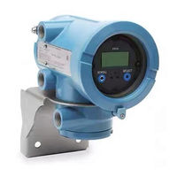
Emerson MICRO MOTION 1500 Configuration And Use Manual (282 pages)
Brand:
Emerson
| Category:
Transmitter
| Size: 8.46 MB
Table of Contents
Table of Contents
3
Chapter 1 Before You Begin
11
Overview
11
Safety
11
Determining Your Transmitter Type and Version
11
Transmitter Type, Installation Type, and Outputs Option Board
12
Version
13
Flowmeter Documentation
13
Using this Manual
13
Component Versions
14
Terminology
14
Communication Tools
15
Planning the Configuration
15
Pre-Configuration Worksheet
16
Micro Motion Customer Service
17
Chapter 2 Using the Transmitter Display
19
Overview
19
Components
19
Using the Optical Switches
20
Using the Display
20
Display Language
20
Viewing Process Variables
20
Display Menus
21
Display Password
21
Entering Floating-Point Values with the Display
22
Chapter 3 Connecting with Prolink II or Pocket Prolink Software
25
Overview
25
Requirements
25
Prolink II Configuration Upload/Download
26
Connecting from a PC to a Model 1700 or Model 2700 Transmitter
26
Connecting to the Service Port
27
Connecting to the RS-485 Terminals or an RS-485 Network
28
Connecting to the Primary Ma Output Terminals or to a HART Multidrop Network
30
Connecting from a PC to a Model 1500 or Model 2500 Transmitter
33
Connecting to the RS-485 Terminals or an RS-485 Network
33
Hart/Bell 202 Connections
36
Prolink II Language
37
Chapter 4 Connecting with the 275 HART Communicator or
39
Field Communicator
39
Overview
39
Communicator Models
39
Viewing the Device Descriptions
40
Using the 275 HART Communicator with the Model 2500
40
Connecting to a Transmitter
41
Connecting to Communication Terminals
41
Connecting to a Multidrop Network
43
Conventions Used in this Manual
43
HART Communicator Safety Messages and Notes
43
Chapter 5 Flowmeter Startup
45
Flowmeter Startup
45
Overview
45
Applying Power
46
Communication Methods after Power-Up
46
Performing a Loop Test
47
Trimming the Milliamp Outputs
48
Zeroing the Flowmeter
49
Preparing for Zero
49
Zero Procedure
50
Chapter 6 Required Transmitter Configuration
53
Overview
53
Characterizing the Flowmeter
54
When to Characterize
54
Characterization Parameters
54
How to Characterize
57
Configuring the Channels
57
Configuring the Measurement Units
57
Mass Flow Units
58
Volume Flow Units
59
Density Units
61
Temperature Units
61
Pressure Units
62
Configuring the Ma Output(S)
62
Configuring the Frequency Output(S)
62
Configuring the Discrete Output(S)
62
Configuring the Discrete Input
63
Establishing a Meter Verification Baseline
63
Chapter 7 Using the Transmitter
65
Overview
65
Special Applications
65
Recording Process Variables
66
Viewing Process Variables
66
With the Display
66
With Prolink II
66
With a Communicator
67
Viewing Transmitter Status and Alarms
67
Using the Status LED
67
Using the Display
67
Using Prolink II
69
Using the Communicator
69
Acknowledging Alarms
69
Using the Totalizers and Inventories
70
Viewing the Totalizers and Inventories
70
Controlling Totalizers and Inventories
71
Chapter 8 Optional Configuration
75
Overview
75
Configuration Map
75
How to Access a Parameter for Configuration
75
Configuring Standard Volume Flow Measurement for Gas
77
Using the Gas Wizard
77
Creating Special Measurement Units
78
About Special Measurement Units
78
Special Measurement Unit Procedure
79
Configuring the Petroleum Measurement Application (API Feature)
80
About the Petroleum Measurement Application
80
Configuring Cutoffs
82
Cutoffs and Volume Flow
83
Interaction with the AO Cutoffs
83
Configuring the Damping Values
83
Damping and Volume Measurement
84
Interaction with the Added Damping Parameter
84
Interaction with the Update Rate
84
Configuring the Update Rate
84
Effects of Special Mode
85
Configuring the Flow Direction Parameter
86
Configuring Events
89
Changing Event Setpoints from the Display
89
Configuring Slug Flow Limits and Duration
90
Configuring Fault Handling
91
Status Alarm Severity
91
Fault Timeout
95
Configuring the Display
95
Update Period
95
Language
95
Enabling and Disabling Display Functions
95
Changing the Scroll Rate
96
Changing the Display Password
96
Changing the Display Variables and Display Precision
96
Fixing Display Variable 1 to the Primary Ma Output
96
Configuring Digital Communications
97
Configuring Device Settings
97
Configuring Sensor Parameters
97
Configuring Write-Protect Mode
98
Chapter 9 Pressure Compensation, Temperature Compensation, and Polling
99
Overview
99
Pressure Compensation
99
Options
99
Pressure Correction Factors
100
Configuration
100
External Temperature Compensation
101
Configuring Polling
103
Chapter 10 Measurement Performance
107
Overview
107
Meter Verification, Meter Validation, and Calibration
107
Meter Verification
108
Meter Validation and Meter Factors
109
Calibration
109
Comparison and Recommendations
110
Performing Meter Verification
111
Preparing for the Meter Verification Test
111
Running the Meter Verification Test, Original Version
111
Running Smart Meter Verification
114
Reading and Interpreting Meter Verification Test Results
119
Setting up Automatic or Remote Execution of the Meter Verification Test
125
Performing Meter Validation
128
Performing Density Calibration
129
Preparing for Density Calibration
129
Density Calibration Procedures
130
Performing Temperature Calibration
133
Chapter 11 Custody Transfer
135
Overview
135
Locale-Specific Commissioning
135
Configuring the Weights and Measures Approval Agency
135
Special Restrictions When Using Custody Transfer Transmitters
136
Switching between Security Breach and Secure Mode
136
Security Breach Mode
136
Transmitter Outputs in Security Breach Mode
137
Configuring the Totalizers in Security Breach Mode
137
Secure Mode
137
Transmitter Outputs in Secure Mode
138
Operating the Totalizers in Secure Mode
138
Displaying Totalizer and Inventory Values
138
Chapter 12 Troubleshooting
139
Overview
139
Guide to Troubleshooting Topics
139
Micro Motion Customer Service
140
Transmitter Does Not Operate
140
Transmitter Does Not Communicate
140
Zero or Calibration Failure
141
Fault Conditions
141
HART Output Problems
141
I/O Problems
141
12.10 Simulation Mode
144
12.11 Transmitter Status LED
145
Model 1500/2500 Transmitters
145
Model 1700/2700 Transmitters with Displays
145
12.12 Status Alarms
146
12.13 Checking Process Variables
151
12.14 Diagnosing Wiring Problems
154
Checking the Power Supply Wiring
154
Checking the Sensor-To-Transmitter Wiring
155
Checking Grounding
155
Checking for RF Interference
155
Checking the HART Communication Loop
156
12.15 Checking the Communication Device
156
12.16 Checking the Output Wiring and Receiving Device
157
12.17 Checking Slug Flow
157
12.18 Checking Output Saturation
158
12.19 Setting the Loop Current Mode Parameter
158
12.20 Checking the Flow Measurement Unit
158
12.21 Checking the Upper and Lower Range Values
159
12.22 Checking the Frequency Output Scale and Method
159
12.23 Checking the Characterization
159
12.24 Checking the Calibration
159
12.25 Checking the Test Points
159
Obtaining the Test Points
160
Evaluating the Test Points
160
Excessive Drive Gain
161
Erratic Drive Gain
161
Low Pickoff Voltage
162
12.26 Checking the Core Processor
162
Checking the Core Processor LED
162
Core Processor Resistance Test (Standard Core Processor Only)
165
12.27 Checking Sensor Coils and RTD
167
9-Wire Remote or Remote Core Processor with Remote Transmitter Installation
167
4-Wire Remote or Integral Installation
168
Appendix A Default Values and Ranges
173
Overview
173
Most Frequently Used Defaults and Ranges
173
Appendix B Flowmeter Installation Types and Components
179
Overview
179
Model 1500/2500 Transmitters
179
Installation Diagrams
179
Component Diagrams
179
Wiring and Terminal Diagrams
179
Model 1700/2700 Transmitters
184
Installation Diagrams
184
Component Diagrams
184
Wiring and Terminal Diagrams
184
Appendix C Menu Flowcharts - Model 1500 an Transmitters
191
Overview
191
Model 1500 Output Board
191
Version Information
191
Prolink II Menus
192
C.4 Prolink II Menus
192
Communicator Menus
195
C.5 Communicator Menus
195
Appendix D Menu Flowcharts - Model 2500 CIO Transmitters
201
Overview
201
Version Information
201
Prolink II Menus
202
Communicator Menus
205
Appendix E Menu Flowcharts - Model 1700/2700 an Transmitters
211
Overview
211
Version Information
211
Prolink II Menus
212
Communicator Menus
215
Display Menus
221
E.5 Display Menus
221
Appendix F Menu Flowcharts - Model 1700/2700 IS Transmitters
229
Overview
229
Version Information
229
Prolink II Menus
230
Communicator Menus
233
Display Menus
239
F.5 Display Menus
239
Appendix G Menu Flowcharts - Model 2700 CIO Transmitters
247
Overview
247
Version Information
247
Prolink II Menus
248
G.3 Prolink II Menus
248
Communicator Menus
251
G.4 Communicator Menus
251
Display Menus
257
G.5 Display Menus
257
Advertisement
Emerson MICRO MOTION 1500 Configuration And Use Manual (194 pages)
Transmitters with Analog Outputs
Brand:
Emerson
| Category:
Transmitter
| Size: 3.28 MB
Table of Contents
Table of Contents
3
Getting Started
7
Chapter 1 Before You Begin
9
About this Manual
9
Transmitter Model Code
9
Communications Tools and Protocols
9
Additional Documentation and Resources
10
Chapter 2 Quick Start
11
Power up the Transmitter
11
Check Meter Status
12
Transmitter Status Reported by LED
12
Make a Startup Connection to the Transmitter
12
Optional) Adjust Digital Communications Settings
13
Verify Mass Flow Measurement
13
Verify the Zero
13
Terminology Used with Zero Verification and Zero Calibration
15
Part II Configuration and Commissioning
17
Chapter 3 Introduction to Configuration and Commissioning
19
Configuration Flowchart
19
Default Values and Ranges
21
Disable Write-Protection on the Transmitter Configuration
21
Restore the Factory Configuration
21
Chapter 4 Configure Process Measurement
23
Configure Mass Flow Measurement
23
Configure Mass Flow Measurement Unit
23
Configure Flow Damping
25
Configure Mass Flow Cutoff
26
Configure Volume Flow Measurement for Liquid Applications
28
Configure Volume Flow Type for Liquid Applications
28
Configure Volume Flow Measurement Unit for Liquid Applications
29
Configure Volume Flow Cutoff
31
Configure GSV Flow Measurement
33
Configure Volume Flow Type for Gas Applications
33
Configure Standard Density of Gas
33
Configure Gas Standard Volume Flow Unit
35
Configure Gas Standard Volume Flow Cutoff
38
Configure Flow Direction
39
Options for Flow Direction
40
Configure Density Measurement
44
Configure Density Measurement Unit
44
Configure Two-Phase Flow Parameters
45
Configure Density Damping
47
Configure Density Cutoff
48
Configure Temperature Measurement
49
Configure Temperature Measurement Unit
49
Configure Temperature Damping
49
Effect of Temperature Damping on Process Measurement
50
Configure Pressure Compensation
50
Configure Pressure Compensation Using Prolink III
51
Configure Pressure Compensation Using the Field Communicator
52
Options for Pressure Measurement Unit
54
Chapter 5 Configure Device Options and Preferences
55
Configure Response Time Parameters
55
Configure Update Rate
55
Configure Response Time
57
Configure Alert Handling
58
Configure Fault Timeout
58
Configure Status Alert Severity
59
Configure Informational Parameters
62
Configure Sensor Serial Number
62
Configure Sensor Material
63
Configure Sensor Liner Material
63
Configure Sensor Flange Type
63
Configure Descriptor
64
Configure Message
64
Configure Date
65
Chapter 6 Integrate the Meter with the Control System
67
Configure the Transmitter Channels
67
Configure the Ma Output
68
Configure Ma Output Process Variable
68
Configure Lower Range Value (LRV) and Upper Range Value (URV)
70
Configure AO Cutoff
71
Configure Added Damping
72
Configure Ma Output Fault Action and Ma Output Fault Level
74
Configure the Frequency Output
75
Configure Frequency Output Polarity
76
Configure Frequency Output Scaling Method
76
Configure Frequency Output Fault Action and Frequency Output Fault Level
78
Configure the Discrete Output
79
Configure Discrete Output Source
79
Configure Discrete Output Polarity
81
Configure Discrete Output Fault Action
82
Configure Events
83
Configure a Basic Event
83
Configure an Enhanced Event
84
Configure Digital Communications
86
Configure Hart/Bell 202 Communications
86
Configure Modbus/Rs-485 Communications
91
Configure Digital Communications Fault Action
92
Chapter 7 Complete the Configuration
95
Test or Tune the System Using Sensor Simulation
95
Sensor Simulation
96
Back up Transmitter Configuration
97
Enable Write-Protection on the Transmitter Configuration
97
Part III Operations, Maintenance, and Troubleshooting
99
Chapter 8 Transmitter Operation
101
Record the Process Variables
101
View Process Variables
102
View Process Variables and Other Data Using Prolink III
102
View Process Variables Using the Field Communicator
102
View Transmitter Status Using the Status LED
102
View and Acknowledge Status Alerts
103
View and Acknowledge Alerts Using Prolink III
103
View Alerts Using the Field Communicator
104
Alert Data in Transmitter Memory
104
Read Totalizer and Inventory Values
105
Start and Stop Totalizers and Inventories
105
Reset Totalizers
106
Reset Inventories
106
Chapter 9 Measurement Support
109
Options for Measurement Support
109
Use Smart Meter Verification (SMV)
110
SMV Requirements
110
SMV Test Preparation
110
Run SMV
111
View Test Data
112
Schedule Automatic Execution of the SMV Test
115
Use PVR, TBR, and TMR
115
PVR, TBR, and TMR Applications
116
Piecewise Linearization (PWL) for Calibrating Gas Meters
117
Zero the Meter
117
Validate the Meter
118
Alternate Method for Calculating the Meter Factor for Volume Flow
119
Perform a (Standard) D1 and D2 Density Calibration
120
Perform a D1 and D2 Density Calibration Using Prolink III
121
Perform a D1 and D2 Density Calibration Using the Field Communicator
122
Perform a D3 and D4 Density Calibration (T-Series Sensors Only)
123
Perform a D3 or D3 and D4 Density Calibration Using Prolink III
123
Perform a D3 or D3 and D4 Density Calibration Using the Field Communicator
124
Perform Temperature Calibration
125
Chapter 10 Troubleshooting
127
Status LED States
128
Status Alerts, Causes, and Recommendations
128
Flow Measurement Problems
136
Density Measurement Problems
138
Temperature Measurement Problems
139
Milliamp Output Problems
140
Frequency Output Problems
142
Using Sensor Simulation for Troubleshooting
142
Check Power Supply Wiring
143
Check Sensor-To-Transmitter Wiring
144
Check Grounding
144
Perform Loop Tests
145
Perform Loop Tests Using Prolink III
145
Perform Loop Tests Using the Field Communicator
146
Check the HART Communication Loop
147
Check HART Address and Ma Output Action
148
Check HART Burst Mode
149
Check the Trimming of the Ma Output
149
Check Lower Range Value and Upper Range Value
149
Check Ma Output Fault Action
149
Check for Radio Frequency Interference (RFI)
150
Check Frequency Output Scaling Method
150
Check Frequency Output Fault Action
150
Check Flow Direction
151
Check the Cutoffs
151
Check for Two-Phase Flow (Slug Flow)
151
Check the Drive Gain
152
Collect Drive Gain Data
153
Check the Pickoff Voltage
153
Collect Pickoff Voltage Data
154
Check for Internal Electrical Problems
155
Check the Sensor Coils
155
Check the Core Processor LED
157
Core Processor LED States
157
Perform a 700 Core Processor Resistance Test
159
Appendix A Using Prolink III with the Transmitter
161
Basic Information about Prolink III
161
Connect with Prolink III
162
Connection Types Supported by Prolink III
162
A.2 Connect with Prolink III
162
Connect with Prolink III to the Service Port
163
Make a Hart/Bell 202 Connection
165
Connect with Prolink III to the RS-485 Port
169
Appendix B Using a Field Communicator with the Transmitter
173
Basic Information about the Field Communicator
173
Connect with the Field Communicator
174
Appendix C Default Values and Ranges
177
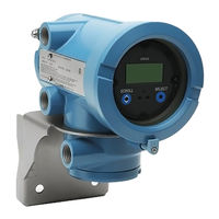
Emerson MICRO MOTION 1500 Configuration And User Manual (146 pages)
Transmitters with the Filling and Dosing Application
Brand:
Emerson
| Category:
Transmitter
| Size: 1.56 MB
Table of Contents
Table of Contents
3
Chapter 1 Before You Begin
9
Overview
9
Safety
9
Version
9
Flowmeter Documentation
9
Communication Tools
10
Planning the Configuration
10
Pre-Configuration Worksheet
11
Micro Motion Customer Service
12
Chapter 2 Connecting with Prolink II Software
13
Overview
13
Requirements
13
Prolink II Configuration Upload/Download
13
Connecting from a PC to a Model 1500 Transmitter
14
Chapter 3 Flowmeter Startup
17
Overview
17
Applying Power
17
Performing a Loop Test
18
Trimming the Milliamp Output
19
Zeroing the Flowmeter
20
Preparing for Zero
21
Zero Procedure
21
Chapter 4 Required Transmitter Configuration
23
Overview
23
Characterizing the Flowmeter
24
When to Characterize
24
Characterization Parameters
24
How to Characterize
26
Configuring the Channels
27
Configuring the Measurement Units
28
Mass Flow Units
28
Volume Flow Units
29
Density Units
30
Temperature Units
30
Pressure Units
30
Configuring the Ma Output
30
Configuring the Primary Variable
32
Configuring the Ma Output Range (LRV and URV)
32
Configuring the AO Cutoff
32
Configuring the Fault Action, Fault Value, and Last Measured Value Timeout
33
Configuring Added Damping
33
Configuring the Discrete Output(S)
34
Configuring the Discrete Input
37
Establishing a Meter Verification Baseline
37
Chapter 5 Using the Transmitter
39
Overview
39
Recording Process Variables
39
Viewing Process Variables
40
Viewing Transmitter Status and Alarms
40
Using the Status LED
40
Using Prolink II Software
40
Using the Totalizers and Inventories
41
Chapter 6 Optional Transmitter Configuration
43
Overview
43
Default Values
43
Parameter Location Within Prolink II
43
Creating Special Measurement Units
43
About Special Measurement Units
44
Special Mass Flow Unit
44
Special Volume Flow Unit
45
Special Unit for Gas
45
Configuring Cutoffs
46
Cutoffs and Volume Flow
46
Interaction with the AO Cutoff
46
Configuring the Damping Values
47
Damping and Volume Measurement
47
Interaction with the Added Damping Parameter
47
Interaction with the Update Rate
48
Configuring the Update Rate
48
Effects of Special Mode
49
Configuring the Flow Direction Parameter
49
Configuring Events
53
Configuring Slug Flow Limits and Duration
54
Configuring Fault Handling
55
Changing Status Alarm Severity
55
Changing the Fault Timeout
57
Configuring Digital Communications
57
Changing the Digital Communications Fault Indicator
57
Changing the Modbus Address
58
Changing the RS-485 Parameters
58
Changing the Floating-Point Byte Order
59
Changing the Additional Communications Response Delay
59
Configuring Variable Mapping
59
Configuring Device Settings
60
Configuring Sensor Parameters
60
Chapter 7 Configuring the Filling and Dosing Application
61
About this Chapter
61
User Interface Requirements
61
About the Filling and Dosing Application
61
Purge
64
Cleaning
64
Configuring the Filling and Dosing Application
64
Flow Source
67
Filling Control Options
68
Valve Control Parameters
69
Overshoot Compensation
70
Configuring Overshoot Compensation
72
Standard AOC Calibration
72
Rolling AOC Calibration
73
Chapter 8 Using the Filling and Dosing Application
75
About this Chapter
75
User Interface Requirements
75
Operating the Filling and Dosing Application from Prolink II
75
Using the Run Filler Window
76
Using a Discrete Input
78
Fill Sequences with PAUSE and RESUME
80
Chapter 9 Pressure Compensation
85
Overview
85
Pressure Compensation
85
Options
85
Pressure Correction Factors
85
Pressure Measurement Unit
86
Configuration
86
Chapter 10 Measurement Performance
89
Overview
89
Meter Validation, Meter Verification, and Calibration
89
Meter Verification
89
Meter Validation and Meter Factors
90
Calibration
90
Comparison and Recommendations
91
Performing Meter Verification
91
Specification Uncertainty Limit and Test Results
93
Additional Prolink II Tools for Meter Verification
94
Performing Meter Validation
94
Performing Density Calibration
95
Preparing for Density Calibration
95
Density Calibration Procedures
96
Performing Temperature Calibration
98
Chapter 11 Troubleshooting
99
Overview
99
Guide to Troubleshooting Topics
99
Micro Motion Customer Service
100
Transmitter Does Not Operate
100
Transmitter Does Not Communicate
100
Zero or Calibration Failure
100
Fault Conditions
100
I/O Problems
101
Transmitter Status LED
102
Status Alarms
103
Checking Process Variables
106
Meter Fingerprinting
109
Troubleshooting Filling Problems
109
Diagnosing Wiring Problems
110
Checking the Power Supply Wiring
110
Checking the Sensor-To-Transmitter Wiring
110
Checking Grounding
110
Checking for RF Interference
111
Checking Prolink II
111
Checking the Output Wiring and Receiving Device
111
11.17 Checking Slug Flow
111
11.18 Checking Output Saturation
112
11.19 Checking the Flow Measurement Unit
112
11.20 Checking the Upper and Lower Range Values
112
11.21 Checking the Characterization
113
11.22 Checking the Calibration
113
11.23 Checking the Test Points
113
Obtaining the Test Points
113
Evaluating the Test Points
113
Excessive Drive Gain
114
Sensor Pickoff Values
114
Erratic Drive Gain
115
Low Pickoff Voltage
115
Checking the Core Processor
115
Checking the Core Processor LED
116
Core Processor Resistance Test
117
Checking Sensor Coils and RTD
118
Remote Core Processor with Remote Transmitter Installation
118
4-Wire Remote Installation
120
A.1 Overview
123
Appendix A Default Values and Ranges
123
Overview
123
Default Values and Ranges
123
B.1 Overview
127
Appendix B Installation Architectures and Components
127
Overview
127
Installation Diagrams
127
Component Diagrams
127
B.2 Installation Diagrams
127
B.3 Component Diagrams
127
B.4 Wiring and Terminal Diagrams
127
Wiring and Terminal Diagrams
127
Appendix C Menu Flowcharts
133
Overview
133
Version Information
133
Flowcharts
133
C.1 Overview
133
C.2 Version Information
133
C.3 Flowcharts
133
Appendix Dne53 History
137
Overview
137
Software Change History
137
D.1 Overview
137
D.2 Software Change History
137
Advertisement
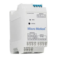
Emerson MICRO MOTION 1500 Installation Manual (92 pages)
MVD Transmitters
Brand:
Emerson
| Category:
Transmitter
| Size: 16.23 MB
Table of Contents
Table of Contents
3
October 2018 MMI
6
Chapter 1 Planning the Installation
7
About this Document
7
Installation Architecture
7
Hazardous Area Installations
8
Chapter 2 Transmitter Output Installation
9
Transmitter Output Installation: Analog Outputs for Model 1700/2700 Transmitters
10
Transmitter Output Installation Model 2750 Transmitter with Configurable Inputs and Outputs
11
Transmitter Output Installation: Model 2700 with Configurable Inputs and Outputs
12
Transmitter Output Installation: Profibus-PA Outputs for Model 1700/2700 Transmitters
13
Transmitter Output Installation Model 1700/2700 with Intrinsically Safe Installation
14
Transmitter Output Installation Model 1700/2700 with Fieldbus
15
Chapter 3 Model 1700/2700 4-Wire Installation
17
Model 1700/2700 4-Wire Installation: Remote Transmitter to Enhanced Core Processor Mounted on Sensor
18
Model 1700/2700 Transmitter 4-Wire Installation - Remote Transmitter to Core Processor Mounted on Sensor
19
Model 1700-2700 Transmitter 4-Wire Remote Transmitter Installation to Core Processor Mounted on CMF400 Sensor with Booster Amplifier
20
Model 1700/2700 Transmitter 4-Wire Remote Transmitter to Core Processor Mounted on D600 Sensor
21
Chapter 4 Direct Host 4-Wire Installation
23
Direct Host 4-Wire Installation - Core Processor to Direct Host through a Safety Barrier
24
Direct Host 4-Wire Installation of Enhanced Core Processor to a Direct Host through a Safety Barrier
25
Chapter 5 Model 800 Enhanced Core Processor
27
Chapter 6 Model 2750 4-Wire Installation
29
Chapter 7 Model 1500/2500 4-Wire Installation
31
Remote Transmitter to Enhanced Core Processor Mounted on Sensor
32
Remote Transmitter to Core Processor Mounted on CMF, F, H, R, CNG, and T Sensor
33
Remote Transmitter to Core Processor Mounted on CMF400 Sensor with Booster Amplifier
34
Remote Transmitter to Core Processor Mounted on D600 Sensor
35
Chapter 8 Model 3700 Transmitter 4-Wire Installation
37
Model 3700 Transmitter to Enhanced Core Processor Mouted on Sensor
38
Model 3700 Transmitter to Core Processor Mounted on CMF, F, H, R, CNF, and T Sensors
39
Remote Model 3700 Transmitter to Core Processor Mounted on CMF400 Sensor with Booster Amplifier
40
Model 3700 Remote Transmitter to Core Processor Mounted on D600 Sensor
41
Chapter 9 Model 3500 Transmitter 4-Wire Installation
43
Remote Model 3500 Transmitter to Enhanced Core Processor Mounted on Sensor
44
Remote Model 3500 Transmitter to Core Processor Mounted on CMF, F, H, R, CNG and T Sensors
45
Remote Model 3500 Transmitter to Core Processor Mounted on CMF400 Sensor with Booster Amplifier
46
Remote Model 3500 Transmitter to Core Processor Mounted on D600 Sensor
47
MMI-20001965 October
27
Chapter 10 Model LFT 4-Wire Installation to LF Sensor
49
Profibus-PA Transmitter Remotely Mounted to LF Sensor
50
Ma/Fo Transmitter Remotely Mounted to LF Sensor
51
FOUNDATION Fieldbus ™ Transmitter Remotely Mounted to LF Sensor
52
Config I/O Transmitter Remotely Mounted to LF Sensor
53
DIN Rail Transmitter Remotely Mounted to LF Sensor
54
Chapter 11 Model 1700/2700 Transmitter 9-Wire Integral Installations
55
Model 1700/2700 Transmitter with Integrally-Mounted Processor to Junction Box on CMF, F, H, T, D, and DL Sensors
56
Model 1700/2700 Transmitter with Integrally-Mounted Core Processor to 9-Wire Junction Box on CMF400 Sensor with Booster Amplifier
57
Model 1700/2700 Transmitter with Integrally-Mounted Core Processor to Junction Box on D600 Sensor
58
Model 1700/2700 Transmitter with Integrally-Mounted Core Processor to 9-Wire Junction Box on DT Sensor
59
Chapter 12 Model 1700/2700 9-Wire Remote Installations
61
Model 1700/2700 Transmitter Installation to Remote Core Processor to 9-Wire Junction Box on CMF, F, T, D, and DL Sensors
62
Model 1700/2700 Transmitter to Remote Mount Core Processor to 9-Wire Junction Box on CMF400 Sensor with Booster Amplifier
63
Model 1700/2700 Transmitter to Remote Core Processor to 9-Wire Junction Box on D600 Sensor
64
Model 1700/2700 Transmitter to Remote Core Processor to 9-Wire Junction Box on DT Sensor
65
Chapter 13 Model 1500/2500 9-Wire Installation
67
Model 1500/2500 Transmitter to Remote Mount Core Processor to 9-Wire Junction Box on CMF, D (Except D600), DL, F, H, and T Sensors
68
Model 1500/2500 Transmitter to Remote Core Processor to 9-Wire Junction Box on CMF400 Sensor with Booster Amplifier
69
Model 1500/2500 Transmitter to Core Processor to 9-Wire Junction Box on D600 Sensor
70
Model 1500/2500 Transmitter to Core Processor to 9-Wire Junction Box on DT Sensor
71
Chapter 14 Model 3700 9-Wire Installation Instructions
73
Model 3700 Transmitter to Remote Mount Core Processor to 9-Wire Junction Box on CMF, D (Except D600), DL, F, H, and T Sensors
74
Model 3700 Transmitter to Remote Core Processor to 9-Wire Junction Box on CMF400 Sensor with Booster Amplifier
75
Model 3700 Transmitter to Remote Core Processor to 9-Wire Junction Box on D600
76
Model 3700 Transmitter to Remote Mount Core Processor to 9-Wire Junction Box on DT Sensor
77
Chapter 15 Model 3500 9-Wire Installation
79
Model 3500 Transmitter to Remote Core Processor to 9-Wire Junction Box on CMF, D (Except D600), DL, H, and T Sensors
80
Model 3500 Transmitter to Remote Core Processor to 9-Wire Junction Box on CMF400 Sensor with Boost Amplifier
81
Model 3500 Transmitter to Remote Mount Core Processor to 9-Wire Junction Box on D600 Sensor
82
Model 3500 Transmitter to Remote Mount Core Processor to 9-Wire Junction Box on DT Sensor
83
Chapter 16 D600 Remote Booster Amplifier Installation
85
D600 Remote Booster Amplifier Installation with Core Processor Remotely Mounted from Sensor and Transmitter
86
D600 Remote Booster Amplifier with Junction Box Remotely Mounted from Sensor and Transmitter
87
Emerson MICRO MOTION 1500 User Manual (106 pages)
Liquid Turbine Meter
Brand:
Emerson
| Category:
Measuring Instruments
| Size: 4.44 MB
Table of Contents
Table of Contents
3
Part I Plan
5
Chapter 1 Introduction
7
Purpose of this Manual
7
Hazard Messages
7
Personnel Qualifications
7
Warranty Restrictions
9
Assistance
9
Description of the Series 1500 Liquid Turbine Meter (LTM)
10
Agency Certifications for the Series 1500 LTM
31
Chapter 2 Operating Conditions and Specifications
33
Operating Conditions for the Liquid Turbine Meter
33
Specifications for the LTM
38
Chapter 3 Turbine Meter Handling
47
Receive the Turbine Meter
47
Store the Turbine Meter
47
Chapter 4 Prepare the Turbine Meter for Use
49
Lifting Conditions
49
Lifting Requirements for Personnel
50
Configuration of the Turbine Meter
53
Part II Install
61
Chapter 5 Installation Prerequisites
63
Pre-Start Checks
63
Torque Information
63
Tools Required for LME Disassembly/Assembly
63
Chapter 6 Installation Procedure
65
Cathodic Protection
65
Mechanical Components Assembly
65
Assemble the Electronic Components
66
Chapter 7 Testing
69
Test the Turbine Meter
69
Chapter 8 Operation Parameters
73
Operation Overview
73
Part IV Maintain
75
Chapter 9 Planned Maintenance
77
Maintenance Considerations
77
Tools Required for Mechanical Components
77
Prepare for Mechanical Disassembly
78
Mechanical Assembly
87
Electronics Enclosure Disassembly
94
Electronics Enclosure Assembly
95
Replace the Preamplifier
96
Planned Maintenance Tasks
97
Chapter 10 Corrective Maintenance
99
Turbine Meter Troubleshooting
99
Verify the Return to Operational Condition
99
Chapter 11 Spare Parts
101
Recommended Spare Parts
101
Chapter 12 Decommission the Turbine Meter
103
Shut down the Turbine Meter
103
Turbine Meter Disassembly/Assembly
103
Shipment of the Meter
104
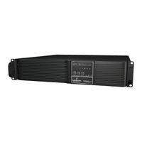
Emerson MICRO MOTION 1500 User Manual (32 pages)
Brand:
Emerson
| Category:
Power Supply
| Size: 1.65 MB
Table of Contents
Table of Contents
3
Important Safety Instructions
5
Save These Instructions
5
Glossary of Symbols
7
1 Introduction
8
Figure 1 Front View of UPS
8
Figure 2 1000 and 1500-Rear View
8
Figure 3 2200-Rear View
9
Figure 4 3000-Rear View
9
2 What S Included
10
Accessories
10
What' Included
10
Figure 5 Accessories
10
3 Installation
11
Preparation
11
Figure 6 Placing the Liebert PSI XR
11
Tower UPS Installation
12
Figure 7 Tower Configuration-Attach Tower Stands
12
Rack-Mount UPS Conversion and Installation
13
Figure 8 Convert the Liebert PSI XR for Rack Installation
13
Orient Display for Installation
14
Charge Batteries and Perform Battery Startup
14
Connect Input Power and Load
14
Figure 9 Orienting the UPS Display
14
Figure 10 Connect Input Power and Load
14
Connect Network Surge Protection
15
Connect Communication Interface
15
Figure 11 Connect Network Surge Protection
15
Figure 12 Connect Communication Interface
15
Set up Liebert Multilink Software
16
EPO Switch
16
Figure 13 EPO Connection for Normally Open Operation
16
External Battery Cabinet Installation
17
Figure 14 Install the External Battery Cabinet in Tower Installation
17
Table 1 Battery Cabinet Connector Color Key
17
Figure 15 Connect Battery Cabinets to UPS
18
4 Controls and Indicators
19
Figure 16 Display and Status Indicators
19
Table 2 Display and Status Indicators Function, Legend
19
Control Buttons
20
On/Alarm Silence/Manual Self-Diagnostic Test
20
Off Button
20
Status Indicators
20
Status Change Button
20
Load Level Indicator
20
Battery Level Indicator
21
UPS Status Indicators
21
Table 3 Status Indicators-Color, Illumination Mode
21
Table 3
21
5 Operational Modes
22
Normal Mode
22
Buck/Boost Mode
22
Battery Mode
22
Battery Recharge Operation
22
6 Communication
23
DB-9 Connector
23
Remote Shutdown Via the DB-9 Connector
23
Any Mode Shutdown Via Pins 5 & 6
23
Battery Mode Shutdown Via Pins 4 & 5
23
Network Surge Protection Connectors
23
Pin Assignment
23
Table 4 DB-9 Pin Assignment
23
UPS Communications
24
UPS Inverter/Transfer Voltage Configurations
24
Figure 17 DIP Switch Settings for 120V System
24
Voltage Configurations
24
Table 5 Voltage Configurations
24
7 Battery Maintenance
25
Battery Charging, Storage
25
Internal Battery Replacement Procedure
25
Figure 18 Battery Replacement
25
8 Pecifications
26
Liebert PSI XR Specifications
26
Table 6 Liebert PSI XR Specifications
26
Battery Cabinet Specifications
27
Table 7
27
Table 8 Liebert PSI XR Battery Run Times
28
Emerson MICRO MOTION 1500 Installation Manual (60 pages)
Brand:
Emerson
| Category:
Transmitter
| Size: 4.02 MB
Table of Contents
Table of Contents
3
Chapter 1 Planning
5
Meter Components
5
Installation Types
5
Maximum Cable Lengths between Sensor and Transmitter
7
Output Options
8
Environmental Limits
9
Hazardous Area Classifications
9
Power Requirements
9
Chapter 2 Mounting and Sensor Wiring for 4-Wire Remote Installations
11
Mounting the Transmitter to a DIN Rail
11
Prepare the 4-Wire Cable
12
Wire the Transmitter to the Sensor
15
Ground the Flowmeter Components
16
Chapter 3 Mounting and Sensor Wiring for Remote Core Processor with Remote Sensor Installations
17
Mounting the Transmitter to a DIN Rail
17
Mount the Remote Core Processor
18
Prepare the 4-Wire Cable
19
Wire the Transmitter to the Remote Core Processor
22
Prepare the 9-Wire Cable
23
Wire the Remote Core Processor to the Sensor Using Jacketed Cable
29
Wire the Remote Core Processor to the Sensor Using Shielded or Armored Cable
32
Ground the Meter Components
36
Chapter 4 Wiring the Power Supply
38
Wire the Power Supply
38
Chapter 5 I/O Wiring for Model 1500 Transmitters
39
Basic Analog Wiring
39
Hart/Analog Single Loop Wiring
39
HART Multidrop Wiring
40
Internally Powered Frequency Output Wiring
41
Chapter 6 I/O Wiring for Model 2500 Transmitters
42
Ma/Hart Wiring
42
Frequency Output Wiring
44
Discrete Output Wiring
47
Discrete Input Wiring
50
Chapter 7 Specifications
51
Electrical Connections
51
Input/Output Signals
52
Environmental Limits
55
Physical Specifications
56
Index
59
Emerson MICRO MOTION 1500 Product Data Sheet (28 pages)
Micro Motion 3000 Series Transmitters and Discrete Controllers
Brand:
Emerson
| Category:
Transmitter
| Size: 0.91 MB
Table of Contents
Table of Contents
3
Housings
4
Applications
4
Interface/Display
5
Electrical Connections
5
Input Signals
6
Output Signals
6
Environmental Specifications
8
Power Supply
8
Hazardous Area Classifications
9
Model 3100 Accessory
10
Model 3500/3700 Liquid Flow Performance
10
Model 3500/3700 Density Performance (Liquid Only)
11
Model 3500/3700 Gas Flow Performance
11
Weight
11
Dimensions
12
Ordering Information
16
Advertisement
Related Products
Emerson Micro Motion 1700
Emerson Rosemount 1066
Emerson Rosemount 1152 Alphaline
Emerson Rosemount 1154
Emerson Rosemount 1151
Emerson Rosemount 148
Emerson Rosemount 1408H
Emerson Rosemount 1408A
Emerson Rosemount 1208A
Emerson Rosemount 1208C
Emerson Categories
Controller
Control Unit
Transmitter
Measuring Instruments
Fan
More Emerson Manuals
Login
Sign In
OR
Sign in with Facebook
Sign in with Google
Upload manual
Upload from disk
Upload from URL