Sign In
Upload
Manuals
Brands
Eaton Manuals
DC Drives
M-Max series
Eaton M-Max series Manuals
Manuals and User Guides for Eaton M-Max series. We have
4
Eaton M-Max series manuals available for free PDF download: User Manual, Operating Instructions Manual, Quick Start Manual
Eaton M-Max series User Manual (204 pages)
Adjustable Frequency Drive
Brand:
Eaton
| Category:
Inverter
| Size: 1.43 MB
Table of Contents
Table of Contents
5
Safety
12
Before Commencing the Installation
12
Definitions and Symbols
13
Hazardous High Voltage
13
Warnings and Cautions
13
About this Manual
17
Writing Conventions
17
Abbreviations and Symbols
17
Input Supply Voltages
18
Units
18
Unit Conversion Examples
18
M-Max Series Overview
19
Notes on the Second MMX Upgrade
19
M-Max Frequency Converter
19
Control Signal Terminals and Microswitches
19
Component Identification
20
M-Max Series
20
Checking the Delivery
21
Scope of Supply
21
Nameplate Rating Data
22
Nameplate Inscriptions
22
Catalog Number Selection
23
Type Designation of the M-Max Frequency Inverters
23
Examples
24
Technical Data and Specifications
25
General Rated Operational Data
25
Power Connection Voltages
27
Description of the M-Max
29
Features
29
Overview of the M-Max Device (FS1-FS3)
29
Overview of the M-Max Device (FS4 and FS5)
29
Block Diagram, Elements of M-Max Frequency Inverters
30
Selection Criteria
31
Proper Use
32
Maintenance and Inspection
32
Maintenance Measures and Intervals
32
Storage
33
Charging DC Link Capacitors
33
Service and Warranty
33
Engineering
34
Introduction
34
Drive System (PDS)
34
Electrical Power Network
35
AC Power Networks with Grounded Center Point (TN-/TT Networks)
35
Safety and Switching
37
Identification on the Residual-Current Circuit-Breakers
37
EMC Measures
38
EMC Environment and Category
38
Motor and Application
39
Parallel Connection of Several Motors to One Frequency Inverter
39
Example of a Motor Ratings Plate
40
Star and Delta Circuit Types
40
V/Hz-Characteristic Curve
40
Assignment of Frequency Inverters to Example Motor Circuit
40
Bypass Motor Control (Example)
41
Installation
42
Introduction
42
Installation Instructions
42
Mounting Position (FS1-FS3)
42
Mounting Position (FS4 and FS5)
42
Air-Cooling Space
43
Minimum Clearance at the Front
43
Air-Baffle Due to Increased Circulation with Device Fan
43
Minimum Clearance and Required Cooling Air
43
Mounting Dimensions
44
Configuration for Mounting with Screws
44
Mounting Rail Conforming with IEC/EN 60715
45
Fastening to the Mounting Rail
45
Demounting
45
Mounting the Cable Routing Plate and the Brackets
45
EMC Installation
46
EMC-Compliant Setup (Example: M-Max)
47
Electrical Installation
48
Three-Phase Input Connection
49
Connection to Power Section
49
Ground Connection
49
Connection in Power Section
50
Stripping Lengths in the Power Section in Inches (MM)
50
Screened Connection Cable
51
Connection with Twisted Cable Shielding
51
Four-Core Shielded Motor Supply Cable
51
Arrangement and Size of the Connection Terminals
52
Position of Control Signal Terminals
54
Prevent the Shield from Becoming Unbraided
54
Example for a Single-Side Connection (PES) to the Frequency Inverter
54
Example for an Insulated End of the Control Cable
54
Control Signal Terminals Assignments and Designations
55
Microswitch Factory Settings
55
Possible Connection Line Sizes and Specifications on Control Signal Terminals
55
Factory-Set Control Terminal Functions
56
Control Signal Terminals (Digital and Analog Inputs/Outputs)
57
Analog Setpoint Inputs AI1 and AI2
57
Analog Setpoint Value Signal, for Example, from a Superordinate Controller (PLC)
57
Analog Output AO (Connection Examples)
58
Digital Inputs with Internal Supply Voltage
58
Digital Inputs with External Supply Voltage
58
Digital Inputs with Internal Supply Voltage (Negative Logic, Sink Type)
58
Digital Inputs with External Supply Voltage (Negative Logic, Sink Type)
59
Digital Output DO and Connection Examples
59
Connection Example and Operation of DO in Source and Sink Type
59
Relay Outputs with Connection Examples, Control Relay
60
With Suppressor Circuit
60
Fixed Connection Cables at U >48V (Relay)
60
Connection Terminals of the Serial Interface and Microswitch S4
61
(Bus Terminating Resistor)
61
Two-Wire RS485 Connection
61
Mmx11
62
Mmx12
63
MMX32, MMX34 and MMX35 Block Diagram
64
Operation
66
Commissioning Checklist
66
Operational Hazard Warnings
67
Commissioning with Control Signal Terminals (Factory Setting)
68
Operational Data Indicator (Operational)
69
Operation (RUN) Via Control Signal Terminal (I/O) with
69
Left Rotating Field (REV) (for Example, -12.34 Hz)
69
Start-Stop Command with Maximum Setpoint Value
70
Voltage, Acceleration Ramp 3S
70
Brief Instructions: Steps to the Motor Start
71
Error and Warning Messages
72
Introduction
72
Example of an Error Message (Undervoltage)
72
Example of an Alarm Message
72
List of Fault Messages (F) and Warning Messages (AL)
73
Error Messages Via Operating Unit
75
Control Unit
76
Parameters
76
View of the Keypad with LCD Display, Function Keys
76
And Interface (LCD = Liquid Crystal Display)
76
Control Unit Elements
76
LCD Display (Areas)
77
Operational Data Indicator (Operational)
77
Areas of the LCD Display
77
Setting Parameters
78
Parameter Menu (PAR)
80
Parameter Menu (P1.1 = 1, Quick Configuration)
80
Schematic Representation of Parameter Access
80
Predefined Application Parameters from Parameter P1.2
82
Default I/O
83
Parameter Selections
83
Analog Inputs AI1 and AI2
84
Analog Inputs
84
Example of Scaled Analog Input Signals
85
Example of Scaled Analog Input Signals with Offset
85
Filter Time Constant
86
Digital Inputs for Source and Sink Type
87
Control Logic Reaction to a Rising or Falling Edge (Source Type, Sink Type)
87
Digital Inputs
88
Di1 (Fwd) + Di2 = Rev
92
Example: Start Stop Impulse
92
Analog Output AO
93
Analog Outputs
93
Digital Outputs
94
Drives Control
98
Acceleration and Deceleration Time
99
S-Formed Curve for Acceleration and Deceleration Ramps
100
Automatic Restart after Error Message (Two Start Attempts)
101
Motor Parameters from Ratings Plate
104
Circuits (Delta, Star)
104
Motor
105
Protective Functions
106
Motor Cooling Power
108
Calculation of Motor Temperature
108
PID Controller
111
Function Chart for OD (PID System Deviation)
114
PID Controller, Actual Value Message FBV
115
Block Diagram, Ventilation with "Two-Stage Control
115
Fixed Frequencies FF1, FF2 and FF3 (= FF1 + FF2)
116
Example: Activation of the Fixed Frequencies in the Factory Setting with Acceleration and Deceleration Ramps
116
Fixed Frequency
116
Fixed Frequency Setpoint Value
117
Determining the Program Number (P10.10)
118
Fixed Frequency Setpoint Value
119
Example A, Program Cycle Executed Once (P10.9 = 1, P10.10 = 0)
120
Example B, Program Cycle Executed Once (P10.9 = 1, P10.10 = 192)
121
Example C, Program Cycle Executed Once in Steps (P10.9 = 2, P10.10 = 0)
122
V/Hz-Characteristic Curve
123
V/Hz-Characteristic Curve (P11.1)
124
Speed Behavior Without Slip Compensation
126
Equivalent Circuit Diagram for an Asynchronous Motor
126
Speed Behavior with Slip Compensation
126
Braking
128
Regenerative Braking with External Braking Resistor
131
Mechanical Brake
133
Logic Linking of a and B
134
Logic Function
135
Second Parameter Set
137
Roller Conveyor with Rotary Table
139
Stop Function with Two Different Deceleration Times
140
System Parameter
141
Operational Data Indicator (MON)
143
Operational Data Indicator
143
Status Displays Examples
144
Setpoint Input (REF)
145
Serial Interface (Modbus Rtu)
147
General Information about Modbus
147
Communications in a Modbus Network
147
Modbus Network with M-Max
147
Modbus Parameters
148
Modbus Parameters in the M-Max
148
Data Exchange between Master and Slave
149
Error Code Description
151
Modbus Process Data
153
Appendix A
158
Device Series MMX11
158
Special Technical Data
158
Device Series MMX12
159
Device Series MMX32
160
Device Series MMX34
161
Device Series MMX35
163
Dimensions and Frame Sizes
164
Dimensions and Frame Sizes, FS1-FS3 (FS = Frame Size)
164
Dimensions and Frame Sizes, FS4 and FS5 (FS = Frame Size)
165
Dimensions and Frame Sizes
166
PC Interface Card
167
Equipment Supplied MMX-COM-PC
167
Fitting the MMX-COM-PC Connection Module
167
Removing the MMX-COM-PC Connection Module
167
Download
168
Inserting the 9V Block Battery
168
Mounting Frame for Fieldbus Connection
169
Upload
168
MMX-NET-XA Mounting Frame
169
Parameter Software Maxconnect
169
Power Supply
169
Removing the Interface Cover on the M-Max
169
Connecting the Interface Card with the Frequency Inverter
170
Cover of the MMX-NET-XA for Holding the Fieldbus Interface Card
170
Fitting and Connecting the Mounting Plate of the MMX-NET-XA
170
MMX-NET-XB Interface Module
171
Mounting Accessories for FS4, FS5
171
Plastic Bridge for Holding the Control Terminals
171
Remove Cover (FS4, FS5)
171
Connecting the MMX-NET-XB Interface Module with
172
The Fieldbus Interface Cards
172
PROFIBUS DP Fieldbus Interface Card
173
Fieldbus Connection
173
XMX-NET-DN-A Devicenet Fieldbus Interface Card
173
Cables, Fuses and Disconnect Devices
174
XMX-NET-PD-A PROFIBUS DP Fieldbus Interface Card with Nine-Pole Sub-D Plug Connection
173
Fuses and Maximum Cross-Sections
175
Specified Fuses and Disconnect Devices
176
List of Parameters
177
Quick Start Parameter Guide
177
System Parameters in the Quick Start
178
Default I/O
179
Analog Input
180
Parameter Selection
180
Digital Input
181
Analog Output
182
Digital Output
183
Drives Control
184
Motor
186
Protective Functions
186
PID Controller
187
Fixed Frequencies
188
V/Hz-Characteristic Curve
189
Braking
190
Logic Function
191
Second Parameter Set
192
System Parameters
193
Parameter Values Currently Being Measured
195
Appendix B
196
Door Panel Keypad Adapter System-Mounting Instructions
196
Door Keypad Components
196
Door Keypad Mounting Kit
196
Door Keypad Mounting Instructions
197
Door Keypad Mounting Instructions, Continued
198
Door Keypad Cut-Out Dimensions
199
Door Keypad Dimensions
200
Advertisement
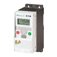
Eaton M-Max series Operating Instructions Manual (199 pages)
Adjustable Frequency Drive
Brand:
Eaton
| Category:
DC Drives
| Size: 8.68 MB
Table of Contents
Table of Contents
5
Notes on the Second MMX Upgrade
9
Writing Conventions
10
Abbreviations and Symbols
11
Mains Supply Voltages
11
Units
11
System Overview
13
Checking the Delivery
14
Rating Data on the Nameplate
15
Key to Part Numbers
16
General Rated Operational Data
18
Technical Data
20
Description of the M-Max TM
22
Features
22
Selection Criteria
24
Proper Use
25
Maintenance and Inspection
26
Storage
26
Charging DC Link Capacitors
26
Service and Warranty
26
Introduction
27
Electrical Power Network
28
Mains Connection and Configuration
28
Mains Voltage and Frequency
28
Voltage Balance
28
Idle Power Compensation Devices
29
Mains Reactors
29
Safety and Switching
30
Fuses and Cable Cross-Sections
30
Cables and Fuses
30
Residual-Current Device (RCD)
30
Mains Contactor
31
EMC Measures
31
Motor and Application
32
Motor Selection
32
Connecting Motors in Parallel
32
Motor and Circuit Type
33
Bypass Operation
34
Connecting EX Motors
34
Introduction
35
Installation Instructions
35
Mounting Position
35
Cooling Measures
35
Fixing
36
EMC Installation
39
EMC Measures in the Control Panel
39
Earthing
39
Screen Earth Kit
39
Electrical Installation
41
Connection to Power Section
42
Arrangement and Connection of the Power Terminals
44
Connection on Control Section
46
Arrangement and Connection of the Control Signal Terminals
47
Microswitches and Control Signal Terminals
47
Function of the Control Signal Terminals
48
Block Diagram
54
Insulation Testing
57
Operation
59
Checklist for Commissioning
59
Operational Hazard Warnings
60
Commissioning with Control Signal Terminals (Factory Setting)
61
Brief Instructions
64
Error and Warning Messages
67
Introduction
67
Error Messages
67
Acknowledge Fault Message (Reset)
67
Fault Log (FLT)
67
Alarm Messages
67
Parameters
71
Control Unit
71
Display Unit
72
General Information on Menu Navigation
72
Setting Parameters
73
Parameter Menu (PAR)
75
Quickstart Wizard
76
Parameter Selection (P1)
77
Analog Input (P2)
79
Digital Input (P3)
82
Analog Output (P4)
87
Digital Output (P5)
88
Drives Control (P6)
92
Motor (P7)
98
Protective Functions (P8)
99
PID Controller (P9)
104
Fixed Frequency Setpoint Value (P10)
108
U/F-Characteristic Curve (P11)
115
Braking (P12)
120
Logic Function (P13)
125
Second Parameter Set (P14)
128
System Parameter
132
Operational Data Indicator (MON)
134
Setpoint Input (REF)
136
Serial Interface (Modbus RTU)
139
General Information about Modbus
139
Communications in a Modbus Network
139
Modbus Parameters
140
Operating Mode Modbus RTU
141
Structure of the Master Request
142
Data Storage with Modbus
144
Modbus-Register-Mapping
144
Modbus Process Data
145
Explanation of Function Code
148
Appendix
151
Special Technical Data
151
Device Series MMX11
151
Device Series MMX12
152
Device Series MMX32
153
Device Series MMX34
154
Dimensions and Frame Size
155
MMX-Com-Pc
157
PC Interface Module
157
MMX-Net-Xa
158
Mounting Frame for Fieldbus Connection
158
XMX-Net-Co-A
159
XMX-Net-Pd-A, XMX-Net-Ps-A
160
PROFIBUS DP Fieldbus Interface Card
160
Cables and Fuses
161
Mains Contactors
163
Radio Interference Suppression Filters
165
Special Technical Data for MMX-LZ
167
Dimensions and Sizes of the MMX-LZ
168
Brake Resistors
169
Brake Resistors BR1
170
Brake Resistors BR2
170
Mains Chokes
173
Motor Chokes
175
Sinusoidal Filters
177
List of Parameters
180
Quick Configuration (Basis)
180
All Parameters
183
Index
197
Eaton M-Max series Quick Start Manual (58 pages)
Adjustable frequency drive
Brand:
Eaton
| Category:
DC Drives
| Size: 0.76 MB
Table of Contents
Table of Contents
4
List of Figures
5
List of Tables
5
Safety
6
Definitions and Symbols
6
Hazardous High Voltage
6
Cautions
7
Notices
7
Danger and Dangerous Electrical Voltage
7
Before Commencing the Installation
7
M-Max Series
11
About this Manual
11
Notes about the M-Max Product Enhancement
11
Figure 2: Control Signal Terminals
12
Writing Conversions
13
Rated Operational Data on the Nameplate
14
Mains Voltages
14
Table 1: Nameplate Inscriptions
14
Table 2: General Rated Operational Data
15
Technical Data
17
Table 3: Technical Data
17
Control Signal Terminals
18
Table 4: Cable Cross Section (Cu): 0.5 - 1.5 MM
19
Block Diagram
20
Operation
23
Checklist for Commissioning
23
Hazard Warnings
24
Error and Warning Messages
26
Introduction
26
Error Messages
26
Acknowledge Fault Message (Reset)
26
Fault Log (FLT)
27
Alarm Messages
27
Table 5: List of Fault Messages (F) and Warning Messages (AL)
28
Parameters
30
Control Unit
30
Table 6: Control Unit Elements
30
Display Unit
32
Table 7: Areas of the LCD Display
32
General Information on Menu Navigation
33
Setting Parameters
34
Table 8: LCD Display in Operation
34
Parameter Menu (PAR)
36
Quick Start Wizard
38
Example: Motor Parameters (P7)
39
List of Parameters
40
Quick Configuration (Basis)
40
Table 9: Quick Configuration
40
Table 10: Predefined Application Parameters from Parameter P1.2
42
All Parameters
43
Table 11: All Parameters
43
Advertisement
Eaton M-Max series Quick Start Manual (40 pages)
Variable frequency drives. Pump Application
Brand:
Eaton
| Category:
DC Drives
| Size: 0.63 MB
Table of Contents
Table of Contents
1
Step 1-Safety Information
4
Step 2-M-Max Series Overview
7
Step 3-Technical Data
12
Step 4-Operation
16
Step 5-Error and Warning Message
18
Step 6-Parameters
21
Advertisement
Related Products
Eaton MMX11AA2D4 Series
Eaton MMX11AA4D8 Series
Eaton MMX12AA4D8 Series
Eaton MMX32AA2D4 Series
Eaton MMX32AA4D8 Series
Eaton MMX34AA3D3 Series
Eaton MMX34AA4D3 Series
Eaton MMX34AA2D4 Series
Eaton MMX34AA5D6 Series
Eaton MMX34AA7D6 Series
Eaton Categories
UPS
Circuit breakers
Industrial Equipment
Switch
Industrial Electrical
More Eaton Manuals
Login
Sign In
OR
Sign in with Facebook
Sign in with Google
Upload manual
Upload from disk
Upload from URL