Sign In
Upload
Manuals
Brands
Canon Manuals
Copier
iR105 Series
Canon iR105 Series Manuals
Manuals and User Guides for Canon iR105 Series. We have
2
Canon iR105 Series manuals available for free PDF download: Service Manual, Function Manual
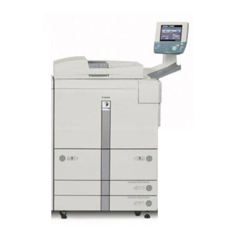
Canon iR105 Series Service Manual (1029 pages)
Brand:
Canon
| Category:
Copier
| Size: 17.67 MB
Table of Contents
Table of Contents
12
Safety of Toner
11
Chapter 1 Introduction
21
Features
22
Ease of Operation
22
High Durability, High Reliability
22
High Speed, High Quality
22
High-Performance Controller, Large-Capacity Hard Disk
22
Large-Capacity Paper Source
22
High-Level Printer Functions to Support Networking Requirements
23
Various Delivery Processing (with Options)
23
Specifications
24
Side Paper Deck-N1
35
Chapter 2 New Function
49
Basic Construction
49
Outline of the Basic Construction
49
Wiring Diagram of the Major Pcbs
50
Original Exposure System
51
Outline of the Original Exposure System
51
Enlargement/Reduction
53
Preventing Overheating of the Scanner Motor
54
Arrangement of Pcbs
55
Detecting the State (Open/Closed) of the ADF
56
Stabilizing the Scanning Lamp
56
Detecting Dust in Stream Reading
58
Disassembly/Assembly
60
No. 1 Mirror Base Assembly
61
Functions
64
Scanner Drive Assembly
65
Pcbs
72
Others
77
Image Processing System
85
Outline of the Image Processing System
85
Processing System
85
4-Channel High-Speed Reading CCD
87
CCD Adjustment
88
Analog Image Processing
89
Digital Image Processing
90
Detecting the Orientation of Originals
91
Disassembly/Assembly
92
CCD Unit
93
Hard Disk
95
Laser Exposure System
99
Outline of the Laser Exposure System
99
Disassembly/Assembly
102
Laser Unit
103
BD Unit
104
Image Formation System
107
Outline of the Image Formation System
107
Addition of the Developing Fan
110
Addition of the Pre-Transfer Exposure LED
110
Measures against Overheating of the Developing Unit
110
Modifying the Developing Cylinder Cover
111
Preventing Adhesion of Toner to the Cleaning Blade
112
Disassembly/Assembly
113
Process Unit
114
Drum Cleaner Unit
119
Charging Wires
122
Area Around the Process Unit
128
Pickup/Feeding System
131
Outline of the Pickup/Feeding System
131
Image Write Start Sensor
134
Optical Sensors
134
Index Paper Attachment
136
Disassembly/Assembly
137
Manual Feed Tray Assembly
138
Cassette Pickup Assembly
142
Vertical Path Roller Assembly
144
Registration Feed Assembly
147
Duplex Unit
148
Others
151
Fixing System
153
Outline of the Fixing System
153
Fixing Temperature Control
157
Transparency Mode
158
Thick Paper Mode
159
Power Save Mode
160
Detecting an Error
161
Down Sequence Control
162
Disassembly/Assembly
163
Fixing Heater and the Control Parts
164
Fixing Roller Assembly
170
Delivery Assembly
173
Paper Sensors
176
Fans
180
Sequence of Fan Operation
182
Disassembly/Assembly
184
External Covers
185
Control Panel
193
Fans
201
Drive Assembly
214
Switches
218
Pcbs
220
Others
232
Side Paper Deck-N1
235
Outline of the Side Paper Deck
235
Optical Sensors
238
Disassembly/Assembly
239
Removing the Deck Pickup Sensor Unit
240
Removing the Deck Feed Sensor Unit
241
Chapter 3 Main Controller
242
Basic Operation
243
Functional Construction
243
Hard Disk Drive
244
Main Controller PCB
244
Outline
244
Outline of the Electrical Circuitry
244
Outline
246
Start-Up Sequence
246
Start-Up Sequence
247
Construction of the System Software
248
Connection Diagram of the Major Pcbs
249
Inputs/Outputs the Major Pcbs
249
Digital Image Processing
250
Outline
250
Binary Processing (Error Diffusion Method T-BIC)
251
Density Conversion (LUT)
251
Edge Emphasis
251
Edit Processing
251
Enlargement/Reduction (Main Scanning Direction)
251
Image Data from the Reader Unit
251
Input Image Processing
251
Binary (Dither Screen Method)
252
Compression/Expansion, Rotation, and Enlargement/Reduction
252
Controlling the Image Memory
252
Sdram
252
Binary-Binary Conversion (Read Image Output Only)
253
Output Image Processing
253
Smoothing
253
Thickening (PDL Output Only)
253
Soft Counters
254
Controlling the Power Supply
256
Outline
256
Power Save Mode
256
Power Supply Mode
256
Standby Mode (Normal Operation)
256
Low Power Mode
257
Return to Standby Mode (Sleep → Standby)
257
Shift from Low-Power Mode (Low Power → Sleep)
257
Shift from Standby Mode (Standby → Low Power)
257
Shift from Standby Mode (Standby → Sleep)
257
Shift to Standby Mode (Low Power → Standby)
257
Sleep Mode
257
OFF Mode
258
Power Supply off Mode
258
Return to Standby Mode (off Mode → Standby)
258
Shift from Low-Power Mode (Low-Power → off Mode)
258
Shift from Standby Mode (Standby → off Mode)
258
Chapter 4 Installation
259
Selecting the Site
260
Unpacking and Installation
263
Points to Note before Starting the Work
263
Attachments
264
Unpacking
265
Mounting the Scanner
270
Installing the Fixing Assembly
271
Mounting the Charging Assemblies
273
Checking the Developing Assembly
278
Mounting the Pickup Assembly
280
Mounting the Control Panel
282
Supplying the Toner
288
Mounting the ADF
290
Cassette
291
Index Paper Attachment
292
Images/Operations, and User Mode
293
Changing the Paper Size for the Front Deck (Right, Left)
297
Relocating the Machine
299
Installing the Card Reader-D1
300
NE Controller-B1/Copy Data Controller-A1
305
Chapter 5 Maintenance and Inspection
309
Periodically Replaced Parts
310
Guide to Replacement of Durables
312
Copier
312
Side Paper Deck
316
Scheduled Service Chart
317
Scheduled Service Items
321
Scheduled Service Work
325
Work 2
328
Chapter 6 Troubleshooting
332
Guide to the Troubleshooting Tables
333
Image Adjustment Basic Procedure
335
Making Pre-Checks
335
Making Checks on the Printer Side (1/2)
336
Making Checks on the Printer Side (2/2)
337
Making Checks on the Scanner Side
338
Standards and Adjustments
341
Adjusting the Image Position for Printer Output
341
Adjusting the Image Position of Copier Output (Book Mode)
346
Adjusting the Image Position of Copier Output (ADF Mode)
349
Adjusting the Scanner Mirror Base
350
Replacing the Scanner Drive Cable
350
Scanning System
350
When Replacing the Scanning Lamp
350
When Replacing the Standard White Plate
350
Image Formation System
351
Mounting the Drum Cleaning Blade
351
Stringing the Charging Wire of the Charging Assemblies
351
Stringing the Grid Wire of the Primary Charging Assembly
351
Pickup/Feeding System
352
Orientation of the Deck/Cassette Pickup Roller
352
Orientation of the Deck/Cassette Separation Roller
353
Orientation of the Feeding Roller of the Deck/Cassette Pickup Assembly
353
Orientation of the Pickup Roller of the Manual Feed Tray/Side Paper Deck
354
Orientation of the Feeding Roller of the Manual Feed Tray
355
Orientation of the Feeding Roller of the Side Paper Deck
355
Adjusting the Pressure of the Deck/Cassette Separation Roller
356
Adjusting the Pressure of the Pickup/Feeding Roller of the Manual Feed Tray
357
Locations of the Solenoid
358
Location of the Fixing Web Solenoid (SL2)
359
Position of the Delivery Flapper Solenoid (SL3)
361
Position the Fixing/Feeder Unit Locking Solenoid (SL4)
362
Position of the Multifeeder Latch Solenoid (SL6)
363
Position of the Deck (Right) Pickup Solenoid (SL7)
364
Position of the Deck (Left) Pickup Solenoid (SL8)
365
Pickup Solenoid (SL9/10)
366
Fitting the Side Guide Timing Belt of the Manual Feed Tray Assembly
367
Position of the Side Paper Deck Pickup Roller Releasing Solenoid
367
Fitting the Drive Belt
368
Fixing System
369
Points to Note When Mounting the Fixing Heater
369
Adjusting the Lower Roller Pressure (Nip)
370
Laser Exposure System
371
Checking the Laser Power
371
When Replacing the Laser Unit
371
Electrical Parts-Related Items
374
Electrical Parts Requiring Work after Replacement
374
When Replacing Reader Controller PCB
374
When Replacing the CCD Unit
374
When Replacing the DC Controller PCB
374
When Replacing the HDD Unit
374
When Replacing the HV-DC PCB
374
When Replacing the Laser Unit
374
When Replacing the Main Controller PCB
374
When Replacing the Scanning Lamp
374
When Replacing the Potential Sensor/Potential Control PCB
375
Checking the Surface Potential Control System
379
Potential Control System Conversion Table
385
Checking the Environment Sensor
389
Checking the Photointerrupters
390
Checking the Optical Sensors
396
Troubleshooting Image Faults
397
Checking the Originals
397
Checking the Side of Installation
397
Making Initial Checks
397
Checking the Charging Assemblies
398
Checking the Copyboard Cover, Copyboard Glass, and Standard White Plate
398
Checking the Developing Assembly
398
Checking the Paper
398
Checking the Periodically Replaced Parts
398
Others
399
Sample Faulty Images
402
The Output Is too Light (Halftone Area)
403
Troubleshooting Image Faults
403
The Output Is too Light (Solid Black Area)
404
The Output Is too Light (Overall, Considerably)
404
The Output Has Uneven Density (Darker at the Front)
406
The Output Has Uneven Density (Lighter at the Front)
406
The Output Is Foggy (Overall)
407
The Output Has Vertical Fogging
408
The Output Has Black Lines (Vertical, Fuzzy, Thick)
408
The Output Has Black Lines (Vertical, Fine)
409
The Output Has White Spots (Vertical)
410
The Output Has White Lines (Vertical)
410
The Output Has White Spots (Horizontal)
412
The Back of the Output Is Soiled
413
The Output Has a Fixing Fault
413
The Output Has a Displaced Leading Edge (Considerably Large Margin)
414
The Output Has a Displaced Leading Edge (Large Margin)
414
The Output Has a Displaced Leading Edge (no Margin)
414
The Output Is Blurred
415
The Output Has Horizontal Fogging
416
The Output Has Poor Sharpness
416
The Output Is Solid Blank
417
The Output Is Solid Black
418
Troubleshooting Malfunctions
419
E000
419
Troubleshooting by Malfunction
419
E001
420
E002
421
E003
421
E004
421
E005
422
E010
422
E012
423
E013
423
E014
424
E015
424
E019
425
E020
425
E025
426
E032
426
E043
426
E051
427
E065
428
E067
429
E068
430
E069
432
E100
433
E110
433
E111
434
E121-0001
434
E121-0002
435
E202 (the Keys in the Control Panel Are Locked.)
435
E204 (the Keys in the Control Panel Are Locked.)
436
E211
436
E215
436
E218
436
E219
437
E220
437
E222
437
E226
437
E240
437
E241
438
E243
438
E251
438
E302
439
E315
439
E320
439
E400
440
E402
440
E404
442
E405
443
E410
444
E422
445
E601
446
E602
446
E676
447
E677
447
E710-0001
447
Main Controller)
447
E711-0001 (Reader Controller), E711-0002 (DC Controller), E711- 0003 (Main Controller)
447
E712
448
E713
448
E717
449
E732
449
E733
449
E737
450
E740
450
E741
450
E744
451
E800
451
E804
452
E805
452
E820
453
E823
453
E824
454
E830
454
AC Power Is Absent
455
The DC Power Supply Fails to Operate. 1
456
Pickup Fails
457
The Lifter Fails to Move up
459
The Lifter Fails to Move up (Pickup from Cassette)
460
Pickup Fails (Multifeeder)
461
The Vertical Path Roller Fails to Rotate
463
The Registration Roller Fails to Rotate
465
The No. 1 Mirror Base Fails to Move
466
The Pre-Exposure Lamp Fails to Go on
467
The Scanning Lamp Fails to Go on
467
The Toner Feed Motor (M6) Inside the Cartridge Fails to Operate
468
The Feed Motor (M18) Inside the Hopper Fails to Operate
468
The Drum Heater Fails to Operate
469
The Add Toner Message Fails to Go on
469
The Add Toner Message Fails to Go on
470
The Set Card Reader Message Fails to Go on
470
The Set Control Card Message Fails to Go off
470
The Add Paper Message Fails to Go off (Deck Light/Left)
471
The Add Paper Message Fails to Go off (Cassette 3/4)
471
The Fixing Heater Fails to Operate
472
Pickup Fails
473
Side Paper Deck
474
The Deck Lifter Fails to Move up (Side Paper Deck)
474
Troubleshooting Feeding Problems
475
Copy Paper Jams
475
Pickup Assembly
476
Separation/Feeding Assembly
477
Fixing Assembly, Delivery Assembly
478
Cleaner Assembly
479
Fixing Assembly, Delivery Assembly (Reversal Delivery Assembly)
479
Lower Feeding Assembly
480
Double Feeding
481
Feeding Faults
481
Wrinkles
481
Arrangement and Function of Electrical Parts
482
Clutches
482
Solenoids
484
Motors
486
Fans
488
Sensor 1
490
Sensor 2
492
Switches
494
Counters, There, Fuses, and Others
496
Pcbs
498
Side Paper Deck-N1
500
Main Controller PCB
502
Variable Resistors (VR), Light-Emitting Diodes (LED), and Check Pins by PCB
502
DC Controller PCB
503
Reader Controller PCB
503
Hv-DC Pcb
504
Upgrading
505
Download Mode
505
Outline
505
Making Pre-Checks
506
Data Control
509
Downloading
512
Downloading the System Software, RUI, and Language Module
512
Making Connections
512
After Downloading
518
Making Preparations
518
Upgrading the BOOT ROM
518
Connection
519
Preparing BOOT ROM
519
After Downloading
523
Formatting the HDD
524
Making Connections
524
Formatting the Hard Disk
530
Upgrading by Replacing the DIMM/ROM
531
Backing up Data
533
Backing up Data
534
Backing up Data
535
Downloading Backup Data
540
Managing Backup Data
544
Appendix
547
General Timing Chart
548
List of Signals/Abbreviations
550
General Circuit Diagram
554
Special Tools Table
556
Solvents/Oils
560
Service Mode
561
Construction of Service Mode
562
Outline
562
Starting Service Mode and Making Selections
563
Backing up Service Mode Settings
564
Ending Service Mode
564
Initial Screen
565
Level 1/2 Screen
565
Using Service Mode
565
Level 3 Screen
566
Copier
567
Error Code
579
Error Codes
584
Function
633
Test
671
Counter
678
Feeder
680
Adjust
684
Display
684
Function
686
Sorter
688
Adjust
688
Option
689
Board
690
Outline of Error Codes
692
Parts Catalog
725
Assembly Location Diagram
728
Assembly Location Diagram
733
Special Tools
738
External Covers, Panels, Etc
740
Machine Front Plate
746
Internal Components
750
Internal Components
754
Internal Components
758
Internal Components
762
Machine Rear Plate 1
766
Machine Rear Plate 2
770
Machine Bottom Plate
774
Power Cord Terminal Assembly
776
200V
776
Power Cord Terminal Assembly
778
(208/220/240V)
778
Door Switch Mount Assembly
781
Control Panel Assembly
782
Separation Fixing Fan Assembly
785
Primary Polygon Laser Fan Assembly
786
Drum Intake Fan Assembly
787
Lens Mount Assembly
788
Scanner Mount Assembly
794
Vertical Path Drive Assembly
797
Lifter Drive Assembly
798
Main Drive Assembly
801
Drum Drive Assembly
803
Paper Pick-Up Drive Assembly
805
Cassette Pick-Up Drive Assembly
806
Left Pick-Up Drive Assembly
807
Multi Feed Drive Assembly
808
Developing Drive Assembly
811
Toner Cartridge Drive Assembly
814
K Left Paper Stock Assembly
829
Cassette Heater Assembly
832
Cassette Pick-Up Assembly
834
Front Deck (Right) Pick-Up Assembly
840
Front Deck (Left) Pick-Up Assembly
846
Multi Feed Assembly
850
Multi Feed Tray Assembly
855
Fixing/Feeder Frame Assembly
857
Registration/Transfer Assembly
867
Feeder Assembly
869
Internal Delivery Upper Assembly
870
External Delivery Upper Assembly
874
Duplexing Feeder Assembly
881
Mirror Assembly
889
Mirror Assembly
892
Scanner Assembly
895
Photo-Sensitive Drum Assembly
896
Primary Corona Assembly
899
Pre-Transfer Corona Assembly
903
Transfer/Separate Corona Assembly
906
Ap Kit Assembly
912
Developing Assembly
919
Buffer Assembly
922
Separation Claw Drive Assembly
927
Waste Toner Assembly
929
Waste Toner Pipe Assembly
930
Fixing Assembly
934
Controller Box Assembly
940
DC Power Supply Pcb Assembly
945
Control Panel Cpu Pcb Assembly
946
Control Panel Inverter Pcb Assembly
947
Control Panel Pcb Assembly
948
DC Controller Pcb Assembly
949
Reader Control Pcb Assembly
950
Potential Measuring Pcb Assembly
952
Inverter Pcb Assembly
954
Ac Driver Pcb Assembly
955
Document Detect Pcb Assembly
956
Ac Transformer Pcb Assembly
957
List of Standard Fasteners
1003
Numerical Index
1013
Recycled Paper
1029
Advertisement
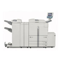
Canon iR105 Series Function Manual (167 pages)
Remote UI Guide
Brand:
Canon
| Category:
Copier
| Size: 6.08 MB
Table of Contents
Manuals for the Machine
4
Table of Contents
7
Preface
9
How to Use this Manual
9
Symbols Used in this Manual
9
Keys and Buttons Used in this Manual
10
Displays Used in this Manual
11
Abbreviations Used in this Manual
12
Legal Notices
13
Trademarks
13
Copyright
13
Disclaimers
14
Chapter 1 Using the Remote UI
15
Machines Covered in this Manual
16
Overview of the Remote UI
17
System Requirements
23
Before You Start the Remote UI
24
Setting the Remote UI to on
25
Starting the Remote UI
29
Models Not Equipped with MEAP
29
Models Equipped with MEAP
30
Chapter 2 Remote UI Functions
35
Device Status and Information Display
36
Job Management
38
Managing Print Jobs
39
Managing Copy, Send, and Fax Jobs
45
Managing Receive Jobs
50
Managing the Ir3300/2800/2200 Fax Send and Receive Jobs
54
Managing Inboxes
60
User Inboxes
62
Printing the Document
65
Memory RX Inbox
77
Confidential Fax Inboxes
82
Printing PDF or PS Files Directly (Direct Print)
87
Printing PDF Files Directly
88
Printing PS Files Directly
92
Managing the Address Book
94
Managing the Ir Address Book
95
Operating the Address Book
96
Operating the System Reference Address
106
Managing the Ir3300/2800/2200 Address Book
109
Customizing System Settings
115
Customizing System Information
115
Restarting the Machine
120
Specifying LDAP Server Settings
124
Specifying Forwarding Settings
128
Managing Department Ids
135
Import/Export Function
141
Saving Ir Address Lists in Files
142
Loading an Address Book
145
Saving Forwarding Settings in Files (Export)
148
Loading a Forwarding Settings File (Overwrite/Import)
150
Saving Additional Functions Settings in Files (Export)
152
Loading Additional Functions Settings Files (Overwrite/Import)
154
Saving an Ir3300/2800/2200 Address Book as a File (Export)
156
Loading an Ir3300/2800/2200 Address Book from a File
158
(Overwrite/Import)
158
Loading an Ir3300/2800/2200 Address Book from a File (Overwrite/Import)
158
Device Custom Settings
160
Chapter 3 Appendix
163
Index
164
Advertisement
Related Products
Canon iR1210
Canon iR1230
Canon iR1270F
Canon iR1024A
Canon iR1024i
Canon iR1024F
Canon iR1024iF
Canon iR1020J
Canon iR1510
Canon iR1530
Canon Categories
Printer
Digital Camera
All in One Printer
Camcorder
Scanner
More Canon Manuals
Login
Sign In
OR
Sign in with Facebook
Sign in with Google
Upload manual
Upload from disk
Upload from URL