Sign In
Upload
Manuals
Brands
Canon Manuals
Copier
iR1024F
Canon iR1024F Manuals
Manuals and User Guides for Canon iR1024F. We have
3
Canon iR1024F manuals available for free PDF download: Service Manual, Portable Manual, Quick Start Manual
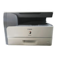
Canon iR1024F Service Manual (304 pages)
Brand:
Canon
| Category:
All in One Printer
| Size: 6 MB
Table of Contents
Table of Contents
7
Service Manual
1
Chapter 1 Introduction
17
Product Specifications
19
System Construction
21
System Configuration
21
Product Specifications
24
Names of Parts
24
External View (Front)
24
External View (Rear)
25
Cross-Section (Main Body)
26
Cross Section (ADF)
27
Using the Machine
28
Turning on the Power Switch
28
When Turning off the Main Power Switch
29
Control Panel
31
Fax Model
31
User Mode Items
32
Common Settings
32
Copy Settings
32
Tx/Rx Settings
33
Address Book Set
34
Printer Settings
35
Timer Settings
36
Adjust./Cleaning
36
Report Settings
37
System Settings
37
Maintenance by the User
39
User Maintenance Items
39
Cleaning
39
Safety
41
Safety of Toner
41
Safety of the Laser Light
41
CDRH Regulations
41
Handling the Laser Unit
41
Point to Note about Fire
43
Cautions as to the Replacement and Disposal of Lithium Battery
43
Product Specifications
44
ADF Specifications
45
Fax Specifications
45
Function List
46
Print Speed (Ir1020/1020J/1021J)
46
Print Speed (Ir1024A/F/J/N/I/If, Ir1025J/N/If)
47
Types of Paper
47
Chapter 2 Installation
51
Unpacking and Installation
53
Unpacking and Installation
55
Main Body Installation Procedure
55
Relocating the Machine
55
Installing the Card Reader
55
Points to Note
55
Checking the Contents
55
Installation Procedure
56
Registering the Card Ids
60
Chapter 3 Basic Operation
63
Construction
67
Functional Construction
67
Functional Block Diagram
68
Image Processor PCB
68
DC Controller PCB
69
Analog Processor PCB
70
Power Supply PCB
70
Relay PCB
70
Control Panel PCB
70
NCU PCB (if Equipped with Fax Functions)
70
Network PCB (if Equipped with Network Functions)
70
Modular Jack PCB (if Equipped with Fax Functions)
70
Modem PCB (if Equipped with Fax Functions)
70
Basic Sequence
72
Chapter 4 Original Exposure System
75
Table of Contents
77
Construction
79
Specifications, Control Methods, and Functions
79
Major Components
79
Basic Sequence
81
Basic Sequence at Power-On
81
Basic Sequence after Depression of Start Key (Book Mode, One Sheet of Original)
81
Basic Sequence after Depression of Start Key (ADF Mode, One Sheet of Original)
82
Various Control
82
Enlargement/Reduction
82
Magnification Change in Vertical Scan Direction
82
Magnification Change in Horizontal Scan Direction
82
Dirt Sensor Control
83
Outline
83
Parts Replacement Procedure
85
Copyboard Glass
85
Removing the Copyboard Glass
85
Procedure after Replacing the Copyboard Glass (Equipped with SEND Functions)
85
Reader Controller PCB
85
Removing the Analog Processor PCB
85
Scanner Motor
85
Removing the Reader Motor
85
Contact Sensor
86
Removing the Contact Image Sensor
86
Procedure after Replacing the CS
86
Contact Sensor HP Sensor
86
Removing the Contact Sensor Home Position Sensor
86
Chapter 5 Laser Exposure
87
Construction/Parts Replacement Procedure
89
Construction
91
Specifications and Control Mechanism
91
Main Components
92
Parts Replacement Procedure
93
Laser Scanner Unit
93
Removing the Laser Scanner Unit
93
Chapter 6 Image Formation
95
Construction
99
Specifications and Control Mechanism
99
Outline
100
Image Formation Process
101
Reproduction Processes
101
Parts Replacement Procedure
102
Developing Assembly
102
Removing the Developing Unit
102
Transfer Charging Roller
102
Removing the Transfer Charging Roller
102
Waste Toner Full Sensor
102
Removing the Waste Toner Full Sensor
102
Chapter 7 Pickup/Feeding System
103
Table of Contents
105
Construction
107
Outline
107
Detecting Jams
108
Jam Detection Outline
108
Outline
108
Types of Jams
108
Cassette Pick-Up Unit
110
Outline
110
Retry Pickup
110
Detecting the Size of Paper
110
Manual Feed Pickup Unit
111
Outline
111
Retry Pickup
111
Detecting the Size of Paper
111
Duplex Feeding Unit
112
Outline
112
Parts Replacement Procedure
113
Pickup Roller
113
Removing the Cassette Pickup Roller
113
Cassette Paper Sensor
113
Removing the Cassette Paper Sensor
113
Cassette Pickup Solenoid
113
Removing the Cassette Pickup Solenoid
113
Manual Pickup Roller
114
Removing the Manual Pickup Roller
114
Manual Feed Tray Paper Sensor
114
Removing the Manual Tray Sensor
114
Manual Feed Pickup Solenoid
114
Removing the Manual Pickup Solenoid
114
Manual Separation Pad
114
Removing the Manual Separation Pad
114
Registration Roller
115
Removing the Registration Roller
115
Registration Sensor
117
Removing the Registration Sensor
117
Registration Clutch
118
Removing the Registration Clutch
118
Feeding Roller
118
Removing the Cassete Feed Roller
118
Duplex Pickup Solenoid
118
Removing the Duplex Pickup Solenoid
118
Separation Roller
118
Removing the Cassette Separation Roller
118
Chapter 8 Fixing System
121
Table of Contents
123
Construction
125
Specifications, Control Mechanisms, and Functions
125
Outline
125
Various Control Mechanisms
127
Controlling the Fixing Film Temperature
127
Outline
127
Target Temperatures by Mode
127
Protective Functions
128
Outline
128
Failure Detection
129
Parts Replacement Procedure
130
Fixing Unit
130
Removing the Fixing Unit
130
Installing the Fixing Unit
131
Pressure Roller
132
Removing the Pressure Roller
132
Fixing Film
133
Removing the Fixing Film Unit
133
Fixing Delivery Sensor
134
Removing the Delivery Sensor
134
Chapter 9 External and Controls
135
Table of Contents
137
Control Panel
139
Outline
139
Fans
139
Power Supply System
140
Power Supply
140
Outline
140
Rated Output of the Power Supply PCB
140
Protection Function
141
Protective Functions
141
Parts Replacement Procedure
142
External Covers
142
Detaching the Right Cover
144
Drive Unit
145
Removing the Main Drive Unit
145
Detaching the
145
Removing the Pickup Drive Unit
146
Removing the Fixing/Duplex Drive Unit
146
Power Supply Unit
146
Removing the Power Supply PCB
146
Control Panel
146
Removing the Operation Panel Unit
146
Image Processor PCB
147
Removing the Image Processor PCB
147
Procedure after Replacing the Image Processor PCB
148
Ncu Pcb
148
Removing the NCU PCB
148
Modular Jack PCB
148
Removing the Modular Jack PCB
148
Modem PCB
148
Removing the Modem PCB
148
Network PCB
149
Removing the Network PCB
149
Relay PCB
149
Removing the Relay PCB
149
Interlock Switch
149
Removing the Interlock Switch
149
Fans
149
Removing the Heat Discharge Fan
149
Other
150
Removing the Speaker
150
Chapter 10 Original Feeding System
151
Table of Contents
153
Basic Construcion
155
Outline
155
Drive Mechanism
155
Basic Operation
157
Outline of Operation Mode
157
Document Size Detection
159
Paper Pickup Operation
159
Reversal Operation
159
Delivery Operation
160
Detection Jams
162
Outline
162
Parts Replacement Procedure
163
Adf
163
Removing the ADF
163
External Covers
163
Removing the
163
Removing the Rear Cover
163
Detaching the Open/Close Cover
163
ADF Drive Unit
164
Removing the Drive Unit
164
Feed Frame Unit
164
Removing the Feed Frame Unit
164
Removing the Pickup Tray
164
ADF Motor Unit
165
Removing the ADF Motor
165
Pick-Up/Feed Roller Unit
165
Removing the Pickup/Feed Roller Unit
165
Pickup Roller
166
Removing the Pickup Roller
166
Original Separation Pad
166
Removing the Separation Pad
166
Feed Roller
167
Removing the Feed Roller
167
Original Sensor
167
Removing the Document Set Sensor
167
Separation Rear Sensor
167
Removing the Separation Rear Sensor
167
Registration Sensor
167
Removing the Registration Sensor
167
Document Edge Sensor
167
Removing the Document Edge Sensor
167
Pick-Up Solenoid
168
Removing the Pickup Solenoid
168
Registaration Solenoid
168
Removing the Registration Solenoid
168
Roller Release Solenoid
168
Removing the Roller Release Solenoid
168
Chapter 11 E-Maintenance/Imageware Remote
171
E-Maintenance/Imageware Remote
171
Overview
175
Application Operation Mode
175
Communication Test
175
Communication Log
175
Detail of Communication Log
175
Initialization of E-RDS
175
SOAP Communication Function
176
Retransmission at the Time of SOAP Transmission Error
177
E-RDS Setting Screen
177
Report Output of Communication Error Log
178
Sleep Operation
178
Alarm Filtering, Alert Filtering
179
CA Certificate
179
Settings of Network Connection (Installation/Maintenance)
179
Settings of E-RDS (Installation/Maintenance)
179
Troubleshooting
180
Error Message List
180
Periodically Replaced Parts
187
Chapter 12 Maintenance and Inspection
189
Durables and Consumables
189
Periodically Replaced Parts
189
Scheduled Servicing Basic Procedure
189
Table of Contents
193
Image Adjustments
195
Image Parallelism Adjustment
195
Electrical Components
196
Procedure after Replacing the Image Processor PCB
196
Actions to Take before All Clearing (Backing up the User Data)
196
Scanning System
196
Procedure after Replacing the CIS
196
Procedure after Replacing the Copyboard Glass (if Equipped with SEND Functions)
196
Adf
198
Outline
198
Preparing a Test Sheet for Adjustment
198
Adjusting the Mechanical System
198
Adjusting the Perpendicularity
198
Adjusting the Ellectrical System
198
Adjusting the Magnification
198
Adjusting the Horizontal Registration
199
Leading Edge Registration Adjustment
199
Making Initial Checks/Outline of Electrical Components
203
Making Initial Checks
205
Site Environment
205
Checking the Paper
205
Checking the Placement of Paper
205
Checking the Durables
205
Checking the Units and Functional Systems
205
Others
206
Outline of Electrical Components
207
Clutch/Solenoid
207
List of Clutches/Solenoids/Motors/Fans
207
Sensor
209
List of Sensors
209
Pcbs
210
Lamps, Heaters, and Others
211
List of Lamps, Heaters, and Others
211
Pcbs
212
List of Pcbs
212
Table of Contents
217
Error Code Details
219
Jam Code
220
Jam Codes (Main Body)
220
Jam Codes (ADF)
221
FAX Error Codes
221
Outline
221
Error Code Outline
221
User Error Code
222
Service Error Code
222
Table of Contents
227
RTN Transmission Condition (1)><003: RTN Transmission Condition (2)><004: RTN Transmission
228
Outline
231
Chapter 15 Self Diagnosis
233
Chapter 16 Service Mode
233
Default Settings
233
Service Error Code
240
Outline
240
Setting of Bit Switch (SSSW)
240
Bit Switch Composition
240
Sssw-Sw01
240
List of Functions
240
Detailed Discussions of Bit 0
240
Sssw-Sw03
240
Detailed Discussions of Bit 7
241
Detailed Discussions of Bit 7
242
Sssw-Sw13
243
List of Functions
244
Detailed Discussions of Bit 2
244
Detailed Discussions of Bit 6
244
Detailed Discussions of Bit 7
244
Sssw-Sw14
244
List of Functions
245
Detailed Discussions of Bit 1
245
Detailed Discussions of Bit 2
245
Setting of Menu Switch (Menu)
246
Menu Switch Composition
246
No.005 NL Equalizer
246
No.006 Telephone Line Monitor
246
No.007 ATT Transmission Level
246
No.008 V.34 Modulation Speed Upper Limit
246
No.009 V.34 Data Speed Upper Limit
246
Detailed Discussions of Bit 0
246
002: RTN Transmission Condition (1)><003: RTN Transmission Condition (2)><004: RTN Transmission Condition (3)
247
No.010 Frequency of the Pseudo CI Signal>
247
005: NCC Pause Length (Pre-ID Code)
248
006: NCC Pause Length (Post-ID Code)
248
010: Line Connection Identification Length
248
011: T.30 T1 Timer (for Reception)
248
013: T.30 EOL Timer
248
015: Hooking Detection Time
248
016: Time Length to First Response at Time of Fax/Tel Switchover
248
017: Pseudo RBT Signal Pattern on Time Length><018: Pseudo RBT Signal Pattern off Time Length (Short)><019: Pseudo RBT Signal Pattern off Time Length (Long)
248
020: Pseudo CI Signal Pattern on Time Length><021: Pseudo CI Signal Pattern off Time Length (Short)><022: Pseudo CI Signal Pattern off Time Length (Long)
248
023: CNG Detention Level for Fax/Tel Switchover
248
Setting of Scanner Functions (SCANNER)
252
Numeric Parameter Functional Configuration
252
024:CIS Scan Position During ADF Scanning
253
026:Distance from the Standby Position of CIS to the Shading Start Point
253
031: Vertical Scan Start Position Adjustment
253
032: Horizontal Scan Start Position Adjustment
253
033: Vertical Scan Magnification Correction
253
034: Horizontal Scan Magnification Correction
253
035: - 036:Reader Motor Speed Change
253
041: Vertical Scan Start Position Adjustment (When Scanning on a Document Fed from ADF)
253
042: Horizontal Scan Start Position Adjustment (When Scanning on a Document Fed from ADF)
253
043: Horizontal Scan End Position Correction ((Copy:scanning on ADF)
253
045: Horizontal Scan End Position Correction (Fine:scanning on ADF)
254
046: Horizontal Scan End Position Correction (Standard:scanning on ADF)
254
047: Vertical Scan Magnification Correction (When Scanning on a Document Fed from ADF)
254
048: Horizontal Scan Magnification Correction (When Scanning on a Document Fed from ADF)
254
054: Pickup Motor Speed Correction (When the ADF Is Used)
254
193: ADF Special Standard-Sized Paper: LGL Misidentification-Ready
254
194: ADF Special Standard-Sized Paper: LTR Misidentification-Ready
254
195: ADF Special Standard-Sized Paper: LTR_R Misidentification-Ready
254
213: XYZ Correction Value (X) of Standard White Plate> (Equipped with SEND Functions)
254
214: XYZ Correction Value (Y) of Standard White Plate> (Equipped with SEND Functions)
255
215: XYZ Correction Value (Z) of Standard White Plate> (Equipped with SEND Functions)
255
Setting of Printer Functions (PRINTER)
255
Service Soft Switch Settings (PRINTER)
255
Sssw-Sw05
255
List of Functions
255
Detailed Discussions of Bit 0
255
Sssw-Sw14
256
Numerin Parameter Settings (Numeric Prama.)
257
Numeric Parameter Functional Configuration
257
031: Top Registration Adjustment (Manual Feed Tray)
257
032: Top Registration Adjustment (Cassette)
257
033: Top Registration Adjustment (Duplex Unit)
258
034: Left-End Registration Adjustment (Manual Feed Tray)
258
035: Left-End Registration Adjustment (Cassette 1)
258
036: Left-End Registration Adjustment (Cassette 2)
258
039: Left-End Registration Adjustment (Duplex Unit)
258
040: Target Fixing Temperature Adjustment (Manual Feed Tray)
258
041: Target Fixing Temperature Adjustment (Cassette 1)
258
042: Target Fixing Temperature Adjustment (Cassette 2)
258
051: Target 2-Sided Temperature Adjustment
258
053: Margin Adjustment at the Leading Edge of the Copy
258
Network Parameter Settings (NETWORK)
259
Confirmation of Contents of CA Certificate
259
Setting of System Functions (SYSTEM)
259
Bit Switch Settings
259
Registration of Accessories (ACC)
259
Accessory Registration
259
Erds Parameter Settings (E-RDS)
260
Settings Related to E-RDS
260
Display of Counter Information (COUNTER)
260
Counters
260
Clearing Counters
261
Service Report (REPORT)
262
Report Output
262
System Data List
262
System Dump List
262
Counter List
264
Error Log List
264
Spec List
266
Service Label
267
E-RDS Communication Error Log List
267
Download (DOWNLOAD)
268
Download
268
Initialization of Set Value (CLEAR)
268
Clear
268
Error Display (ERROR DISPLAY)
268
Error Display
268
Display of ROM Information (ROM)
269
ROM Display
269
Test Mode (TEST)
270
MODEM Test ((4) MODEM TEST)
271
Function Test <(6) Function Test
273
Roller Cleaning Mode ((0) ROLLER CLEAN)
277
Table of Contents
281
Making Preparations
283
Registering the System Software
283
Connection
285
Outline
283
Overview of Upgrade
283
Overview of Service Support Tool
283
Downloading System Software
286
Downloading System
286
Downloading Procedure
286
Downloading BOOT
286
Other Upgrade Methods
291
Downloading the PCL Software
291
Downloading the CA Certificate
291
Chapter 17 Upgrading
297
Chapter 18 Service Tools
297
Service Tools
297
Special Tools
299
Service Tools
301
Advertisement
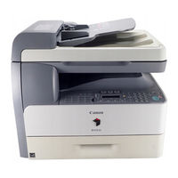
Canon iR1024F Portable Manual (96 pages)
Brand:
Canon
| Category:
Printer
| Size: 3 MB
Table of Contents
Symbols Used
4
Symbol Description
4
Table of Contents
7
Chapter 1 Maintenance and Inspection
13
Periodically Replaced Parts
13
Durables and Consumables
13
1Durables
13
Scheduled Servicing Basic Procedure
13
1Periodeical Service Items
13
Chapter 2 Standards and Adjustments
15
Image Adjustments
15
1Image Parallelism Adjustment
15
Scanning System
16
1Procedure after Replacing the CIS
16
2Procedure after Replacing the Copyboard Glass (if Equipped with SEND Functions)
16
Electrical Components
16
1Procedure after Replacing the Image Processor PCB
16
2Actions to Take before All Clearing (Backing up the User Data)
16
Chapter 3 Error Code
19
Error Code Details
19
Jam Code
20
1Jam Codes (Main Body)
20
2Jam Codes (ADF)
21
Chapter 4 User Mode Items
23
User Mode Items
23
1Common Settings
23
2Copy Settings
23
3Tx/Rx Settings
24
4Address Book Set
25
5Printer Settings
26
6Timer Settings
27
7Adjust./Cleaning
27
8Report Settings
28
9System Settings
28
Chapter 5 Service Mode
31
Fax System Service Mode
31
Service Soft Switch Settings (SSSW)
31
Outline
31
Sssw-Sw01
31
List of Functions
31
Sssw-Sw03
31
Sssw-Sw04
32
Sssw-Sw05
33
Sssw-Sw12
33
Sssw-Sw13
34
Sssw-Sw14
35
Sssw-Sw28
35
Sssw-Sw30
36
Sssw-Sw34
36
Menu Switch Settings (MENU)
37
Menu Switch Composition
37
005 NL Equalizer
37
006 Telephone Line Monitor
37
007 ATT Transmission Level
37
008 V.34 Modulation Speed Upper Limit
38
009 V.34 Data Speed Upper Limit
38
010 Frequency of the Pseudo CI Signal
38
Numeric Parameter Settings (NUMERIC Param.)
38
Numerical Parameter Composition
38
002: RTN Transmission Condition (1)><003: RTN Transmission Condition (2)><004: RTN Transmission Condition (3)
39
005: NCC Pause Length (Pre-ID Code)
39
006: NCC Pause Length (Post-ID Code)
39
010: Line Connection Identification Length
39
011: T.30 T1 Timer (for Reception)
39
013: T.30 EOL Timer
39
015: Hooking Detection Time
39
016: Time Length to First Response at Time of Fax/Tel Switchover
39
017: Pseudo RBT Signal Pattern on Time Length><018: Pseudo RBT Signal Pattern off Time Length (Short)><019: Pseudo RBT Signal Pattern off Time Length (Long)
39
020: Pseudo CI Signal Pattern on Time Length><021: Pseudo CI Signal Pattern off Time Length (Short)><022: Pseudo CI Signal Pattern off Time Length (Long)
39
023: CNG Detention Level for Fax/Tel Switchover
40
024: Pseudo RBT Transmission Level at Time of Fax/Tel Switchover
40
025: Answering Machine Connection Function Signal Detection Time
40
027: V.21 Low-Speed Flag Preamble Identification Length
40
056 - 061: Count Type Select
40
Scanner Function Settings (SCANNER)
43
Numeric Parameter Functional Configuration
43
024:CIS Scan Position During ADF Scanning
44
026:Distance from the Standby Position of CIS to the Shading Start Point
44
031: Vertical Scan Start Position Adjustment
44
032: Horizontal Scan Start Position Adjustment
44
033: Vertical Scan Magnification Correction
44
034: Horizontal Scan Magnification Correction
44
035: - 036:Reader Motor Speed Change
44
041: Vertical Scan Start Position Adjustment (When Scanning on a Document Fed from ADF)
45
042: Horizontal Scan Start Position Adjustment (When Scanning on a Document Fed from ADF)
45
043: Horizontal Scan End Position Correction ((Copy:scanning on ADF)
45
044: Horizontal Scan End Position Correction (Superfine:scanning on ADF)
45
045: Horizontal Scan End Position Correction (Fine:scanning on ADF)
45
046: Horizontal Scan End Position Correction (Standard:scanning on ADF)
45
047: Vertical Scan Magnification Correction (When Scanning on a Document Fed from ADF)
45
048: Horizontal Scan Magnification Correction (When Scanning on a Document Fed from ADF)
45
054: Pickup Motor Speed Correction (When the ADF Is Used)
45
193: ADF Special Standard-Sized Paper: LGL Misidentification-Ready
45
195: ADF Special Standard-Sized Paper: LTR_R Misidentification-Ready
46
213: XYZ Correction Value (X) of Standard White Plate> (Equipped with SEND Functions)
46
214: XYZ Correction Value (Y) of Standard White Plate> (Equipped with SEND Functions)
46
215: XYZ Correction Value (Z) of Standard White Plate> (Equipped with SEND Functions)
46
Printer Function Settings (PRINTER)
46
Service Soft Switch Settings
46
List of Function
48
Numeric Parameter Settings (NUMERIC Param.)
48
Network Parameter Settings (NETWORK)
51
Confirmation of Contents of CA Certificate
51
Setting of System Functions (SYSTEM)
51
Bit Switch Settings
51
Registration of Accessories (ACC)
51
Accessory Registration
51
Erds Parameter Settings (E-RDS)
51
Settings Related to E-RDS
51
Display of Counter Information (COUNTER)
52
Counters
52
Clearing Counters
53
Report Output (REPORT)
54
Report Output
54
Service Data List
54
System Data List
54
System Dump List
54
Counter List
56
Error Log List
56
Spec List
58
Service Label
59
E-RDS Communication Error Log List
59
Download (DOWNLOAD)
60
Download
60
Data Initialization Mode (CLEAR)
60
Clear
60
Error Display (ERROR DISPLAY)
60
Error Display
60
Display of ROM Information (ROM)
60
ROM Display
60
Test Mode (TEST MODE)
62
D-RAM Test<(1) D-RAM TEST
62
Scan Test ((2) SCAN TEST)
62
Print Test ((3) PRINT TEST)
62
MODEM Test ((4) MODEM TEST)
63
Function Test <(6) Function Test
65
Roller Cleaning Mode ((0) ROLLER CLEAN)
69
Chapter 6 Outline of Components
71
Clutch/Solenoid
71
1List of Clutches/Solenoids/Motors/Fans
71
Sensor
73
1List of Sensors
73
Lamps, Heaters, and Others
75
1List of Lamps, Heaters, and Others
75
Pcbs
76
1List of Pcbs
76
System Construction
79
1Functional Construction
79
2Functional Block Diagram
80
3Image Processor PCB
80
4DC Controller PCB
81
5Analog Processor PCB
82
6Power Supply PCB
82
7Relay PCB
82
8Control Panel PCB
82
9NCU PCB (if Equipped with Fax Functions)
82
10Network PCB (if Equipped with Network Functions)
82
11Modular Jack PCB (if Equipped with Fax Functions)
82
12Modem PCB (if Equipped with Fax Functions)
82
System Construction
84
1System Configuration
84
Product Specifications
87
2ADF Specifications
88
3Fax Specifications
88
Function List
89
1Print Speed (Ir1020/1020J/1021J)
89
2Print Speed (Ir1024A/F/J/N/I/If, Ir1025J/N/If)
90
3Types of Paper
90
Upgrading
93
Chapter 8 Upgrading
93
Overview of Upgrade
93
Canon iR1024F Quick Start Manual (62 pages)
Brand:
Canon
| Category:
Copier
| Size: 3 MB
Table of Contents
Set up the Machine
2
Do You Have Everything
2
Manuals for the Machine
3
Install the Toner Cartridge
4
Load Paper
8
Set the Date and Time
12
Guidelines for Entering Information
14
Set the Telephone Line Type
18
Select the Receive Mode that Suits Your Needs
20
Specify the IP Address Settings
22
Installing/Uninstalling Software
26
Installation Procedure
26
Usb Connection
27
Uninstallation Procedure
32
Using Help
34
Online Help
34
Context-Sensitive Help
35
Sending Documents
36
Specify the Destination
37
Start Copying
39
Select the Printer
40
Start Scanning
43
Prepare the Network
46
Operate the Machine
47
Toner Cartridge
48
Drum Unit
50
Clearing Jams
52
Document Jams
52
Paper Jams
54
Collate Copying
60
On 1 Combination
60
Advertisement
Advertisement
Related Products
Canon iR1210
Canon iR1230
Canon iR1270F
Canon iR105 Series
Canon iR1024A
Canon iR1024i
Canon iR1024iF
Canon iR1020J
Canon iR1510
Canon iR1530
Canon Categories
Printer
Digital Camera
All in One Printer
Camcorder
Scanner
More Canon Manuals
Login
Sign In
OR
Sign in with Facebook
Sign in with Google
Upload manual
Upload from disk
Upload from URL