Allied Telesis PWR300 Layer 3 Switch Manuals
Manuals and User Guides for Allied Telesis PWR300 Layer 3 Switch. We have 4 Allied Telesis PWR300 Layer 3 Switch manuals available for free PDF download: Installation Manual
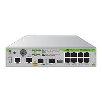
Allied Telesis PWR300 Installation Manual (158 pages)
Gigabit Layer 3+ Ethernet Switches with External Power Supply Unit(s)
Brand: Allied Telesis
|
Category: Switch
|
Size: 11 MB
Table of Contents
-
Preface
15 -
-
Front Panel20
-
Features21
-
Ports 1 to 823
-
USB Port32
-
Console Port33
-
-
-
Front Panel40
-
Features41
-
Ports 1 to 841
-
Port 1141
-
Poe Budgets41
-
USB Port42
-
-
Ports 1 to 843
-
USB Port53
-
Console Port54
-
-
-
-
-
-
-
-
-
-
-
Gs980Em/10H135
-
Gs980Em/11Pt135
-
-
-
-
-
Port 11 Poe-IN142
-
-
SFP Ports145
-
-
Certifications154
Advertisement

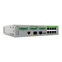
Allied Telesis PWR300 Installation Manual (124 pages)
Gigabit Layer 3+ Ethernet Switches with External Power Supply Unit
Brand: Allied Telesis
|
Category: Switch
|
Size: 7 MB
Table of Contents
-
Preface
13 -
-
Front Panel18
-
Features19
-
Ports 1 to 821
-
USB Port30
-
Console Port31
-
-
-
-
-
-
-
-
-
-
X320-10GH105
-
-
-
-
X320-10GH Switch108
-
SFP Ports113
-
-
-
Certifications120
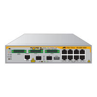
Allied Telesis PWR300 Installation Manual (124 pages)
Gigabit Layer 3+ Ethernet Switches with External Power Supply Unit
Brand: Allied Telesis
|
Category: Switch
|
Size: 5 MB
Table of Contents
-
Preface13
-
-
Front Panel18
-
Features19
-
Ports 1 to 819
-
Poe+ Budgets19
-
USB Port20
-
Ports 1 to 821
-
Leds29
-
USB Port30
-
USB Port LED30
-
Console Port31
-
Switch Leds32
-
-
-
-
-
-
-
-
Gs980Em/10H105
-
-
SFP Ports113
-
-
Certifications120
Advertisement
Allied Telesis PWR300 Installation Manual (158 pages)
Gigabit Layer 3+ Ethernet Switches with External Power Supply Unit(s)
Brand: Allied Telesis
|
Category: Switch
|
Size: 8 MB
Advertisement
Related Products
- Allied Telesis PWR600
- Allied Telesis Patch 89262-08
- Allied Telesis AlliedWare Plus AT-XEM2-12XT
- Allied Telesis AlliedWare Plus AT-PWR600
- Allied Telesis AlliedWare Plus AT-x530-52GPXm
- Allied Telesis AlliedWare Plus AT-x950-52XTQm
- Allied Telesis AlliedWare Plus AT-PWR600R-80 DC
- Allied Telesis AlliedWare Plus SE540L Series
- Allied Telesis AlliedWare Plus x540L-28XTm
- Allied Telesis AlliedWare Plus SE540L-28XTm