Table of Contents
Advertisement
Quick Links
Advertisement
Table of Contents

Related Manuals for Allied Telesis GS980EM/11PT


Summary of Contents for Allied Telesis GS980EM/11PT
- Page 1 GS980EM Series Gigabit Layer 3+ Ethernet Switches with External Power Supply Unit(s) AlliedWare Plus™ v5.5.0 GS980EM/11PT GS980EM/10H PWR300 AT-GS980EM-11PT POE-OUT POE-OUT POE-IN POE-IN 4833 Installation Guide 613-002818 Rev. C...
- Page 2 Allied Telesis, Inc. has been advised of, known, or should have known, the...
- Page 3 Electrical Safety and Emissions Standards This section contains the following: “US Federal Communications Commission” “Industry Canada” “Regulatory Approvals” on page 4 “Translated Safety Statements” on page 5 US Federal Communications Commission Radiated Energy Note This equipment has been tested and found to comply with the limits for a Class A digital device pursuant to Part 15 of FCC Rules.
- Page 4 EN61000-4-5 EN61000-4-6 EN61000-4-8 EN61000-4-11 2014/30/EC EMC Directive 2014/35/EC Low Voltage Directive Allied Telesis approved SFP modules EN60825-1 EN60825-2 UL/IEC/EN60950-1 FDA CDRH accession registration Warning: In a domestic environment this product may cause radio interference in which case the user may be required to take adequate measures.
- Page 5 Translated Safety Statements Important: Safety statements that have the symbol are translated into multiple languages in the Translated Safety Statements document, which is available at www.alliedtelesis.com/library. Remarque: Les consignes de sécurité portant le symbole sont traduites dans plusieurs langues dans le document Translated Safety Statements, disponible à...
-
Page 7: Table Of Contents
Console Port.................................33 Fault and Power LEDs ..............................34 Switch LEDs ................................34 eco-friendly Command ..............................35 Planning the Installation ...............................36 Chapter 2: Overview of the GS980EM/11PT Switch ......................39 Front Panel ...................................40 Features ..................................41 Ports 1 to 8 ................................41 Port 11...................................41 PoE Budgets .................................41 Ports 9 and 10 ...............................41... - Page 8 PWR300 Power Supply ............................71 Accessory Kits ................................72 GS980EM/10H Switch Accessory Kit ........................72 GS980EM/11PT Switch Accessory Kit ......................... 73 19-Inch Rack Mount Kit ............................74 PWR300 Power Supply Accessory Kit ......................... 75 RKMT-J24 Wall Mount Kit ............................ 76 DRMT-J03 DIN Rail Mount Kit..........................
- Page 9 GS980EM Series Installation Guide Powering on the PWR300 Power Supply......................125 Powering on the GS980EM/11PT Switch........................128 Connecting Port 11 to a PoE Power Source .......................128 Connecting the PWR90ADP Power Adapter.......................129 Powering on the PWR90ADP AC/DC Adapter....................130 Monitoring the Initialization Processes ........................132 Starting a Local Management Session........................133...
- Page 10 Contents...
- Page 11 Figure 6: Fault and Power LEDs............................34 Figure 7: Front Panel of the GS980EM/11PT Switch ......................40 Figure 8: LEDs for Ports 1 to 8 on the GS980EM/11PT Switch...................44 Figure 9: LEDs for Port 11 on the GS980EM/11PT Switch ....................48 Figure 10: PWR90ADP AC/DC Power Adapter........................50 Figure 11: SFP Transceiver Ports LEDs..........................52...
- Page 12 Figure 66: Lowering the Power Cord Retaining Clip......................127 Figure 67: Connecting the Power Cord to an AC Power Source ..................127 Figure 68: Connecting the PWR90ADP Power Adapter to the GS980EM/11PT Switch ............129 Figure 69: Connecting the Power Cord to the Power Adapter....................129 Figure 70: Connecting the Power Cord to the Power Adapter....................131...
- Page 13 Table 15: LEDs for Ports 1 to 8 on the GS980EM/11PT Switch ..................45 Table 16: PoE Budget from Port 11 for Ports 1 to 8 on the GS980EM/11PT Switch ............47 Table 17: LEDs for Port 11 on the GS980EM/11PT Switch ....................48 Table 18: LEDS for the SFP Transceiver Ports ........................52...
- Page 14 Tables...
-
Page 15: Preface
This guide contains the hardware installation instructions for the GS980EM Series Gigabit L3 PoE++ Switches and the PWR300 power supply unit. The preface contains the following sections: “Safety Symbols Used in this Document” on page 16 “Contacting Allied Telesis” on page 17 ... -
Page 16: Safety Symbols Used In This Document
Preface Safety Symbols Used in this Document This document uses the following conventions. Note Notes provide additional information. Caution Cautions inform you that performing or omitting a specific action may result in equipment damage or loss of data. Warning Warnings inform you that performing or omitting a specific action may result in bodily injury. -
Page 17: Contacting Allied Telesis
GS980EM Series Installation Guide Contacting Allied Telesis If you need assistance with this product, you may contact Allied Telesis technical support by going to the Support & Services section of the Allied Telesis web site at www.alliedtelesis.com/support. You can find links for the following services on this page: 24/7 Online Support —... - Page 18 Preface...
- Page 19 Chapter 1 GS980EM/10H Overview of the Switch This chapter describes the hardware features of the GS980EM/10H Switch. The sections in the chapter are listed here: “Front Panel” on page 20 “Features” on page 21 “Ports 1 to 8” on page 23 ...
-
Page 20: Chapter 1: Overview Of The Gs980Em/10H Switch
Chapter 1: Overview of the GS980EM/10H Switch Front Panel The front panel of the GS980EM/10H Switch is shown in Figure 1. GS980EM/10H 3 PWR300 Connectors FAULT Console 8 10/100/1000Mbps 2 SFP 1000Mbps Port Transceiver Ports Twisted Pair Ports PoE++ w/LEDs USB Port Figure 1. -
Page 21: Features
GS980EM Series Installation Guide Features Here are the basic hardware features of the GS980EM/10H Switch. Ports 1 to 8 Basic features of ports 1 to 8 are listed here: 10/100/1000Mbps PoE++ 90W maximum per port Powered device Classes 0 to 8 ... -
Page 22: Installation Options
Chapter 1: Overview of the GS980EM/10H Switch Installation Installation options are listed here: Options Table or desktop Standard 19-inch equipment rack Wall DIN rail Management Here are the methods for managing the switch: Methods Local management through the Console Port ... -
Page 23: Ports 1 To 8
GS980EM Series Installation Guide Ports 1 to 8 The following sections describe twisted pair ports 1 to 8 on the GS980EM/ 10H Switch. Specifications The basic specifications are listed in Table 2. Table 2. Specifications for Ports 1 to 8 on the GS980EM/10H Switch Specification Description Port Speed... -
Page 24: Powered Device Classes
Chapter 1: Overview of the GS980EM/10H Switch Powered Device Ports 1 to 8 support the powered device classes listed in Table 3. Classes Table 3. Supported Powered Device Classes on Ports 1 to 8 of the GS980EM/10H Switch Maximum Power at Maximum Power at Class Switch Port... -
Page 25: Table 4: Leds For Ports 1 To 8 On The Gs980Em/10H Switch
GS980EM Series Installation Guide Table 4. LEDs for Ports 1 to 8 on the GS980EM/10H Switch State Description Solid Green A port has established a 1000Mbps link to a network device. Flashing A port is transmitting or receiving data at Green 1000Mbps. -
Page 26: Cable Requirements
Chapter 1: Overview of the GS980EM/10H Switch Cable The minimum cable requirements for the ports 1 to 8 are listed here. Requirements 10Mbps or 100Mbps: Standard TIA/EIA 568-B-compliant Category 3 unshielded cabling. 1000Mbps: Standard TIA/EIA 568-A-compliant Category 5 or TIA/ ... -
Page 27: Pwr300 Power Supply
GS980EM Series Installation Guide PWR300 Power Supply The GS980EM/10H Switch is powered with the PWR300 power supply. Refer to Figure 3. The power supply provides both system power for the switch as well as PoE++ power on ports 1 to 8 for powered devices. DC Out/ Fault LED AC Power Supply... -
Page 28: Poe Port Priorities
Chapter 1: Overview of the GS980EM/10H Switch PoE Port Priorities If the switch determines that the power requirements of the powered devices exceed its power budget, it will deny power to some ports based on a system called port priorities. You can use this mechanism to ensure that powered devices critical to the operations of your network are given preferential treatment by the switch in the distribution of power should the demands of the devices exceed the available capacity. -
Page 29: Table 6: Denial Of Ports By Priority
GS980EM Series Installation Guide The GS980EM/10H switch does not use Dynamic Power Management (DPM). Therefore, the software cannot detect a failure of the PSU and decide which ports to deny power to. As a result, more ports may be powered than the unit can restart due to lack of power. In this case, the switch will deny Low priority ports and to attempt to repower once the CPU has determined the new power budget. - Page 30 Chapter 1: Overview of the GS980EM/10H Switch Example 1: The GS980EM/10H switch has three PWR300 units. All ports are Low priority. The total PD load is 600W. One PSU fails, leaving two PSUs. The following steps occur: 1. The switch stops providing power to all ports because they are all Low priority.
-
Page 31: Sfp Transceiver Ports
1000Mbps bi-directional (BiDi) fiber optic transceivers SFP transceivers are purchased separately. For a list of supported transceivers, refer to the product data sheet on the Allied Telesis web site. LEDs Each transceiver port has one LED. Refer to Figure 4. -
Page 32: Usb Port
Chapter 1: Overview of the GS980EM/10H Switch USB Port You can use the USB port on the management panel for the following functions: Store configuration files on flash drives. Restore configuration files to switches whose settings have been lost or corrupted. -
Page 33: Console Port
GS980EM Series Installation Guide Console Port The Console port is an RS232 serial management port. Use the port to access the AlliedWare Plus management software on the switch to configure the feature settings or monitor status or statistics. This type of management uses the management cable included with the unit. -
Page 34: Fault And Power Leds
Chapter 1: Overview of the GS980EM/10H Switch Fault and Power LEDs Switch LEDs The Fault and Power LEDs are shown in Figure 6. Fault, Power and USB LEDs Figure 6. Fault and Power LEDs Note The USB LED is described in “USB Port” on page 32. The states of the LEDs are described in Table 9. -
Page 35: Eco-Friendly Command
GS980EM Series Installation Guide eco-friendly Command The eco-friendly command is used to toggle the port LEDs on or off. You can turn off the LEDs to conserve electricity when you are not monitoring the device. You can toggle the LEDs with the ECOFRIENDLY LED and NO ECOFRIENDLY LED commands in the Global Configuration mode of the command line interface of the AlliedWare Plus management software. -
Page 36: Planning The Installation
Chapter 1: Overview of the GS980EM/10H Switch Planning the Installation Here are questions to consider before connecting devices to ports 1 to 8: Which ports will be connected to PoE devices? Which ports will be connected to non-PoE devices? ... -
Page 37: Table 11: Worksheet Column Descriptions
GS980EM Series Installation Guide Table 10. Port 1 to 8 Worksheet for the GS980EM/10H Switch (Continued) Maximum Priority PoE Device - PoE Class Port Device/Location Watts of PoE (Low, High, Yes/No 0 to 8 Class or Critical) Total PoE Watts The columns in the table are described in Table 11. -
Page 38: Table 12: Power Worksheet For The Gs980Em/10H Switch
Chapter 1: Overview of the GS980EM/10H Switch Table 11. Worksheet Column Descriptions (Continued) Column Description Total PoE Watts Add up the numbers in the Maximum Watts of PoE Class column and enter it here. This number must be equal to or less than the PoE budget of the PWR300 power supplies connected to the switch. - Page 39 Chapter 2 GS980EM/11PT Overview of the Switch This chapter describes the hardware features of the GS980EM/11PT Switch. The sections in the chapter are listed here: “Front Panel” on page 40 “Features” on page 41 “Ports 1 to 8” on page 43 ...
-
Page 40: Chapter 2: Overview Of The Gs980Em/11Pt Switch
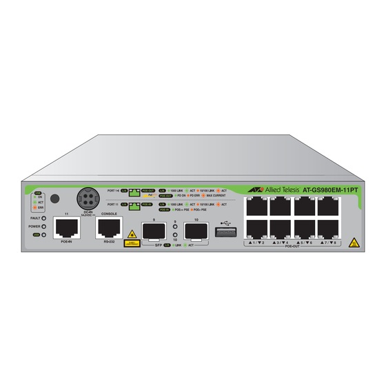
Chapter 2: Overview of the GS980EM/11PT Switch Front Panel The front panel of the GS980EM/11PT Switch is shown in Figure 7. GS980EM/11PT PWR90ADP Power Adapter Frame Ground Connector FAULT Console 2 SFP 1000M 8 10/100/1000Mbps Port Port 11 Transceiver Ports... -
Page 41: Features
GS980EM Series Installation Guide Features Here are the basic hardware features of the GS980EM/11PT Switch. Ports 1 to 8 The basic features of ports 1 to 8 are listed here: 10/100/1000Mbps PoE+ Support powered device Classes 0 to 4 ... -
Page 42: Installation Options
Chapter 2: Overview of the GS980EM/11PT Switch Installation Installation options are listed here: Options Table or desktop Standard 19-inch equipment rack Wall DIN rail Management Here are the methods for managing the switch: Methods Local management through the Console Port ... -
Page 43: Ports 1 To 8
The following sections describe twisted pair ports 1 to 8 on the GS980EM/ 11PT Switch. Specifications The basic specifications are listed in Table 13. Table 13. Specifications for Ports 1 to 8 on the GS980EM/11PT Switch Specification Description Port Speed 10/100/1000Mbps. -
Page 44: Powered Device Classes
Ports 1 to 8 LEDs Ports 1 to 8 have two LEDs. Refer to Figure 8. Speed/Activity PD Status Speed/Activity PD Status Figure 8. LEDs for Ports 1 to 8 on the GS980EM/11PT Switch. The LEDs are described in Table 15 on page 45. -
Page 45: Table 15: Leds For Ports 1 To 8 On The Gs980Em/11Pt Switch
GS980EM Series Installation Guide Table 15. LEDs for Ports 1 to 8 on the GS980EM/11PT Switch State Description Solid Green A port has established a 1000Mbps link to a network device. Flashing A port is transmitting or receiving data at Green 1000Mbps. -
Page 46: Cable Requirements
Chapter 2: Overview of the GS980EM/11PT Switch Cable The minimum cable requirements for the ports 1 to 8 are listed here. Requirements 10Mbps or 100Mbps: Standard TIA/EIA 568-B-compliant Category 3 unshielded cabling. 1000Mbps: Standard TIA/EIA 568-A-compliant Category 5 or TIA/ ... -
Page 47: Port 11 - Poe In Pass-Through
PoE budget of 46W for ports 1 to 8 will connect port 11 to a Class 8 power source. Table 16. PoE Budget from Port 11 for Ports 1 to 8 on the GS980EM/11PT Switch Power Source Class on... -
Page 48: Port 11 Leds
The LEDs for port 11 are identified in Figure 9. Speed/Activity PoE PD Figure 9. LEDs for Port 11 on the GS980EM/11PT Switch The LEDs are defined in Table 17. Table 17. LEDs for Port 11 on the GS980EM/11PT Switch... -
Page 49: Cable Requirements
GS980EM Series Installation Guide Table 17. LEDs for Port 11 on the GS980EM/11PT Switch (Continued) State Description Solid Green The port is receiving power from a IEEE803.3bt Class 8 or 6 PoE power source. The maximum power budget for powered devices on ports 1 to 8 is 46W or 30W. -
Page 50: Pwr90Adp Ac/Dc Power Adapter
Chapter 2: Overview of the GS980EM/11PT Switch PWR90ADP AC/DC Power Adapter The GS980EM/11PT Switch can be powered two ways. One way is by connecting a Class 4, 6, or 8 PoE power source to port 11. This is described in “Port 11 - PoE IN Pass-through” on page 47. The second way is with the PWR90ADP AC/DC power adapter, shown in Figure 10. -
Page 51: Poe Port Priorities
Low priority level, power is provided to the ports based on port number, in ascending order. Power allocation on the GS980EM/11PT switch is dynamic. The switch automatically ceases power transmissions on ports if its power budget is at maximum usage and new powered devices, connected to ports with higher priorities, become active. -
Page 52: Sfp Transceiver Ports
1000Mbps bi-directional (BiDi) fiber optic transceivers SFP transceivers are purchased separately. For a list of supported transceivers, refer to the product data sheet on the Allied Telesis web site. LEDs Each transceiver port has one LED. Refer to Figure 11. -
Page 53: Usb Port
Update the AlliedWare Plus management software. USB Port LED The USB port has one LED, shown in Figure 12 on the GS980EM/11PT switch. USB Port LED USB Port Figure 12. GS980EM/11PT USB Port and LED The states of the LEDs are described in Table 19. -
Page 54: Console Port
Chapter 2: Overview of the GS980EM/11PT Switch Console Port The Console port is an RS232 serial management port. Use the port to access the AlliedWare Plus management software on the switch to configure the feature settings or monitor status or statistics. This type of management uses the management cable included with the unit. -
Page 55: Fault And Power Leds
GS980EM Series Installation Guide Fault and Power LEDs The Fault and Power LEDs are shown in Figure 13. Fault, Power and USB LEDs Figure 13. Fault and Power LEDs Note The USB LED is described in “USB Port” on page 53. The states of the LEDs are described in Table 20. -
Page 56: Eco-Friendly Command
Chapter 2: Overview of the GS980EM/11PT Switch eco-friendly Command The eco-friendly command is used to toggle the port LEDs on or off. You can turn off the LEDs to conserve electricity when you are not monitoring the device. You can toggle the LEDs with the ECOFRIENDLY LED and NO ECOFRIENDLY LED commands in the Global Configuration mode of the command line interface of the AlliedWare Plus management software. -
Page 57: Switch Markings
GS980EM Series Installation Guide Switch Markings There are various labels on the bottom of the switch. If applicable, these may include: Manufacture identification Model identification Equipment rating Voltage supply Warranty seal Manufacture date Importer’s name and address ... -
Page 58: Planning The Installation
Managing the switch will be easier if you take the time to fill-out the worksheets in Table 21 and Table 23 on page 60. Table 21. Port 1 to 8 Worksheet for the GS980EM/11PT Switch Maximum Priority PoE Device -... -
Page 59: Table 22: Worksheet Column Descriptions
GS980EM Series Installation Guide Table 21. Port 1 to 8 Worksheet for the GS980EM/11PT Switch (Continued) Maximum Priority PoE Device - PoE Class Port Device/Location Watts of PoE (Low, High, Yes/No 0 to 4 Class or Critical) Total PoE Watts The columns in the table are described in Table 22. -
Page 60: Table 23: Power Worksheet For The Gs980Em/11Pt Switch
Will the switch also be powered with the PWR90ADP AC/DC adapter? Table 23 can be used as a record of how the switch is powered. Table 23. Power Worksheet for the GS980EM/11PT Switch Installed PoE Budget for Power Source... -
Page 61: Chapter 3: Beginning The Installation
Chapter 3 Beginning the Installation The chapter contains the following sections: “Reviewing Safety Precautions” on page 62 “Choosing a Site for the Device” on page 67 “Unpacking the Equipment” on page 69 “Accessory Kits” on page 72 ... -
Page 62: Reviewing Safety Precautions
Chapter 3: Beginning the Installation Reviewing Safety Precautions Please review the following safety precautions before beginning the installation procedure. Important: Safety statements that have the symbol are translated into multiple languages in the Translated Safety Statements document, which is available at www.alliedtelesis.com/library. Remarque: Les consignes de sécurité... - Page 63 GS980EM Series Installation Guide Warning Do not work on equipment or cables during periods of lightning activity. E2 Warning Class I Equipment. This equipment must be earthed. The power plug must be connected to a properly wired earth ground socket outlet.
- Page 64 Chapter 3: Beginning the Installation Caution Risk of explosion if battery is replaced by an incorrect type. Replace only with the same or equivalent type recommended by the manufacturer. Dispose of used batteries according to the manufacturer’s instructions. Attention: Le remplacement de la batterie par une batterie de type incorrect peut provoquer un danger d’explosion.
- Page 65 GS980EM Series Installation Guide Warning Reliable earthing of rack-mounted equipment should be maintained. Particular attention should be given to supply connections other than direct connections to the branch circuits (e.g., use of power strips). Warning An operational unit can be hot. Exercise caution when handling with unprotected hands.
- Page 66 Chapter 3: Beginning the Installation Warning Leaving the power supply powered on while connecting the harness to the switch could cause an electrical short that can damage the equipment. E127 ...
-
Page 67: Choosing A Site For The Device
GS980EM Series Installation Guide Choosing a Site for the Device Observe these requirements when planning the installation of the switch. If you plan to install the switch in an equipment rack, check that the rack is safely secured so that it will not tip over. Devices in a rack should be installed starting at the bottom, with the heavier devices near the bottom of the rack. - Page 68 Chapter 3: Beginning the Installation Powered devices connected to the LAN ports on the switch should be grounded to the same grounding conductor at the service entrance as the switch. LAN ports should have additional lightning protections as specified ...
-
Page 69: Unpacking The Equipment
C - Accessory kit Note You should retain the original packaging material in case you need to return the unit to Allied Telesis. See “GS980EM/10H Switch Accessory Kit” on page 72 for the contents of the accessory kit. -
Page 70: Gs980Em/11Pt Switch
C - Accessory kit Note You should retain the original packaging material in case you need to return the unit to Allied Telesis. See “GS980EM/11PT Switch Accessory Kit” on page 73 for the contents of the accessory kit. -
Page 71: Pwr300 Power Supply
C - Accessory kit Note You should retain the original packaging material in case you need to return the unit to Allied Telesis. See “PWR300 Power Supply Accessory Kit” on page 75 for the contents of the accessory kit. -
Page 72: Accessory Kits
Chapter 3: Beginning the Installation Accessory Kits GS980EM/10H Figure 17 lists the items in the accessory kit included with the GS980EM/ 10H switch. Contact your Allied Telesis sales representative for Switch Accessory assistance if any item is missing or damaged. Note The GS980EM/10H switch is powered by up to three PWR300 power supplies. -
Page 73: Gs980Em/11Pt Switch Accessory Kit
RJ-45 (8P8C) and DB-9 (D-sub 9-pin) connectors. One regional AC power cord One PWR90ADP power adapter 4784 Four rubber feet (adhesive type) One rack mount kit See “19-Inch Rack Mount Kit” on page 74 Figure 18. GS980EM/11PT Switch Accessory Kit... -
Page 74: 19-Inch Rack Mount Kit
Chapter 3: Beginning the Installation 19-Inch Rack Figure 19 lists the items in the 19-inch rack mount kit that are included with the GS980EM/10H switch and PWR300 power supply. The holes specified Mount Kit in Figure 19 depend on the size of the device you are installing. One straight bracket One long L-bracket Use these... -
Page 75: Pwr300 Power Supply Accessory Kit
GS980EM Series Installation Guide PWR300 Power Figure 20 lists the items in the Accessory Kit that are included with the PWR300 power supply for the GS980EM/10H switch. Supply Accessory Note The PWR300 power supply must be purchased separately. One regional AC power cord Power cord retaining clip DC power cord (external harness) -
Page 76: Rkmt-J24 Wall Mount Kit
Chapter 3: Beginning the Installation RKMT-J24 Wall Figure 21 lists the items in the optional wall mount kit. Mount Kit Note The Wall Mount Kit must be purchased separately. Four anchors for concrete walls: Length: 29.6mm (1.2 in.) Diameter: 6.0mm (0.2 in.) Four screws for wood or concrete walls: Length: 32mm (1.3 in.) -
Page 77: Drmt-J03 Din Rail Mount Kit
GS980EM Series Installation Guide DRMT-J03 DIN Figure 22 lists the items in the optional DRMT-J03 DIN Rail Mount Kit. Rail Mount Kit Note The DIN Rail Mount Kit must be purchased separately. Bracket DRMT-J03 Figure 22. DRMT-J03 DIN Rail Mount Kit RKMT-J15 Tray Figure 23 lists the items in the optional RKMT-J15 Tray Bracket Mount Kit. - Page 78 Chapter 3: Beginning the Installation...
-
Page 79: Chapter 4: Installing The Device On A Table Or Desktop
Chapter 4 Installing the Device on a Table or Desktop This chapter contains the following sections: “Planning the Installation” on page 80 “Installing the Switch on a Table or Desktop” on page 81 ... -
Page 80: Planning The Installation
Chapter 4: Installing the Device on a Table or Desktop Planning the Installation Figure 24 shows the minimum distances required between devices to ensure adequate cooling. Figure 24. Required Minimum Distances Between Devices for a Desk or Table Installation... -
Page 81: Installing The Switch On A Table Or Desktop
GS980EM Series Installation Guide Installing the Switch on a Table or Desktop This section contains the procedure for installing the switch on a table. Warning Switches should not be stacked on a table or desktop. They could present a physical safety hazard if you need to move or replace switches. - Page 82 Chapter 4: Installing the Device on a Table or Desktop Note The bumper feet are only to be used if you are installing the switch on a table. Do not install the bumper feet if you are installing the switch in an equipment rack or on a wall. 5.
-
Page 83: Chapter 5: Installing The Device In An Equipment Rack
Chapter 5 Installing the Device in an Equipment Rack This chapter contains the instructions for installing the device in an equipment rack. The procedures in this chapter are listed here: “Overview of Installing the Device in an Equipment Rack” on page 84 ... -
Page 84: Overview Of Installing The Device In An Equipment Rack
Chapter 5: Installing the Device in an Equipment Rack Overview of Installing the Device in an Equipment Rack You can install the device in a 19-inch equipment rack two ways. One way is with the Rack Mount Kit that comes standard with the device. It includes three connecting brackets;... -
Page 85: Figure 27: Gs980Em/10H Switch And Pwr300 Power Supplies In The Rkmt-J15 Bracket
GS980EM Series Installation Guide You can also install the device in an equipment rack with the optional RKMT-J15 bracket. The bracket lets you install two devices side-by-side. Refer to Figure 27 on page 85. Note When mounting using the RKMT-J15 Bracket, you must leave 1 rack unit (1U) of space between brackets. -
Page 86: Installing The Device In An Equipment Rack With The Rack Mount Kit Brackets
Chapter 5: Installing the Device in an Equipment Rack Installing the Device in an Equipment Rack with the Rack Mount Kit Brackets This section contains the procedure for installing the device in a standard 19-inch equipment rack, with the Rack Mount Kit brackets that are included with the device. -
Page 87: Figure 28: Bracket Holes
GS980EM Series Installation Guide GS980EM/10H Bracket Holes GS980EM/11PT Bracket Holes PWR300 Bracket Holes Figure 28. Bracket Holes The Rack Mount Kit brackets are shown in Figure 19 on page 74. You can install the device in one orientation, with the front panel flush with front of the equipment rack. -
Page 88: Installing The Device With The Brackets
Please review the installation guidelines in “Choosing a Site for the Switch” on page 42 before installing the device in an equipment rack. Caution The chassis may be heavy and awkward to lift. Allied Telesis recommends that you get assistance when mounting the chassis in an equipment rack. E28... -
Page 89: Figure 30: Attaching The Brackets To The Device
GS980EM Series Installation Guide To install the device in a 19-inch equipment rack with the brackets, perform the following procedure: 1. Place the device on a level, secure surface. 2. Attach the short L bracket to one side of the device and the long L bracket on the other side of the device using the eight M4x6 mm screws included with the unit. -
Page 90: Figure 32: Installing The Device In An Equipment Rack
Chapter 5: Installing the Device in an Equipment Rack 4. Have another person hold the device in the equipment rack at the desired location while you secure it using four standard equipment rack screws (not provided). Refer to Figure 32. Figure 32. -
Page 91: Figure 33: Device Secured In An Equipment Rack
GS980EM Series Installation Guide Figure 33 shows the device secured in an equipment rack. Figure 33. Device Secured in an Equipment Rack 5. Go to Chapter 8, “Cabling the Networking Ports” on page 117. -
Page 92: Installing The Device In An Equipment Rack With The Rkmt-J15 Bracket
Chapter 5: Installing the Device in an Equipment Rack Installing the Device in an Equipment Rack with the RKMT-J15 Bracket This section contains the procedure for installing the device in a standard 19-inch equipment rack, with the optional RKMT-J15 Bracket. Required Items The following items are required to install the device in an equipment rack with the RKMT-J15 Bracket:... -
Page 93: Figure 34: Installing The Rkmt-J15 Bracket In The Equipment Rack
GS980EM Series Installation Guide Figure 34. Installing the RKMT-J15 Bracket in the Equipment Rack 2. Loosen the two thumbscrews on the front of the bracket. Refer to Figure 35. Figure 35. Loosening the Two Thumbscrews on the Front of the RKMT- J15 Bracket... -
Page 94: Figure 36: Sliding Out The Tray Of The Rkmt-J15
Chapter 5: Installing the Device in an Equipment Rack 3. Slide out the bracket tray. Refer to Figure 36. Figure 36. Sliding Out the Tray of the RKMT-J15 4. Place the device in the left or right side of the bracket, with its front panel facing the front of the bracket. -
Page 95: Figure 38: Securing The Device To The Rkmt-J15 Bracket
GS980EM Series Installation Guide 5. Install two M4x6mm screws included with the RKMT-J15 to secure the device to the bracket. Refer to Figure 38. Figure 38. Securing the Device to the RKMT-J15 Bracket 6. To install a second device in the bracket, repeat steps 4 and 5. 7. -
Page 96: Figure 40: Tightening The Two Thumbscrews On The Rkmt-J15 Bracket
Chapter 5: Installing the Device in an Equipment Rack 8. Tighten the two thumbscrews to secure the tray to the bracket. Refer to Figure 40. Figure 40. Tightening the Two Thumbscrews on the RKMT-J15 Bracket 9. Go to Chapter 8, “Cabling the Networking Ports” on page 117. -
Page 97: Chapter 6: Installing The Device On The Drmt-J03 Din Rail
Chapter 6 Installing the Device on the DRMT-J03 DIN Rail The procedures in this chapter are listed here: “Installing the Device on the DRMT-J03 DIN Chassis Bracket” on page 98 “Installing the Device on a DIN Rail” on page 100 ... -
Page 98: Installing The Device On The Drmt-J03 Din Chassis Bracket
Chapter 6: Installing the Device on the DRMT-J03 DIN Rail Installing the Device on the DRMT-J03 DIN Chassis Bracket The DRMT-J03 DIN chassis bracket is shown in Figure 41. The bracket is compatible with DIN 35x7.5mm rails. Figure 41. DRMT-J03 DIN Chassis Bracket To install the device on the bracket: 1. -
Page 99: Figure 43: Screwing The Device To The Drmt-J03 Din Chassis Bracket
GS980EM Series Installation Guide 2. Screw the DRMT-J03 DIN chassis bracket to the device. Figure 43. Screwing the Device to the DRMT-J03 DIN Chassis Bracket... -
Page 100: Installing The Device On A Din Rail
Chapter 6: Installing the Device on the DRMT-J03 DIN Rail Installing the Device on a DIN Rail Figure 44 shows the proper orientation of the device on a DIN rail. Do not install the device horizontally or upside-down. Figure 44. Orientation of the Device on a DIN Rail To install the device on a DIN rail, perform the following procedure: 1. -
Page 101: Figure 46: Installing The Device On A Din Rail
GS980EM Series Installation Guide 2. With the spring-loaded lever in the down position, place the mounting tabs on the DIN rail as shown in Figure 46. Top edge of DIN rail Spring-loaded lever Mounting tabs Figure 46. Installing the Device on a DIN Rail 3. -
Page 102: Figure 47: Verifying The Din Rail Installation
Allied Telesis recommends installing DIN rail end clamps to the sides of the switch to prevent damage or network traffic loss from vibration or shock. End clamps are not available from Allied Telesis. 5. Go to Chapter 8, “Cabling the Networking Ports” on page 117. -
Page 103: Chapter 7: Installing The Device On A Wall
Chapter 7 Installing the Device on a Wall The procedures in this chapter are listed here: “Device Orientations on a Wall” on page 104 “Installation Guidelines” on page 105 “Plywood Base for a Wall with Wooden Studs” on page 107 ... -
Page 104: Device Orientations On A Wall
You can install the device on a wall with the front panel facing left, right, or down as shown in Figure 48 and Figure 49. Do not install the device facing Figure 48. Positioning the GS980EM/10H or GS980EM/11PT Switch on the Wall... -
Page 105: Installation Guidelines
GS980EM Series Installation Guide Installation Guidelines Here are the guidelines to installing the GS980EM/10H or GS980EM/11PT switch and PWR300 power supply on a wall: Wall installation requires the optional BRKT-J24 brackets. Install the device on a wall that has wooden studs or on a concrete ... - Page 106 Chapter 7: Installing the Device on a Wall Caution The supplied screws and anchors might not be appropriate for all walls. A qualified building contractor should determine the hardware requirements for your wall prior to installing the switch. E88...
-
Page 107: Plywood Base For A Wall With Wooden Studs
Figure 50. Device on the Wall with a Plywood Base The plywood base should be mounted to two studs in the wall. The recommended minimum dimensions of the plywood base for the GS980EM/10H or GS980EM/11PT switch and PWR300 power supply are listed here: Width: 55.9 centimeters (22 inches) ... -
Page 108: Figure 51: Steps To Installing The Device With A Plywood Base
Chapter 7: Installing the Device on a Wall Wall Studs Wall Plywood Base Step 1: Install the Step 2: Install the plywood base on device on the the wall. plywood base. Figure 51. Steps to Installing the Device with a Plywood Base... -
Page 109: Installing A Plywood Base
GS980EM Series Installation Guide Installing a Plywood Base A plywood base is recommended when installing the device on a wall that has wooden studs. Refer to “Plywood Base for a Wall with Wooden Studs” on page 107. Consult a qualified building contractor for installation instructions for the plywood base. -
Page 110: Installing The Device On A Plywood Base
1. Place the device on a table. 2. For the GS980EM/10H or GS980EM/11PT switch, install two BRKT- J24 wall brackets, one on each side of the front panel of the unit, with the eight M4x6mm screws included with the device. Refer to Figure 52 on page 111. -
Page 111: Figure 52: Installing The Wall Brackets On A Switch
GS980EM Series Installation Guide Figure 52. Installing the Wall Brackets on a Switch Figure 53. Installing the Wall Brackets on a Power Supply... -
Page 112: Figure 54: Securing The Device To The Plywood Base
Chapter 7: Installing the Device on a Wall 3. After attaching the brackets, have another person hold the device on the plywood base on the wall while you secure it with the four M4x32mm screws included with the device. Refer to Figure 54. GS980EM/10H (or GS980/11PT) PWR300... -
Page 113: Installing The Device On A Concrete Wall
To install the device on a concrete wall, perform the following procedure: 1. Place the device on a table. 2. For the GS980EM/10H or GS980EM/11PT switch, install two BRKT- J24 wall brackets, one on each side of the front panel of the unit, with the eight M4x6mm screws included with the device. -
Page 114: Figure 55: Marking The Locations Of The Bracket Holes On A Concrete Wall
Chapter 7: Installing the Device on a Wall Figure 55. Marking the Locations of the Bracket Holes on a Concrete Wall 4. Use a drill and a 1/4-inch carbide drill bit to pre-drill the holes you marked in step 3. Please review the following guidelines: Prior to drilling, set the drill to hammer and rotation mode. -
Page 115: Figure 56: Installing The Device On A Concrete Wall
GS980EM Series Installation Guide Figure 56. Installing the Device on a Concrete Wall 7. Go to Chapter 8, “Cabling the Networking Ports” on page 117. - Page 116 Chapter 7: Installing the Device on a Wall...
-
Page 117: Chapter 8: Cabling The Networking Ports
Chapter 8 Cabling the Networking Ports This chapter contains the following procedures: “Cabling Twisted Pair Ports” on page 118 “Guidelines to Handling SFP Transceivers” on page 119 “Installing SFP Transceivers” on page 120 ... -
Page 118: Cabling Twisted Pair Ports
“Cable Requirements” on page 26. PoE is enabled by default on the ports of the GS980EM/10H and GS980EM/11PT switch. The connectors on the cables should fit snugly into the ports, and the tabs should lock the connectors into place. -
Page 119: Guidelines To Handling Sfp Transceivers
For a list of supported transceivers, refer to the product data sheet on the Allied Telesis web site. The operational specifications and fiber optic cable requirements of the transceivers are provided in the documents included with the devices. -
Page 120: Installing Sfp Transceivers
This section contains installation instructions for SFP transceivers. These illustrations show SFP ports 9 and 10 on the GS980EM/10H switch, but the GS980EM/11PT is similar and installs in the same manner. The illustrations show a transceiver with a duplex LC connector. The connectors on your transceivers may be different. -
Page 121: Figure 58: Installing An Sfp Transceiver
GS980EM Series Installation Guide L /A POE-OUT L /A POE-OUT Figure 58. Installing an SFP Transceiver 4. Slide the transceiver into the port until it clicks into place. Refer to Figure 59. Figure 59. SFP Transceiver Clicking into Place... -
Page 122: Figure 60: Positioning The Sfp Handle In The Upright Position
Chapter 8: Cabling the Networking Ports 5. Verify the position of the handle on the transceiver. the handle should be in the upright position, as shown in Figure 60. SFP Handle Figure 60. Positioning the SFP Handle in the Upright Position 6. -
Page 123: Chapter 9: Powering On The Switch
Chapter 9 Powering On the Switch This chapter contains the following procedures: “Powering on the GS980EM/10H Switch” on page 124 “Monitoring the Initialization Processes” on page 132 “Starting a Local Management Session” on page 133 “Verifying the PoE Budget” on page 135 ... -
Page 124: Powering On The Gs980Em/10H Switch
Chapter 9: Powering On the Switch Powering on the GS980EM/10H Switch Connecting the The GS980EM/10H switch requires an external harness to connect to the external PWR300 power supply. The GS980EM/10H switch can support PWR300 Power up to three PWR300 power supplies. Each PWR300 power supply Supply provides 240W PoE power. -
Page 125: Powering On The Pwr300 Power Supply
GS980EM Series Installation Guide 3. Connect the other end of the external harness to the PWR300 power supply. Refer to Figure 63. Figure 63. Connecting the PWR300 Power Supply to the GS980EM/10H Switch 4. Repeat this procedure to connect the switch to additional PWR300 power supplies. -
Page 126: Figure 64: Installing The Power Cord Retaining Clip On The Pwr300 Power Supply
Chapter 9: Powering On the Switch Figure 64. Installing the Power Cord Retaining Clip on the PWR300 Power Supply 2. Connect the AC power cord to the AC power connector on the front panel of the PWR300 power supply. Refer to Figure 65. Figure 65. -
Page 127: Figure 66: Lowering The Power Cord Retaining Clip
GS980EM Series Installation Guide Figure 66. Lowering the Power Cord Retaining Clip 4. Connect the power cord to an appropriate AC power source. Refer to Figure 67. Figure 67. Connecting the Power Cord to an AC Power Source Note The illustration shows a North American power cord. Your power cord may be different. -
Page 128: Powering On The Gs980Em/11Pt Switch
Powering on the GS980EM/11PT Switch Connecting The GS980EM/11PT switch can get its power from a Class 4 (30W), Class 6 (60W), or Class 8 (90W) PoE power source on port 11. If the switch is Port 11 to a PoE... -
Page 129: Connecting The Pwr90Adp Power Adapter
AC/DC Power Adapter” on page 50 for more information. Power Adapter To connect the PWR90ADP power adapter to the GS980EM/11PT switch: 1. Connect the DC plug on the PWR90ADP power adapter into the DC-IN power adapter on the front panel of the x320-11GPT switch. Refer to Figure 68. -
Page 130: Powering On The Pwr90Adp Ac/Dc Adapter
Chapter 9: Powering On the Switch On the GS980EM/11PT switch is a PoE pass-through device that can be powered via PoE on the PD port. It is set to be class 8 by default. It is compatible with older PSEs as long as the unit does not try to draw more power than the PSE can provide. -
Page 131: Figure 70: Connecting The Power Cord To The Power Adapter
GS980EM Series Installation Guide To power on the switch, perform the following procedure: 1. Connect the power cord to the power adapter. Figure 70. Connecting the Power Cord to the Power Adapter 2. Connect the power cord to an appropriate AC power source. Refer to Figure 71 on page 131. -
Page 132: Monitoring The Initialization Processes
Chapter 9: Powering On the Switch Monitoring the Initialization Processes It takes about two minutes for the switch to initialize its management software programs and features, and load the default configuration. You can monitor the bootup sequence by connecting a terminal or computer that has a terminal emulator program to the Console port on the switch. -
Page 133: Starting A Local Management Session
GS980EM Series Installation Guide Starting a Local Management Session This section contains the procedure for starting a local management session on the switch. Please review the following information before performing the procedure: The initial management session with the switch must be a local ... - Page 134 Chapter 9: Powering On the Switch Note The baud rate must be set to the default 9600 bps to configure the boot loader. 4. Press Enter. You are prompted for the name and password of the manager account. 5. Enter the user name and password. The default values are “manager” and “friend”...
-
Page 135: Verifying The Poe Budget
GS980EM/11PT switch. The budget is the maximum wattage the switch has available for the powered devices on its twisted pair ports. The budget for GS980EM/11PT should be 62W for power supplies that meet the specifications in “PWR90ADP AC/DC Power Adapter” on page 50. - Page 136 If powered by the power adapter, it should be 62W. This is the maximum PoE budget for the powered devices on the ports of the GS980EM/11PT switch. The PoE budget provided by port 11 for the switch will be 30W for a...
-
Page 137: Chapter 10: Troubleshooting
“GS980EM/10H Switch” on page 138 “GS980EM/11PT Switch” on page 142 “Twisted Pair Ports 1 to 8” on page 144 “SFP Ports” on page 145 Note For further assistance, please contact Allied Telesis Technical Support at www.alliedtelesis.com/support. -
Page 138: Gs980Em/10H Switch
Chapter 10: Troubleshooting GS980EM/10H Switch Here are the troubleshooting suggestions in this section: “PWR300 Power Supply,” next “PoE++ on Ports 1 to 8” on page 141 PWR300 Power Problem 1: The switch is not forwarding network traffic and all the port and system LEDs are off. - Page 139 GS980EM Series Installation Guide If the switch has two or three PWR300 power supplies and the DC OUT/ FAULT LEDs are all green, try the following: Verify that the DC wire harnesses are securely connected to the connectors on the switch and power supplies. Verify that the AC power cables are securely connected to the ...
- Page 140 Chapter 10: Troubleshooting Problem 4: The PoE budget displayed by the SHOW POWER-INLINE command is 240W below the correct value for the number of PWR300 power supplies connected to the switch. For example, the command displays a budget of only 480W, instead of 720W, for a switch with three power supplies, or 240W, instead of 480W, for a switch with two power supplies.
-
Page 141: Poe++ On Ports 1 To 8
GS980EM Series Installation Guide Problem 6: The switch stopped supplying power to one or more powered devices on ports 1 to 8. Solutions: The DC output from one or more of the PWR300 power supplies has fallen below operating norms, causing the switch to deny power to one or more devices, or a power supply has failed. -
Page 142: Gs980Em/11Pt Switch
Chapter 10: Troubleshooting GS980EM/11PT Switch Here are the troubleshooting suggestions in this section: “Port 11 PoE-IN,” next “PWR90ADP AC/DC Adapter” on page 142 “PoE+ on Ports 1 to 8” on page 143 Port 11 PoE-IN Problem 1: Port 11 is connected to a Class 4, 6, or 8 power source and its Link/Activity LED is on, but its PoE Powered Device LED is off. - Page 143 GS980EM Series Installation Guide PoE+ on Ports 1 Problem 1: The GS980EM/11PT switch is not providing power to any PoE+ devices on ports 1 to 8. to 8 Solutions: Port 11 might be connected to a Class 4 power source. A Class 4 power source can provide the switch with enough power to operate as a switch, but not enough for a PoE budget.
-
Page 144: Twisted Pair Ports 1 To 8
Chapter 10: Troubleshooting Twisted Pair Ports 1 to 8 Problem 1: The LINK/ACT LED for a twisted pair port connected to a network device is off. Solutions: The port cannot establish a link with a network device. Try the following: Verify that the network device connected to the twisted pair port is ... -
Page 145: Sfp Ports
GS980EM Series Installation Guide SFP Ports Problem: The LINK/ACT LED is off for an SFP port with a transceiver that is connected to an active network device. Solutions: The transceiver is unable to establish a link to a network device. Try the following: Verify that the remote network device is operating properly. - Page 146 Chapter 10: Troubleshooting...
-
Page 147: Appendix A: Technical Specifications
Appendix A Technical Specifications This appendix contains the following sections: “Physical Specifications” on page 148 “Environmental Specifications” on page 151 “Power Specifications” on page 153 “Certifications” on page 154 “RJ-45 Twisted Pair Port Pinouts” on page 155 ... -
Page 148: Physical Specifications
(1.7 in. x 7.9 in. x 6.7 in.) GS980EM/10H 4.25 cm x 21.0 cm x 18.0 cm (1.7 in. x 8.3 in. x 7.1 in.) GS980EM/11PT 4.25 cm x 21.0 cm x 18.0 cm (1.7 in. x 8.3 in. x 7.1 in.) Figure 72. PWR300 Dimensions... -
Page 149: Figure 73: Gs980Em/10H Dimensions
GS980EM Series Installation Guide Figure 73. GS980EM/10H Dimensions Figure 74. GS980EM/11PT Dimensions... -
Page 150: Table 25: Product Weights
Table 25 lists the weights of the switches and power supplies. Table 25. Product Weights PWR300 1.6 kg (3.53 lb) GS980EM/10H 1.6 kg (3.53 lb) GS980EM/11PT 1.6 kg (3.53 lb) Ventilation Table 26 lists the ventilation requirements. Table 26. Ventilation Requirements Recommended Minimum >5 cm (>2 in) -
Page 151: Environmental Specifications
Temperature GS980EM/10H 50° C 210W (/PWR300) x 3 Stand-alone 45° C 220W (/PWR300) x 3 40° C 240W (/PWR300) x 3 GS980EM/11PT 55° C Stand-alone 50° C 40° C Rackmount in the Same as above. packing RKMT-J15 Same as above. - Page 152 Appendix A: Technical Specifications Table 28. Operating Temperature Derating (Continued) PoE Budget Derating Placement Operating PoE Budget Temperature BRKT-J24 50° C 210W (/PWR300) x 1 45° C 220W (/PWR300) x 1 40° C 240W (/PWR300) x 1 AT-BRKT-DIN Same as above.
-
Page 153: Power Specifications
Table 30 lists the input voltages for the switches. Table 30. Input Voltages GS980EM/10H with PWR300 100-240 VAC~, 4.5A maximum, 50/60 Hz GS980EM/11PT with PWR90ADP 100-240 VAC~, 3.0A maximum, 50/60 Hz Heat Dissipation Maximum power consumption is used to calculate a BTU/h. For example, [Max Power Consumption] x 0.86 x 3.968. -
Page 154: Certifications
Appendix A: Technical Specifications Certifications Table 32 lists the product certificates. Table 32. Product Certifications EMI (Emissions) FCC Class A, EN55032 Class A, EN61000-3-2, EN61000-3-3, VCCI Class A, CISPR Class A, CE EMC (Immunity) EN55035 Electrical and Laser Safety EN62368-3 (UL-EU), UL62368-3 Compliance Marks , UL-EU, C-Tick Note... -
Page 155: Twisted Pair Port Pinouts
GS980EM Series Installation Guide RJ-45 Twisted Pair Port Pinouts Figure 75 illustrates the pin layout of the RJ-45 connectors on the front panel of the switch. Pin 1 2054 Figure 75. RJ-45 Socket Pin Layout (Front View) Table 33 lists the pin signals for a port when it is operating at 10 or 100 Mbps. -
Page 156: Table 34: Pin Signals For 1Gbps
Appendix A: Technical Specifications Table 34 lists the pin signals when the port is operating at 1Gbps. Table 34. Pin Signals for 1Gbps Pinout Pair Pair 1 + Pair 1 - Pair 2 + Pair 3 + Pair 3 - Pair 2 - Pair 4 + Pair 4 -... -
Page 157: Style Serial Console Port Pinouts
GS980EM Series Installation Guide RJ-45 Style Serial Console Port Pinouts Table 35 lists the pin signals of the RJ-45 style serial Console port. Table 35. RJ-45 Style Serial Console Port Pin Signals Signal Looped to pin 8 Looped to pin 7 Transmit Data Ground Ground... - Page 158 Appendix A: Technical Specifications...
Need help?
Do you have a question about the GS980EM/11PT and is the answer not in the manual?
Questions and answers