Sign In
Upload
Manuals
Brands
ABB Manuals
Measuring Instruments
PFEA 112
ABB PFEA 112 Manuals
Manuals and User Guides for ABB PFEA 112. We have
2
ABB PFEA 112 manuals available for free PDF download: User Manual
ABB PFEA 112 User Manual (248 pages)
Web Tension Systems with Tension Electronics
Brand:
ABB
| Category:
Measuring Instruments
| Size: 20 MB
Table of Contents
Table of Contents
3
Chapter 1 Introduction
11
About this Manual
11
Cyber Security Disclaimer
11
Cyber Security for PFEA
11
China Rohs Marking
12
WEEE: Waste Electrical and Electronic Equipment
13
How to Use this Manual
13
Getting Started
14
Saving Actual Data and Settings at Commissioning
14
About this System
15
Safety Instructions
17
Personnel Safety
17
Equipment Safety
17
The Measuring Technique Based on Pressductor® Technology
18
Chapter 2 Installation
19
About this Chapter
19
Safety Instructions
19
Mounting the Load Cells
19
Installing the Electronic Unit
20
Selecting and Routing the Cabling
20
Recommended Cabling
20
Interference
22
Synchronization
22
Mounting the Tension Electronics PFEA111/112/122
23
IP 65-Version (NEMA 4)
23
IP 20-Version (Unsealed)
25
Earthing
27
Installing MNS Select Floor Cabinet
28
Mounting Cabinets Together
28
Mounting Cabinets to the Floor
28
Space Requirements
29
Installing Junction Box PFXC 141
30
Connecting the Load Cells
31
Connecting Optional Units
32
Insulation Amplifier PXUB 201 (Only for the IP 20-Version)
32
Power Supply Unit Sd83X
32
Chapter 3 Commissioning
35
About this Chapter
35
Safety Instructions
35
Necessary Equipment and Documentation
35
Using the Panel Buttons
36
Navigating and Confirming
36
Changing Numerical Values and Parameters
36
Menu Overview
37
Step-By-Step Commissioning Guide
38
Step Measurement
38
Performing Basic Settings
39
Performing a Fast Setup
39
Performing Fast Setup Using Hanging Weights
40
Performing Fast Setup Using Wrap Gain
42
Checking Load Cell Signal Polarity
43
Checking Load Cell Function
43
Performing a Complete Setup
44
Overview
44
Complete Setup Sequence
45
Presentation Menu
45
Set Language
45
Set Unit
45
Set Web Width
46
Set Decimals
46
Set Object
47
Nominal Load
48
Zero Set
49
Set Wrap Gain
50
Voltage Output
52
Current Output
54
Miscellaneous Menu
56
Service Menu
57
Maximum Load / Present Offset
58
Reset A/B
58
Simulation Function
58
PROFIBUS DP Communication with PFEA112
59
General Data about PROFIBUS DP
59
Master-Slave Communication
59
PROFIBUS Physical Media
60
Commands through PROFIBUS
61
Handling of Measurement Data through PROFIBUS
62
Miscellaneous Menu PFEA112
62
Scaling of PROFIBUS Measuring Values
63
Filtering of PROFIBUS Measuring Values
64
Input Buffer, Communication Block from PFEA112 to PLC
65
Output Buffer, Communication Block from PLC to PFEA112
65
PROFINET Communication with PFEA122
66
General Data about PROFINET
66
PROFINET Properties of PFEA
66
Plant Integration
67
Data to and from PFEA
67
Integration Example
69
Miscellaneous Menu PFEA122
70
Fieldbus
71
Commissioning PFEA122 on PROFINET
71
Commissioning of Optional Units
72
Insulation Amplifier PXUB 201
72
Chapter 4 Operation
75
About this Chapter
75
Safety Instructions
75
Operating Devices
75
Start-Up and Shut-Down
76
Start-Up
76
Shut-Down
76
Normal Run
76
Measuring Values on the Display
77
Operator Menus
78
Web Tension
79
Standard Roll (Two Load Cells)
79
Single Side a or Single Side B Measurement (One Load Cell)
79
Error and Warning Messages
79
Chapter 5 Maintenance
81
About this Chapter
81
Preventive Maintenance
81
PFEA122 Firmware Update
81
Connection of PFEA122 Field Update Tool
82
Power Supply
83
Installation of the Field Update Tool
84
Startup of the PFEA122 USB-EMMC Firmware Update Application
87
Update of the PFEA122 Application Firmware with Field Update Tool
89
Firmware Manual Update
90
Chapter 6 Fault-Tracing
93
About this Chapter
93
Safety Instructions
93
Interchangeability
94
Necessary Equipment and Documentation
94
Fault-Tracing Procedure
95
Fault Symptoms
95
Mechanical Installation
95
Error and Warning Messages in PFEA111/112/122
96
Error Messages
96
Warning Messages
96
Fault Symptoms and Measures
97
Warnings and Errors Detected by the Tension Electronics
99
Errors
99
Flash Memory Error
99
EEPROM Memory Error
99
Supply Error
99
Load Cell Excitation Error
100
Warnings
100
PROFIBUS Communication Problem
100
PROFINET Communication Problem
100
Synchronization Problem
100
Changing to Single Side Measurement if One Load Cell Is Faulty
101
Changing Load Cells
102
Appendix A Technical Data for Tension Electronics PFEA111/112/122
103
About this Appendix
103
Definitions Used in the Web Tension Systems
104
Coordinate System
105
Technical Data
106
Power Consumption
106
Current Output
107
Factory Default Settings
109
Display Unit
109
Optional Units
111
Insulation Amplifier PXUB 201
111
Power Supply Unit Sd83X
112
Junction Box PFXC 141
112
Drawings
113
Dimension Drawing 3BSE017052D64, Rev. D
113
Dimension Drawing 3BSE029997D0064, Rev. a
114
PROFIBUS DP - GSD File for PFEA112
115
PROFINET - GSDML File for PFEA122
118
Appendix B PFCL 301E - Designing the Load Cell Installation
129
About this Appendix
129
Basic Application Considerations
129
Step-By-Step Guide for Designing the Load Cell Installation
130
Installation Requirements
131
Mounting Alternatives, Calculating Force and Calculating Wrap Gain
132
Horizontal Mounting
132
Inclined Mounting
133
Force Calculation for Measurement with a Single Load Cell
134
The most Common and Simple Solution
134
Force Calculation When the Web Is Not Centered on the Roll
135
Mounting the Load Cells
136
Routing the Load Cell Cable
136
Connecting the Load Cell Extension Cable
136
Technical Data
137
Tightening Torque
138
Cable Diagram 3BSE028140D0065, Page 2/5, Rev. D
139
Mounting Instruction, Cable Connector, 3BSE019064, Rev. a
140
Dimension Drawing, 3BSE015955D0094, Rev. D
141
Assembly Drawing, 3BSE015955D0096, Rev. C
142
Appendix C PFTL 301E - Designing the Load Cell Installation
143
About this Appendix
143
Basic Application Considerations
143
Step-By-Step Guide for Designing the Load Cell Installation
144
Installation Requirements
145
Mounting Alternatives, Calculating Force and Calculating Wrap Gain
146
Horizontal Mounting
146
Inclined Mounting
147
Force Calculation for Measurement with a Single Load Cell
148
The most Common and Simple Solution
148
Force Calculation When the Web Is Not Centered on the Roll
149
Mounting the Load Cells
150
Routing the Load Cell Cable
150
Connecting the Load Cell Extension Cable
150
Technical Data
151
Overload Capacity
151
Cable Diagram 3BSE028140D0065, Page 1/5, Rev. D
153
Mounting Instruction, Cable Connector, 3BSE019064, Rev. a
154
Dimension Drawing, 3BSE019040D0094, Rev. C
155
Assembly Drawing, 3BSE019040D0096, Rev. C
156
Appendix D PFRL 101 - Designing the Load Cell Installation
157
About this Appendix
157
Basic Application Considerations
157
Step-By-Step Guide for Designing the Load Cell Installation
158
Installation Requirements
159
Load Cell Orientation Depending on Measurement Direction
160
Mounting Alternatives, Calculating Force and Calculating Wrap Gain
161
Horizontal Mounting
161
Inclined Mounting
162
Force Calculation for Measurement with a Single Load Cell
163
The most Common and Simple Solution
163
Force Calculation When the Web Is Not Centered on the Roll
164
Mounting the Load Cells
165
Mounting with Brackets
167
Mounting Screws for the Load Cells
168
Routing the Load Cell Cable
168
Technical Data
169
Cable Diagram, 3BSE028140D0065, Page 3/5, Rev. D
171
Cable Diagram, 3BSE028140D0065, Page 4/5, Rev. D
172
Dimension Drawing 3BSE004042D0003, Page 1/2, Rev. O
173
Dimension Drawing, 3BSE004042D0003, Page 2/2, Rev. O
174
Dimension Drawing, 3BSE026314, Rev
175
Dimension Drawing, 3BSE027249, Rev
176
Dimension Drawing, 3BSE004042D0066, Rev
177
Dimension Drawing, 3BSE004042D0065, Rev
178
Dimension Drawing, 3BSE010457, Rev. B
179
Appendix E PFTL 101 - Designing the Load Cell Installation
181
About this Appendix
181
Basic Application Considerations
181
Step-By-Step Guide for Designing the Load Cell Installation
182
Installation Requirements
183
Mounting Alternatives, Calculating Force and Calculating Wrap Gain
184
Horizontal Mounting
184
Inclined Mounting
185
Force Calculation for Measurement with a Single Load Cell
186
The most Common and Simple Solution
186
Force Calculation When the Web Is Not Centered on the Roll
187
Mounting the Load Cells
188
Routing the Load Cell Cable
189
Technical Data
190
Cable Diagram 3BSE028140D0065, Page 3/5, Rev. D
192
Cable Diagram 3BSE028140D0065, Page 4/5, Rev. D
193
Cable Diagram 3BSE028140D0065, Page 5/5, Rev. D
194
Dimension Drawing, 3BSE004171, Rev. B
195
Dimension Drawing, 3BSE004995, Rev. C
196
Dimension Drawing, 3BSE023301D0064, Rev. B
197
Dimension Drawing, 3BSE004196, Rev. C
198
Dimension Drawing, 3BSE004999, Rev. C
199
Dimension Drawing, 3BSE023223D0064, Rev. B
200
Dimension Drawing, 3BSE012173, Rev. F
201
Dimension Drawing, 3BSE012172, Rev. F
202
Dimension Drawing, 3BSE012171, Rev. F
203
Dimension Drawing, 3BSE012170, Rev. F
204
Appendix F PFCL 201 - Designing the Load Cell Installation
205
About this Appendix
205
Basic Application Considerations
205
Step-By-Step Guide for Designing the Load Cell Installation
206
Installation Requirements
207
Mounting Alternatives, Calculating Force and Calculating Wrap Gain
208
Horizontal Mounting
208
Inclined Mounting
209
Force Calculation for Measurement with a Single Load Cell
210
The most Common and Simple Solution
210
Force Calculation When the Web Is Not Centered on the Roll
211
Mounting the Load Cells
212
Preparations
212
Mounting
212
Cabling for Load Cell PFCL 201CE
214
Technical Data Load Cell PFCL 201
215
Cable Diagram, 3BSE028140D0065, Page 3/5, Rev. D
217
Cable Diagram, 3BSE028140D0065, Page 4/5, Rev. D
218
Dimension Drawing, 3BSE006699D0003, Rev. F
219
Dimension Drawing, 3BSE029522D0001, Rev. B
220
Dimension Drawing, 3BSE006699D0006, Rev
221
Dimension Drawing, 3BSE006699D0005, Rev. L
222
Dimension Drawing, 3BSE006699D0004, Rev. H
223
Appendix G PFTL 201 - Designing the Load Cell Installation
225
About this Appendix
225
Basic Application Considerations
225
Step-By-Step Guide for Designing the Load Cell Installation
226
Installation Requirements
227
Adapter Plates
232
Appendix H Actual Data and Settings at Commissioning
245
Advertisement
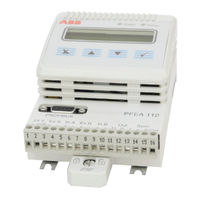
ABB PFEA 112 User Manual (216 pages)
Web Tension Systems with Tension Electronics
Brand:
ABB
| Category:
Measuring Instruments
| Size: 7 MB
Table of Contents
Table of Contents
3
Chapter 1 Introduction
11
About this Manual
11
Cyber Security Disclaimer
11
WEEE: Waste Electrical and Electronic Equipment
11
How to Use this Manual
12
Getting Started
12
Saving Actual Data and Settings at Commissioning
12
About this System
13
Safety Instructions
14
Personnel Safety
14
Equipment Safety
14
The Measuring Technique Based on Pressductor® Technology
15
Chapter 2 Installation
17
About this Chapter
17
Safety Instructions
17
Mounting the Load Cells
17
Installing the Electronic Unit
18
Selecting and Routing the Cabling
18
Recommended Cabling
18
Interference
20
Synchronization
20
Mounting the Tension Electronics PFEA111/112
21
IP 65-Version (NEMA 4)
21
IP 20-Version (Unsealed)
23
Earthing
24
Installing MNS Select Floor Cabinet
25
Mounting Cabinets Together
25
Mounting Cabinets to the Floor
25
Space Requirements
26
Installing Junction Box PFXC 141
27
Connecting the Load Cells
28
Connecting Optional Units
29
Insulation Amplifier PXUB 201 (Only for the IP 20-Version)
29
Power Supply Unit Sd83X
29
Chapter 3 Commissioning
31
About this Chapter
31
Safety Instructions
31
Necessary Equipment and Documentation
31
Using the Panel Buttons
32
Navigating and Confirming
32
Changing Numerical Values and Parameters
32
Menu Overview
33
Step-By-Step Commissioning Guide
34
Performing Basic Settings
35
Performing a Fast Setup
35
Performing Fast Setup Using Hanging Weights
36
Performing Fast Setup Using Wrap Gain
38
Checking Load Cell Signal Polarity
39
Checking Load Cell Function
39
Performing a Complete Setup
40
Overview
40
Complete Setup Sequence
41
Presentation Menu
41
Set Language
41
Set Unit
41
Set Web Width
42
Set Decimals
42
Set Object
43
Nominal Load
44
Zero Set
45
Set Wrap Gain
46
Voltage Output
48
Current Output
50
Miscellaneous Menu
52
Profibus
52
Set Factory Default
52
Service Menu
53
Maximum Load / Present Offset
54
Reset A/B
54
Simulation Function
54
Profibus DP Communication with PFEA112
55
General Data about Profibus DP
55
Master-Slave Communication
55
Profibus Physical Media
56
Commands through Profibus
57
Handling of Measurement Data through Profibus
58
Miscellaneous Meny
58
Scaling of Profibus Measuring Values
59
Filtering of Profibus Measuring Values
60
Input Buffer, Communication Block from PFEA112 to PLC
61
Output Buffer, Communication Block from PLC to PFEA112
61
Commissioning of Optional Units
62
Chapter 4 Operation
65
About this Chapter
65
Safety Instructions
65
Operating Devices
65
Start-Up and Shut-Down
66
Start-Up
66
Shut-Down
66
Normal Run
66
Measuring Values on the Display
67
Operator Menus
68
Web Tension
69
Standard Roll (Two Load Cells)
69
Single Side a or Single Side B Measurement (One Load Cell)
69
Error and Warning Messages
69
Chapter 5 Maintenance
71
About this Chapter
71
Preventive Maintenance
71
Chapter 6 Fault-Tracing
73
About this Chapter
73
Safety Instructions
73
Interchangeability
74
Necessary Equipment and Documentation
74
Fault-Tracing Procedure
75
Error and Warning Messages in PFEA111/112
76
Error Messages
76
Warning Messages
76
Fault Symptoms and Measures
77
Warnings and Errors Detected by the Tension Electronics
79
Errors
79
Flash Memory Error
79
EEPROM Memory Error
79
Supply Error
79
Load Cell Excitation Error
80
Warnings
80
Profibus Communication Problem
80
Synchronization Problem
80
Changing to Single Side Measurement if One Load Cell Is Faulty
81
Changing Load Cells
82
Appendix A Technical Data for Tension Electronics PFEA111/112
83
About this Appendix
83
Definitions Used in the Web Tension Systems
84
Coordinate System
85
Technical Data
86
Factory Default Settings
89
Optional Units
90
Insulation Amplifier PXUB 201
90
Power Supply Unit Sd83X
91
Junction Box PFXC 141
91
Drawings
92
Dimension Drawing 3BSE017052D64, Rev. D
92
Dimension Drawing 3BSE029997D0064, Rev. a
93
Profibus DP - GSD File for PFEA112
94
Appendix B PFCL 301E - Designing the Load Cell Installation
97
About this Appendix
97
Basic Application Considerations
97
Step-By-Step Guide for Designing the Load Cell Installation
98
Installation Requirements
99
Mounting Alternatives, Calculating Force and Calculating Wrap Gain
100
Horizontal Mounting
100
Inclined Mounting
101
Force Calculation for Measurement with a Single Load Cell
102
The most Common and Simple Solution
102
Force Calculation When the Web Is Not Centered on the Roll
103
Mounting the Load Cells
104
Routing the Load Cell Cable
104
Connecting the Load Cell Extension Cable
104
Technical Data
105
Cable Diagram 3BSE028140D0065, Page 2/5, Rev. C
107
Mounting Instruction, Cable Connector, 3BSE019064, Rev. a
108
Dimension Drawing, 3BSE015955D0094, Rev. D
109
Assembly Drawing, 3BSE015955D0096, Rev. C
110
Appendix C PFTL 301E - Designing the Load Cell Installation
111
About this Appendix
111
Basic Application Considerations
111
Step-By-Step Guide for Designing the Load Cell Installation
112
Installation Requirements
113
Mounting Alternatives, Calculating Force and Calculating Wrap Gain
114
Horizontal Mounting
114
Inclined Mounting
115
Force Calculation for Measurement with a Single Load Cell
116
The most Common and Simple Solution
116
Force Calculation When the Web Is Not Centered on the Roll
117
Mounting the Load Cells
118
Routing the Load Cell Cable
118
Connecting the Load Cell Extension Cable
118
Technical Data
119
Cable Diagram 3BSE028140D0065, Page 1/5, Rev. C
121
Mounting Instruction, Cable Connector, 3BSE019064, Rev. a
122
Dimension Drawing, 3BSE019040D0094, Rev. C
123
Assembly Drawing, 3BSE019040D0096, Rev. C
124
Appendix D PFRL 101 - Designing the Load Cell Installation
125
About this Appendix
125
Basic Application Considerations
125
Step-By-Step Guide for Designing the Load Cell Installation
126
Installation Requirements
127
Load Cell Orientation Depending on Measurement Direction
128
Mounting Alternatives, Calculating Force and Calculating Wrap Gain
129
Horizontal Mounting
129
Inclined Mounting
130
Force Calculation for Measurement with a Single Load Cell
131
The most Common and Simple Solution
131
Force Calculation When the Web Is Not Centered on the Roll
132
Mounting the Load Cells
133
Mounting with Brackets
135
Mounting Screws for the Load Cells
136
Routing the Load Cell Cable
136
Technical Data
137
Cable Diagram, 3BSE028140D0065, Page 3/5, Rev. C
139
Cable Diagram, 3BSE028140D0065, Page 4/5, Rev. C
140
Dimension Drawing 3BSE004042D0003, Page 1/2, Rev. O
141
Dimension Drawing, 3BSE004042D0003, Page 2/2, Rev. O
142
Dimension Drawing, 3BSE026314, Rev
143
Dimension Drawing, 3BSE027249, Rev
144
Dimension Drawing, 3BSE004042D0066, Rev
145
Dimension Drawing, 3BSE004042D0065, Rev
146
Dimension Drawing, 3BSE010457, Rev. B
147
Appendix E PFTL 101 - Designing the Load Cell Installation
149
About this Appendix
149
Basic Application Considerations
149
Step-By-Step Guide for Designing the Load Cell Installation
150
Installation Requirements
151
Mounting Alternatives, Calculating Force and Calculating Wrap Gain
152
Horizontal Mounting
152
Inclined Mounting
153
Force Calculation for Measurement with a Single Load Cell
154
The most Common and Simple Solution
154
Force Calculation When the Web Is Not Centered on the Roll
155
Mounting the Load Cells
156
Routing the Load Cell Cable
157
Technical Data
158
Cable Diagram 3BSE028140D0065, Page 3/5, Rev. C
160
Cable Diagram 3BSE028140D0065, Page 4/5, Rev. C
161
Cable Diagram 3BSE028140D0065, Page 5/5, Rev. C
162
Dimension Drawing, 3BSE004171, Rev. B
163
Dimension Drawing, 3BSE004995, Rev. C
164
Dimension Drawing, 3BSE023301D0064, Rev. B
165
Dimension Drawing, 3BSE004196, Rev. C
166
Dimension Drawing, 3BSE004999, Rev. C
167
Dimension Drawing, 3BSE023223D0064, Rev. B
168
Dimension Drawing, 3BSE012173, Rev. F
169
Dimension Drawing, 3BSE012172, Rev. F
170
Dimension Drawing, 3BSE012171, Rev. F
171
Dimension Drawing, 3BSE012170, Rev. F
172
Appendix F PFCL 201 - Designing the Load Cell Installation
173
About this Appendix
173
Basic Application Considerations
173
Step-By-Step Guide for Designing the Load Cell Installation
174
Installation Requirements
175
Mounting Alternatives, Calculating Force and Calculating Wrap Gain
176
Horizontal Mounting
176
Inclined Mounting
177
Force Calculation for Measurement with a Single Load Cell
178
The most Common and Simple Solution
178
Force Calculation When the Web Is Not Centered on the Roll
179
Mounting the Load Cells
180
Preparations
180
Mounting
180
Cabling for Load Cell PFCL 201CE
182
Technical Data Load Cell PFCL 201
183
Cable Diagram, 3BSE028140D0065, Page 3/5, Rev. C
185
Cable Diagram, 3BSE028140D0065, Page 4/5, Rev. C
186
Dimension Drawing, 3BSE006699D0003, Rev. F
187
Dimension Drawing, 3BSE029522D0001, Rev. B
188
Dimension Drawing, 3BSE006699D0006, Rev
189
Dimension Drawing, 3BSE006699D0005, Rev. J
190
Dimension Drawing, 3BSE006699D0004, Rev. H
191
Appendix G PFTL 201 - Designing the Load Cell Installation
193
About this Appendix
193
Basic Application Considerations
193
Step-By-Step Guide for Designing the Load Cell Installation
194
Installation Requirements
195
Mounting Alternatives, Calculating Force and Calculating Wrap Gain
196
Horizontal Mounting
196
Inclined Mounting
197
Force Calculation for Measurement with a Single Load Cell
198
The most Common and Simple Solution
198
Force Calculation When the Web Is Not Centered on the Roll
199
Mounting the Load Cells
200
Preparations
200
Adapter Plates
200
Mounting
200
Cabling
202
Technical Data Load Cell PFTL 201
203
Cable Diagram, 3BSE028140D0065, Page 3/5, Rev. C
205
Cable Diagram, 3BSE028140D0065, Page 4/5, Rev. C
206
Dimension Drawing, 3BSE008723, Rev. D
207
Dimension Drawing, 3BSE008904, Rev. D
208
Dimension Drawing, 3BSE008724, Rev. F
209
Dimension Drawing, 3BSE008905, Rev. G
210
Dimension Drawing, 3BSE008917, Rev. H
211
Dimension Drawing, 3BSE008918, Rev. G
212
Appendix H Actual Data and Settings at Commissioning
213
Document the Commissioning in this Form
213
Advertisement
Related Products
ABB PFEA 111
ABB PFEA 113
ABB PFEA 122
ABB PFCL 201
ABB PFTL 101
ABB ProcessMaster 300
ABB SACE PR010/T
ABB Gas Sampling Probe 2
ABB PLMU Series
ABB PLR Series
ABB Categories
Industrial Equipment
Controller
Measuring Instruments
Battery Charger
DC Drives
More ABB Manuals
Login
Sign In
OR
Sign in with Facebook
Sign in with Google
Upload manual
Upload from disk
Upload from URL