Advertisement
Quick Links
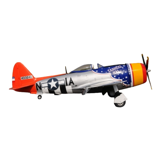
CARF-Models P-47
P-47 Thunderbolt
History
Long before "super-sizing" became synonymous with American culture, Republic Aircraft
unveiled the P-47 Thunderbolt. An Alexander Kartvelli design, the P-47 was the largest single
seat fighter aircraft of WWII. With eight .50 caliber machine guns and provisions for bombs,
rockets and drop tanks, fully loaded, the Thunderbolt could weigh as much as 8 tons!
Although the obvious lineage to previous Kartvelli designs, the P-35 and P-43, is apparent, the
P-47 was a completely new and much larger aircraft built to accommodate the most powerful
piston engine at the time, the Pratt and Whitney R-2800 radial. In typical Kartvelli fashion, form
followed function as the engine's turbo-supercharger was buried in the belly of the beast, thus,
creating its characteristic profile.
It is said the Thunderbolt was nicknamed "the Jug" by the British who considered the shape of
the fuselage as similar to the glass milk "jugs" of the time; or because upon first glance, someone
declared the ungainly fighter to be a "Juggernaut!" Whatever the origins, the name "Jug" is used
to this day in reference to the P-47.
First deployed as a long-range escort fighter, the P-47 really came into its own when it
transitioned to ground attack, amassing an incredible obituary of axis vehicles: In addition to
www.carf-models.com
Instruction Manual
1
Advertisement

Subscribe to Our Youtube Channel
Related Manuals for Carf-Models P-47 Thunderbolt


Summary of Contents for Carf-Models P-47 Thunderbolt
- Page 1 History Long before “super-sizing” became synonymous with American culture, Republic Aircraft unveiled the P-47 Thunderbolt. An Alexander Kartvelli design, the P-47 was the largest single seat fighter aircraft of WWII. With eight .50 caliber machine guns and provisions for bombs,...
- Page 2 CARF-Models P-47 www.carf-models.com bringing down 3,916 enemy aircraft, the Thunderbolt destroyed 6,000 tanks, 9,000 locomotives, 68,000 trucks and 86,000 rail wagons in 746,000 sorties of all types. In Europe, Thunderbolts flew more sorties than P-51s, P-38s and P-40s combined. In the Pacific, Colonel Neel E. Kearby of the Fifth Air Force destroyed 22 Japanese aircraft and was awarded the Medal of Honor for an action in which he and his Thunderbolt downed six enemy fighters on a single mission.
-
Page 3: Liability Exclusion And Damages
Unless otherwise prescribed by binding law, the obligation of the CARF-Models to pay compensation is excluded, regardless of the legal argument employed. This applies to personal injury, death, damage to buildings, loss of turnover and business, interruption of business or other direct and indirect consequent damages. - Page 4 Landing Gear and Engine Selection The CARF-Models P-47 is designed for retractable main and tail gear. In collaboration with Sierra Giant Scale, custom retracts (#270500) are available and strongly recommended as an integral component of your new Thunderbolt. The custom scale struts are designed to compress during the retraction process so that the full scale length when extended is available, while compression during retraction allows a scale strut and wheel bay position in the wing.
-
Page 5: Danger Zones
CARF-Models P-47 www.carf-models.com Propeller Arc DANGER ZONES NO!!! SECURE aircraft BEFORE starting engine! MAKE SURE that all spectators are FAR in front OR behind the aircraft when running engine! The P-47 Thunderbolt... - Page 6 • P-47 in Scale and Detail by Bert Kinzey • Scale Aviation Modeller International; Volume 10, Issue 2; Feb. 2004 • P-47 Thunderbolt in Action; Squadron Signal Publications • P-47 Thunderbolt in Action No. 208 by Larry Davis; Squadron Signal...
- Page 7 CARF-Models P-47 www.carf-models.com Let us Begin – As with any new kit, a thorough INVENTORY is in order. To that end, a comprehensive parts list and numbered pictures have been provided as follows: Identifier Quantity Item Description Fuselage; includes air outlets and tail gear...
- Page 8 CARF-Models P-47 www.carf-models.com...
- Page 9 CARF-Models P-47 www.carf-models.com...
- Page 10 CARF-Models P-47 www.carf-models.com...
- Page 11 CARF-Models P-47 www.carf-models.com...
- Page 12 CARF-Models P-47 www.carf-models.com...
- Page 13 CARF-Models P-47 www.carf-models.com...
- Page 14 CARF-Models P-47 www.carf-models.com...
-
Page 15: Recommended Accessories
CARF-Models P-47 www.carf-models.com Recommended Accessories Accessory Item # 270500 Scale Main Retracts 270550 Scale 7" Main Wheels (2) 270600 Scale Retractable Tail gear 270650 Scale Tail wheel 270700 Scale 4-blade Propeller 270800 Pneumatic Completion Pack... - Page 16 CARF-Models P-47 www.carf-models.com Handling the P-47 A cradle can be created from the included packing materials to assist in holding the fuselage for the installation of radio and other internal workings. The following photos are self-explanatory:...
- Page 17 CARF-Models P-47 www.carf-models.com...
- Page 18 CARF-Models P-47 www.carf-models.com CONSTRUCTION The CARF-Models P-47 features precut servo pockets and mounting holes with spacing appropriate for JR digital servos – the 8611A will drop right in. Larger servo screws are provided and strongly recommended for all servo installations.
- Page 19 CARF-Models P-47 www.carf-models.com The elevator servo should be mounted in the pre-cut pocket using the provide servo screws. The pushrod is then threaded into the pre-installed elevator torque rod ball link. Retractable Tail wheel Your P-47 is designed to accommodate the Sierra Precision tail wheel unit. Locate the included...
- Page 20 CARF-Models P-47 www.carf-models.com Provided bolts and washers for securing mounting plate to inside fuselage mount Mount the Sierra tail wheel unit on the ply mounting plate using 6x32 bolts and washers (not provided). Be sure to use Blue thread locker on all screws and nuts!
- Page 21 CARF-Models P-47 www.carf-models.com View from inside fuselage Pre-installed tail wheel mount inside fuselage. Tail wheel opening The tail wheel unit mounting plate is bolted inside the fuselage to the pre-installed mounting plate using the provided bolts and washers.
- Page 22 CARF-Models P-47 www.carf-models.com Installing tail wheel mounting plate mounting bolts can be challenging…Get all bolts started before tightening. IF you have REALLY LONG ARMS, you can reach the forward plate bolts from the wing opening. USE THREAD LOCKER! Forward mounting bolts...
- Page 23 CARF-Models P-47 www.carf-models.com Tail Wheel steering cables Locate the tail wheel and rudder servo hardware pack. The pack contains four cables: (2) 130cm cables and (2) 100cm cables. The tail wheel cables are the shorter, 100cm pair. Cable is looped...
- Page 24 CARF-Models P-47 www.carf-models.com Loop should be pulled tight, then swage is CRIMPED FLAT with pliers or vice grips. Excess cable is cut off. CRIMP SWAGES with pliers or vice grips. Squeeze VERY tight so that cables cannot pull free.
- Page 25 CARF-Models P-47 www.carf-models.com Rudder / Tail wheel Servo The rudder hardware pack is used to make the ball link attachment points at the rudder servo. The tail wheel links are positioned outboard on the arm; rudder links on the inner holes. See photos: Mount the rudder servo in the pre-installed tray using the provided servo screws.
- Page 26 CARF-Models P-47 www.carf-models.com NOTE: Due to the location of the rudder tray, this is admittedly a challenging procedure! Take your time; do it right. Check the cable lengths several times BEFORE pulling loops tight and crimping. When checking cable length and pulling cable tight, Rudder servo arm MUST remain stationary and neutral.
- Page 27 CARF-Models P-47 www.carf-models.com Completed Tail wheel steering cables Vertical Fin and Rudder Installation Locate the vertical fin, 20mm x 150mm aluminum fin tube, and rudder. Also find the rudder hinge pin (0.075” wire ) and knurled nylon retention nut. Trial fit.
- Page 28 CARF-Models P-47 www.carf-models.com Fin retention Nut The rudder clevises and eyelets are part of the rudder hardware pack. Assemble clevises, eyelets and jam nuts as pictured (NOTE: included hardware may be slightly different than shown and attach to rudder horns. Trial fit rudder to fin using supplied rudder hinge pin. Remove the rudder and drill two 10mm holes in the fin former for rudder cables.
- Page 29 CARF-Models P-47 www.carf-models.com that rudder deflects smoothly left and right with no detected binding. Once complete, secure the rudder so that it is held firmly centered. This can be done with two rulers, clamped on either side of the fin and rudder.
- Page 30 CARF-Models P-47 www.carf-models.com Horizontal Stab and Elevators NOTE: Remove torque rod arm retention nut, apply thread-locking compound, and re-tighten. Locate the 20mm x 380mm aluminum stab tube. Remove the stab retention bolts from the tube and slide tube into position. The left and right stab and elevator assemblies should be trial fit.
- Page 31 CARF-Models P-47 www.carf-models.com the stab and elevator and trial fit the elevator retention bolts into the CF torque rod to verify correct angle of insertion and proper thread ‘purchase.’ Equipment Tray Locate the milled wood parts for the equipment tray. The tray mounting lugs are constructed from the pre-milled parts as shown.
- Page 32 CARF-Models P-47 www.carf-models.com LOCATION of the equipment tray DEPENDS UPON ENGINE CHOICE: IF using the Moki 215 or 250 radial, the equipment tray must be installed just aft of the cockpit; IF using a DA120 or similar engine, the equipment tray must be installed forward of the front wing mounts.
- Page 33 CARF-Models P-47 www.carf-models.com Using the included bolts and Nylon nuts, attach the front equipment tray mounts to the tray and set into position; use spring clamps to hold while marking the mount locations on the fuselage. Remove the tray and lightly sand the mounting areas in preparation for epoxy.
- Page 34 CARF-Models P-47 www.carf-models.com Mix 30 minute epoxy with cut glass fibers and apply to equipment tray mounts. When clamping equipment tray into position keep equipment tray free of any epoxy!
- Page 35 CARF-Models P-47 www.carf-models.com When the epoxy has set on the front mounts, locate the position of the rear mounts; mark the mounting holes and enlarge them to line up with the tray. Mark the position of the rear mounts; remove the tray; sand, clean and epoxy rear mounts in the same manner as the front mounts.
- Page 36 CARF-Models P-47 www.carf-models.com...
- Page 37 CARF-Models P-47 www.carf-models.com WINGS - Flaps Locate the Flap servo hardware bag and make two pushrods as shown. Install the flap servos inside gear pockets using the provided servo screws. Pushrod length will vary w/servos and arms used. The measurement below is approximate.
- Page 38 CARF-Models P-47 www.carf-models.com WINGS – Ailerons NOTE: Please check ALL hinges on both ailerons and flaps for the installation of ‘E’ clip retainers. While CARF quality checks are thorough, they are not perfect. IF any clips or hinge pins are missing, contact your CARF Sales Rep for immediate replacement.
- Page 39 CARF-Models P-47 www.carf-models.com As they say, “You cannot make an omelet without breaking a few eggs!” – to sacrifice a Philips screwdriver for the greater good of aileron servo installation… a fair trade INDEED! Brass tubing is soldered to as the extension between tip and base to create the needed tool.
- Page 40 CARF-Models P-47 www.carf-models.com 35 cm The screw driver is inserted through the outboard flap pivot point.
- Page 41 CARF-Models P-47 www.carf-models.com Servo mounting screws accessed from outboard flap pivot opening. On some early production P-47s, the aileron pushrod exit hole was not drilled in the wing trailing edge spar. If yours does not have the exit hole, find the correct location on the spar by lining up the aileron horn with servo horn.
- Page 42 CARF-Models P-47 www.carf-models.com Aileron servo installed and pushrod connected to INNER hole. Aileron Horn is located on top of aileron next to center hinge. A short piece of gas fuel tubing is used to secure the clevis to the horn. Check for proper aileron defection and no binding!
- Page 43 CARF-Models P-47 www.carf-models.com The Aileron Servo Hatches can be separated. Lightly sand the edges of the hatches smooth and install using small screws, provided. The hatches can be painted to match using CARF Fine Silver paint Item Number: 970024 Cockpit Air Intake The P-47 cockpit was fed fresh air through a scoop on the leading edge of the right wing.
- Page 44 CARF-Models P-47 www.carf-models.com...
- Page 45 It is assumed that if you have chosen to build this aircraft, you are an experienced modeler with previous scale war bird experience. Despite the high degree of pre-fabrication, it must be understood the CARF-Models P-47 is a complex miniature aircraft that requires skill, patience and care to complete.
- Page 46 CARF-Models P-47 www.carf-models.com Position the gear such that they are centered within the gear cut-outs and also check gear retraction (with wheels mounted) to make sure there is ample clearance around gear scissors and wheels to clear wing skins at all positions. A hand pump is very handy for extending and retracting gear for testing purposes.
- Page 47 CARF-Models P-47 www.carf-models.com PROTECT YOUR WING WHEN DRILLING… insert a thick piece of wood so that your drill does not penetrate the top wing skin! Check and re-check for proper clearances and smooth gear retraction. Wheel angle is adjusted by loosening the locking studs at the base of the gear struts.
- Page 48 CARF-Models P-47 www.carf-models.com Once spacer blocks are in place, some additional clearance may be required for easy gear installation and removal COMPLETED INSTALL Gear Doors Proper opening and closing of gear doors is JUST as critical as proper gear retraction. There are several ways to accomplish this using the Robart cylinders included in the pneumatic support kit.
- Page 49 CARF-Models P-47 www.carf-models.com The air cylinder piston/rod is threaded for 2-56. An SAE threaded insert is used (not included ) to connect ball links to rod. The ball links will securely thread onto any 2-56 stock.
- Page 50 CARF-Models P-47 www.carf-models.com Air Cylinder mounting pads are built from the included wood parts as shown: Completed Mount Position and mount cylinder as pictured (left) then epoxy ply mount into position (right) to line up with gear door horn.
- Page 51 CARF-Models P-47 www.carf-models.com NOTE: If ‘C’ clip is not located on the accessible side of air cylinder, be sure to remove and reinstall pivot pin and C clip so that it is. This will allow easier cylinder replacement should it ever be required.
- Page 52 CARF-Models P-47 www.carf-models.com IF additional wheel clearance is required, sand wing skin as shown (below left) to allow gear door to open wider. Additional door throw may require ball link adjustment. DO NOT adjust gear compression link for additional wheel compression / clearance. This is factory set!
- Page 53 CARF-Models P-47 www.carf-models.com Wheel Covers The wheel covers are mounted to the gear forks using the supplied countersunk screws. The holes can be correctly located as follows: Once holes are drilled through the wheel cover and a few millimeters into gear legs, remove wheel cover.
- Page 54 CARF-Models P-47 www.carf-models.com The wheels covers will most likely require spacing away from the gear legs for proper and secure fit. Using scrap wood, make spacers, contouring to shape until the wheel cover can be fastened using both screws; it should fit into wheel opening and not interfere with gear retraction.
- Page 55 CARF-Models P-47 www.carf-models.com Strut Covers Fitting strut covers requires PATIENCE. There is no specific manner in which to guarantee a perfect fit…this is a trial and error process in which you “creep up” on the proper fit. However, the following photos and tips will minimize the potential for errors! From the Wing hardware bag, locate the strut cover hinge wire and sleeve.
- Page 56 CARF-Models P-47 www.carf-models.com Hinge pin ends will be inserted into ball links. Once the correct sleeve/pivot position is found, a mixture of epoxy and cut glass is used to bond sleeve to strut cover.
- Page 57 CARF-Models P-47 www.carf-models.com...
- Page 58 CARF-Models P-47 www.carf-models.com The hinge pin wire is cut to length a little bit at a time until the proper length is achieved such that the strut cover will lay perfectly flat when the gear are fully retracted: Make SMALL cuts to achieve correct length Locate the large Robart hinge point from the hardware pack.
- Page 59 CARF-Models P-47 www.carf-models.com NOTE the distance from the bottom edge NOTE that hinge end must be cut off where it of strut cover to hinge pivot point – extends beyond the edge of the gear cover. Approx. 6mm (1/4”) When satisfied with the fit and operation, glue components with a mixture of epoxy and cut glass.
- Page 60 CARF-Models P-47 www.carf-models.com When 100% satisfied with the operation of the strut cover, abrade the hinge pins and clean with alcohol. Apply epoxy and cut glass mixture to pins and ball links. Insert pins, wiping any excess epoxy. Retract the gear fully and tape the strut cover tightly closed. Allow to dry.
- Page 61 CARF-Models P-47 www.carf-models.com Prepping for Pneumatics If you are so inclined, now is the time to paint the interior areas of the wheel wells and gear doors. Everyone has their favorite methods for prepping and painting. The following shows an easy method of painting with water-based acrylic in the military spec Zinc Chromate Green.
- Page 62 CARF-Models P-47 www.carf-models.com Pneumatics Assuming you have acquired the CARF-Models P-47 Pneumatics Support kit (#270800), the following is a logical application of the included colored high pressure air lines: Green = gear extended = gear retracted Blue = air pressure...
- Page 63 CARF-Models P-47 www.carf-models.com...
- Page 64 CARF-Models P-47 www.carf-models.com If you have not already done so, add servo extensions to the aileron and flap servos. An aileron extension is easily pulled through the wing using any long slender rod. Use commercially available servo connector clips or heat shrink tubing to secure the extensions to the servo leads so...
- Page 65 CARF-Models P-47 www.carf-models.com Tail wheel Pneumatics and Doors Connect the extend/retract air lines using the same convention as the main retracts. The tail wheel doors are mechanically opened and closed using two sprung wires. Green = open Red = close...
- Page 66 CARF-Models P-47 www.carf-models.com Wing – installation The wing halves are joined using the two aluminum wing tubes: 30x 610mm and 40x 610mm. Once joined, the wing is bolted to the fuselage using the 4 supplied wing bolts – two long, two short.
- Page 67 CARF-Models P-47 www.carf-models.com Engine Dome – Moki Locate the carbon fiber engine mounting dome and engine hardware pack. The dome mounting holes must be enlarged for the mounting bolts – the larger (7) bolts are for mounting the engine and dome; the smaller (3) bolts are for mounting the cowl. The engine dome “TOP” is etched at the factory –...
- Page 68 CARF-Models P-47 www.carf-models.com Make a cardboard mounting template for the Moki, marking mounting holes and clearance for carburetor and choke. The template will be used to transfer these locations to the engine dome. Engine mounting holes and carburetor opening must be drilled out. Laminate the two...
- Page 69 CARF-Models P-47 www.carf-models.com The engine dome is prepped for gluing; apply 30 minute epoxy to the plywood backing plate. Use the engine, blind nuts and mounting bolts to clamp everything in place and set aside. NOTE: it is a good idea to apply some epoxy to the blind nuts so they cannot come loose. AVOID getting epoxy on the screw threads! Once set, remove the engine from the dome;...
- Page 70 CARF-Models P-47 www.carf-models.com Tighten dome Four blind mounting nuts installed bolts to on backside embed blind of firewall nuts into from inside firewall fuselage Bolt engine onto dome and check / verify RIGHT THRUST.
- Page 71 CARF-Models P-47 www.carf-models.com Throttle Servo and Ignition module Remove the engine dome and drill large pilot holes in the firewall center section and ignition cable portal. Use a coping saw or jig saw to complete the firewall cut out. Use a high speed sanding drum for the portal.
- Page 72 CARF-Models P-47 www.carf-models.com You may choose to prime and paint the firewall. This is optional and not required Servo Tray Locate the Throttle Servo Hardware pack. The throttle servo tray is built as shown using thick CA, epoxy or aliphatic resin glue. The blind nuts are pressed into place and should also be secured with a small amount of glue so they cannot back out.
- Page 73 CARF-Models P-47 www.carf-models.com Throttle Servo Mounting holes drilled out Moki Ignition Module mounting holes are also already drilled in the back of the firewall, but must be drilled through. Ignition mounting screws and nuts are not part of the hardware pack.
- Page 74 CARF-Models P-47 www.carf-models.com The module and throttle servo tray are mounted where shown above. Throttle pushrod utilizes ball link, clevis and jam nut. Rubber grommet to protect fuel line Pushrod and fuel line locations on engine dome. Throttle servo and pushrod installed...
- Page 75 CARF-Models P-47 www.carf-models.com Bolt engine into position and check/adjust throttle pushrod...
- Page 76 CARF-Models P-47 www.carf-models.com Set the cowl in place and ADMIRE YOUR THUNDERBOLT!
- Page 77 CARF-Models P-47 www.carf-models.com NOTE: The fuselage cradle can be utilized to hold fuselage inverted or upright. This may be more convenient than handling the aircraft with its massive wings in place! COWL Locate the cowl baffle and check fit. Some sanding may be necessary for proper fit.
- Page 78 CARF-Models P-47 www.carf-models.com With the cowl mounted, tape the baffle into position. Look at a 3-view of the Thunderbolt if you are unsure of the correct positioning. When satisfied, mark the location and remove the cowl. Lightly sand the gluing surfaces;...
- Page 79 CARF-Models P-47 www.carf-models.com Service Hatch Radio equipment switches, charge jacks, and air fill can be hidden behind a scale-like access hatch on the fuselage side, just beneath the cockpit. Ultimately, it is up to the modeler to decide. Hardware for the following option is not included: Thin ply is used to make a ‘frame’...
- Page 80 CARF-Models P-47 www.carf-models.com Air Outlet and Turbo-Supercharger Outlet Covers Locate the Air Outlet and Turbo-supercharger outlet covers (Parts ID # 8 and #9). See the following photos for correct placement. CA or epoxy can be used. Surfaces should be lightly sanded and trial fit before applying adhesive.
- Page 81 CARF-Models P-47 www.carf-models.com Air Support It is highly recommended that you take this opportunity to test your air system, getting familiar with the operation of the JET Tronics valves and other components integral to the retractable gear. This is best done BEFORE installation into the aircraft.
- Page 82 CARF-Models P-47 www.carf-models.com Radio and Pneumatics installation The following is a pictorial of one option. Your installation will depend upon your choice of on- board radio electronics as well as other factors. Power Distribution Unit mounted on top of equipment...
- Page 83 CARF-Models P-47 www.carf-models.com A switch mounting plate is built from scrap hardwood or ply. This will be epoxied inside the fuselage directly behind Service Hatch. Relief in plate is for Festo one-way Air Fill Valve. JET Tronics Air Valves and Festo T mounted on plywood, which is epoxied into position:...
- Page 84 CARF-Models P-47 www.carf-models.com Service Hatch...
- Page 85 CARF-Models P-47 www.carf-models.com Pneumatic Completion At this point in the project, we have installed retracts, wing air lines, TW air lines, air valves, and radio. It is time to complete the pneumatics installation such that correct and reliable gear and door operation can be achieved and repeated MANY times on the bench.
- Page 86 CARF-Models P-47 www.carf-models.com Pneumatics Schematic...
- Page 87 CARF-Models P-47 www.carf-models.com EXIT nipples JET Tronics Valve – Drives JET Tronics Valve – ‘T’ Fittings and Main Gear Drives Tail Wheel and Air Lines for TW Green = Open/gear down Gear Doors unit. Air lines = Closed/gear up going forward for Main Gear Doors Builder’s NOTE: Keep your installation clean,...
- Page 88 CARF-Models P-47 www.carf-models.com All air and servo connectors are hidden beneath the belly pan (fuselage bottom hatch) RIGHT WING HALF LEFT WING HALF NOTE: 25mm (1 inch) exit holes cut in wing halves. Add rubber grommets (available at hardware stores)
- Page 89 CARF-Models P-47 www.carf-models.com Both JET Tronics Valves must be Reset with NO throttling (the Default setting is 3 seconds of throttling – this must eliminated). Reset the JET Tronics valves by turning off receiver, holding both blue valve buttons down at the same time, then powering up receiver. This should reset valves to no throttling of either output.
- Page 90 Turbo-Supercharger. The location of these waste gates lend themselves perfectly to scale exhaust outlets. The prototype CARF-Models Thunderbolt utilized canister headers for exhaust extensions. Another option is corrugated copper pipe utilized for hot water heater installations and found at most home improvement and hardware stores The Moki exhaust outlets are 20mm (3/4 inch) in diameter.
- Page 91 CARF-Models P-47 www.carf-models.com The finished exhaust extensions are approximately 12 inches (30cm) long. Cut the copper stock so that there is plenty of material with which to work. Trim tubing length to fit into the tapered end such that when inserted into exhaust exit, it is flush with fuselage.
- Page 92 CARF-Models P-47 www.carf-models.com A “Waste Gate” can be made from thin tin stock and brazed into position as shown: Soldering performed only when tubing is removed from the aircraft. ‘Hose clamps’ are utilized to secure the exhaust extensions to the Moki outlets. Slots should be...
- Page 93 CARF-Models P-47 www.carf-models.com NOTE: Find Exhaust cooling addendum at end of manual...
-
Page 94: Fuel Tank
CARF-Models P-47 www.carf-models.com Fuel Tank Whether using the 250cc Moki or a 120cc DA, 32 ounces of gas (1 liter) will be plenty; the tank tray is designed to accommodate a 1 liter sized tank. It is always recommended that you install “fuel barbs”... - Page 95 CARF-Models P-47 www.carf-models.com Canopy The canopy pieces require the ‘window’ material to be removed. This is best accomplished with an abrasive wheel and high speed tool. Use proper eye and breathing protection: Use a file or sanding tool to accurately finish and smooth cut outs.
- Page 96 CARF-Models P-47 www.carf-models.com Scale modelers who intend to compete with the Thunderbolt will no doubt want a scale sliding canopy mechanism. There are several online articles as well as companies that offer hardware designed to create a sliding canopy. The following is one option that eliminates the complexity of canopy rails, yet achieves the OPEN/CLOSED positions while making the canopy readily removable for painting or cockpit service.
- Page 97 CARF-Models P-47 www.carf-models.com MAGNET...
- Page 98 CARF-Models P-47 www.carf-models.com Locate the ‘canopy open’ position and mark the magnet locations, gluing them into place the same way as the forward ‘canopy closed’ magnets. USE at least FOUR magnet pairs to firmly hold canopy in place. Locating pins are added last.
- Page 99 CARF-Models P-47 www.carf-models.com With the canopy frame firmly taped into position, the opposing underside magnets are glued into position (they will automatically ‘snap’ to the perfect position opposite the canopy magnets). 4 additional magnet locations. Use epoxy and cut glass mixture to...
- Page 100 CARF-Models P-47 www.carf-models.com Using small metal tubes, rods or wooden dowels as a guide, drill through front canopy frame for locating pins. The pins are then epoxied into place. Trim canopy clear plastic to fit. IF painting canopy frames, do it BEFORE gluing clear plastic window material in place.
- Page 101 CARF P-47, an accurate finish should be integral to creating a truly miniature version of your favorite Thunderbolt. The surface detail of the CARF-Models P-47 lends itself to some very easy ‘weathering’ techniques that will add a great deal of character and realism to your finished project.
- Page 102 CARF-Models P-47 www.carf-models.com documentation or our personal preference requires. An abrasive ‘Scotch Brite’ pad is used to ‘burnish’ areas of high wear or heat and is perfect for giving the shiny silver topcoat a more realistic, dull, ‘scratched’ finish; the type of wear and tear that occurred in the harsh conditions of battle.
- Page 103 CARF-Models P-47 www.carf-models.com 600 grit wet/dry sand paper is used to great affect in allowing surface detail to appear. DO NOT OVERDUE IT. It is the subtle illusion of weathering that adds greatly to the realism of your airplane. IF finishing your aircraft for scale competition, it is critical that you duplicate your documentation.
- Page 104 CARF-Models P-47 www.carf-models.com Some modelers may choose to “scuff” or “burnish” the bare metal finish prior to painting. The overall effect is quite realistic.
- Page 105 CARF-Models P-47 www.carf-models.com IF you do not possess the skills to apply a quality finish, you should pursue the help of an experienced scale modeler. A project such as your Thunderbolt deserves a quality scale finish. DO NOT rush this very important step as you will be stuck with the results, good or bad.
- Page 106 CARF-Models P-47 www.carf-models.com Apply the sticky-backed Frisket to the area you wish to paint, making very sure the edges are well sealed to the surface. It is advisable to first lightly clear-coat any previously applied paints BEFORE masking and applying additional paint colors.
- Page 107 CARF-Models P-47 www.carf-models.com The stencils can now be very carefully removed to reveal your completed marking! These same techniques can be utilized for creating other authentic markings on your aircraft. The ‘120’ was created by painting over vinyl markings then carefully removing them, leaving the bare ‘metal’...
- Page 108 CARF-Models P-47 www.carf-models.com Belly Pan Using an abrasive cutting wheel and sander, remove material from the belly pan to clear the air lines and servo cables. The pan attaches with a single bolt. Using the abrasive Scotch Brite pads, the belly pan is given that “used” look.
- Page 109 CARF-Models P-47 www.carf-models.com Canopy - addendum Upon further consideration, it was decided to add a single retention bolt to the canopy. While no flight tests were conducted using only magnets and locating pins, careful attention to potential mishaps dictated the additional security. Magnets have the advantage of simple installation, easy canopy opening and complete canopy removal.
- Page 110 CARF-Models P-47 www.carf-models.com TW gear doors - addendum The gear door hinge pins are not glued at the factory to allow the builder to remove the doors for painting. It is also recommended that you remove these hinge pins and lubricate them for easier gear door actuation.
- Page 111 CARF-Models P-47 www.carf-models.com Balance and Flying The airplane balances at 25% of cord at the wing root. Measure back from the leading edge 15.5 cm - This is the correct location of the Center of Gravity. Achieve the proper CG by shifting components inside the aircraft.
- Page 112 CARF-Models P-47 www.carf-models.com When ready to land, the Thunderbolt is flown through a traditional landing pattern. Half flaps may be deployed during the downwind leg of the pattern to begin slowing the aircraft. You should not notice any tendency for the aircraft to pitch up when flaps are deployed at a reduced speed.
Need help?
Do you have a question about the P-47 Thunderbolt and is the answer not in the manual?
Questions and answers