Table of Contents
Advertisement
Quick Links
Advertisement
Table of Contents

Related Manuals for Carf-Models Ultra Flash


Summary of Contents for Carf-Models Ultra Flash
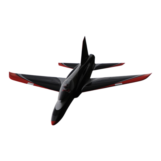
- Page 2 CARF-Models Ultra Flash New for 2010 the Ultra Flash is an updated version of the best selling Flash, designed for higher performance with a new wing and tailplane. The new wing is swept back with greater span, larger flaps and tapering section from root to tip. The swept design makes the Ultra Flash easier to balance with the lighter Li-Po cells now used by the majority of jet modellers.
- Page 4 ‘Flash’ Thank you very much for purchasing our CARF-Models ‘Ultra Flash’ sport-jet, made with the revo- lutionary Total Area Vacuum Sandwich (TAVS) technology. Please note that a few of the photos in this Instruction manual show some views from the 2 pro- totypes, so please don’t get confused by the slightly different colour schemes!
- Page 5 Attention ! This ‘jet’ aircraft is a high-end product and can create an enormous risk for both pilot and spec- tators, if not handled with care & used according to the instructions. Make sure that you operate your ‘Flash’ according to the laws and regulations governing model flying in the country of use. The engine, landing gear, servos, linkages and control surfaces have to be attached properly.
- Page 6 area when moving downwards. Centreline of hinge axis The slot needs some explanation, too. The cut line is exactly in the correct position so that the control surface slides under the wing skin smoothly. If the cut was a few mm forward or backwards, it would not work properly.
- Page 7 ‘Ronsonol’ or equivalent. This does not damage the paint, as Acetone and many other solvents will, and this is what we use at the factory. At CARF-Models we try our best to offer you a high quality kit, with outstanding value-for-money, and as complete as possible. However, if you feel that some additional or different hardware should be included, please feel free to let us know.
- Page 8 Accessories This is a list of the main additional items you will need to get your CARF Ultra Flash into the air. Some of them are mandatory, and some can be chosen by you. What we list here are highly recommended items, and have been thoroughly tested.
- Page 9 The CARF Ultra Flash if the best flying Jet possible for the money paid, there is no question about that. It is the most prefabricated and strongest design for the money paid - no question about that either.
-
Page 10: Building Instructions
Building Instructions Exhaust Nozzle The fibreglass exhaust nozzle is completely painted, fin- ished and trimmed for you at the factory. It is secured to the fuselage at the top using an M3 x 6mm button-head bolt that slides into a slot you must file in the exhaust noz- zle, and 2 sheetmetal screws at the bottom that are screwed into plywood plates glued in side the exhaust noz- zle. - Page 11 stab, and sand the edges a little if necessary for a perfect fit. Glue the milled 1.5mm ply- wood triangles under each corner of the servo bay (where the fixing screws will be) to rein- force the area, using thick CA. Sand and trim the inside edges of the servo bays to reduce the width of the lips between each corner to about 1.5 - 2mm wide.
- Page 12 ed), as shown in the photo here - as it is directly above the exhaust ducting and could be dam- aged if you have any accidental wet-starts or similar. Rudder The rudder is cut loose, hinged and the dual phenolic con- trol horns are installed at the factory, and you just need to fit the rudder servo and linkage.
- Page 13 Exhaust Duct/Thrust tube The thrust tube consists of a lightweight aluminium outer tube and a 0.25mm thick stainless steel inner tube, spotwelded together. It is designed to work with a wide range of turbines and it is, therefore, a compromise - but has already been used very successfully with several different (above) Drill Ø...
- Page 14 tral fin, as shown, to allow extra cooling air to enter the outer thrust tube - and this is especially important if you fly in high ambient temperatures. They should be approx. 60mm long and 30mm wide. On both prototypes, with these intakes, the fuselage did not get warm - even after 2 or 3 minutes of engine idling in ambient temperatures of around 30°...
- Page 15 12mm wide plywood strip included in the kit, sand to required thickness, and glue to the mounting rails with CA (photo above). Normally the turbine will need to be mounted right at the front of the engine mounting rails, against F5, so that the back edge of the outer casing (the ‘chromed’ part on Jetcats’) is about 15 - 18mm in front of the front edge of the carbon bellmouth and F6 bulkhead.
- Page 16 er as shown above. Then glue these 2 parts into the milled slots in the front engine bulkhead as shown, using epoxy. These will have M3 T-nuts glued to them to secure the upper bypass later. Trim and fit the ‘upper’ bypass. The stepped flange at the back goes over the outside of the carbon bellmouth, and if it is a tight fit you can sand the Ø140mm hole in bulkhead F6 a little.
- Page 17 needed for an electrical connector, and fix the grommets to the bypass with a small drop of thin CA. Inlet Joiner: The pre-painted inlet ducts are factory-installed, and only the back end may need trimming a little to exact length to fit the fibreglass inlet joiner.
-
Page 18: Fuel System
Fuel System. The standard Flash kit includes a single composite fuel tank (2.2 litres) that installed in the fuselage above the inlet ducts, and a hopper tank that is installed in the cock- pit area. If you are installing a turbine of 9kg thrust or more, you will also need to install the optional wing fuel tank (1.4 litres) to give reasonable length flight times. - Page 19 6mm in front of the tank. Check that it is horizontal and then tack glue to the fuselage sides with a couple of drops of thin CA. Remove the temporary packers and the tank. Prepare the inside surface of the fuselage and tank sup- port by sanding and cleaning, and glue the support in per- manently with 30 min.
- Page 20 length of the included double-sided Velcro. Our preferred method is to have a felt clunk (Webra #1121) fixed to the end of the brass feed tube inside the hopper tank, in the 3-dimensional centre of the fuel tank, which is connected to the fuel pump.
- Page 21 tank and give you the maximum fuel capacity. Included in the hardware is a felt clunk, or you can use a normal clunk if you prefer. Connect the clunk to the brass ‘feed’ tube with Tygon, and make sure that it almost reach- es the back end of the tank.
- Page 22 Nosegear All 3 Behotec C36 retract units are the identical, and there is no ‘special’ nosegear unit. See photo P11 for view of complete assembled nosegear. Assemble the nosegear as shown here. Grind a small ‘flat’ about 5mm from the chamfered end of the longest (50mm) Ø6mm ground steel connecting pin.
- Page 23 bolts to hold it in position. Then drill the other 3 holes, also (below) Sand Bulkhead F2 for inserting a bolt to keep the correct alignment after each steering arm clearance if needed. hole is drilled. Remove the retract unit and open up all the holes to Ø5.5mm for the M4 T-nuts.
- Page 24 linkages are needed. This door also gives some speed- braking effect during landing. Trim the door to fit in the opening with about 1mm gap all round. Leave the front edge of the retract opening as far backwards as possible, as this improves the operating angle.
- Page 25 Cockpit Frame and Canopy The moulded fibreglass canopy frame has already been trimmed at the factory, and the retaining method completed for you. It only remains for you to fit the clear cockpit canopy, and the plastic cockpit tub if you chose. The cockpit canopy frame is held in place by a pair of phe- nolic hooks at the back, a small phenolic tab at the top to (above) Canopy frame is held to...
- Page 26 Make several hand-holds with duct-tape or masking tape on the outside of the canopy (see photo). Using the tape ‘han- dles’ pull the canopy tightly up into the frame in the centre and secure it with a tiny drop of slow CA (odourless ZAP-O or Plasti-ZAP recommended) either side of the central fibre- glass ‘hoop’.
- Page 27 The openings for the servos (and retracts) in wing have been roughly cut out at the factory, but you need to finish trimming these. Using the servo mounts and servo hatch covers as templates, trim around the edges, reducing the width of the lip between the tabs for the hatch securing screws to just 1 - 2mm wide, and mark the holes for the cover fixing screws.
-
Page 28: Main Landing Gear
hole of the servo arm, and an M3 ball-link secured in between the dual phenolic aileron horns with an M3 x 16 bolt and locknut. Trial fit the completed servo plate and linkages. Adjust the size of the small slot that we have already milled in the false trailing edge of the wing to suit the flap linkage if needed (see photo P17). - Page 29 retract unit, and insert one of the M4 x 16 allen bolts to hold it in position. Then drill the other 3 holes, also insert- ing a bolt to keep the correct alignment after each hole is drilled. Remove the retract unit and open up all the holes to Ø5.5mm for the M4 T-nuts.
- Page 30 Main Gear doors: Actually these are not really gear doors - just covers over the main oleo legs (see photo above). Mark the servo cov- ers as shown and mill 17mm wide ‘U’ shaped slots in each, 38mm long, for clearance of the oleo leg when the gear is down.
- Page 31 R/C and Gear Installation There is plenty of space in the cockpit area to make a really nice neat gear layout, but still with easy access to everything. Included in the kit are cnc milled plywood plates for the Receiver, Rx switch and retract/brake valve on the right side of the cockpit - and another for the Turbine ECU, solenoid valves, etc., on the left side.
-
Page 33: Centre Of Gravity
Setting Up Your Flash Depending on your turbine and battery choice, and what accessories you use, your completed Flash (dry) should weigh between 8.5 - 10 kgs dry. Centre of Gravity Set the Centre of Gravity at 360 - 370mm in front of Centre of Gravity the back end of the wingtip tanks, with empty fuel tanks and full hopper tank. - Page 34 Appendix Flash Kit Contents: Product # Quantity Description 67x100 Fuselage (nosegear door taped to fuselage) 67x201 Wing (with servo covers/LG doors) 670106 Fuel tank, fibreglass (for fuselage) 67x101 Canopy frame (with fixings completed) 670102 Exhaust nozzle (fibreglass) 67x104 Clear Canopy 67x301 Stabiliser assembly (with servo covers taped on) xxxxxx...
- Page 35 Threaded extenders for pull-pull cables, M3. (nosegear steering) Sheetmetal screw 2.9Ø x 13mm (nose steering servo fixing) Button-head bolt, M3 x 6mm (for fixing exhaust nozzle to fuselage) Heatshrink tube, 6mm I.D., 70 mm long (nosegear steering) Sheetmetal screws Ø2.9 x 13mm (to secure front tank stop) Allen bolt, M4 x 16 (to secure small engine mount plates) Locknut, M4 (to secure small engine mount plates) Washer, M4 (to secure small engine mount plates)
- Page 36 All-thread, M3 x 45mm (elevator linkages) Allen bolt, M3 x 16mm (for fixing ball-links to phenolic horns) Lock nut, M3 (for M3 x 16 bolts in phenolic horns) Allen bolt, M3 x 9mm (servo fixing) Button-head bolt, M3 x 6mm (for fixing angles to servo cover hatches) Aluminium angles (2.6 x 12 x 20 x 21mm) drilled and tapped M3 - left Aluminium angles (2.6 x 12 x 20 x 21mm) drilled and tapped M3 - right Plastic Grommets, 6mm ID.
- Page 37 (above) Fuselage Hardware pack (above) Wing Hardware pack (above) Vertical Fin/Rudder Hardware pack...
- Page 38 (above) Stabiliser/Elevator Hardware pack (above) Fuel System Hardware pack (above) ‘Spare’ Hardware pack...
- Page 39 (above) Milled wood pack (above) C-ARF Landing Gear set for Flash (Optional) (above) Wing Fuel tank set (Optional)
- Page 40 template of NACA style inlet for additional air in outer thrust tube (full size)
- Page 41 #280201 Saddle Tank Set for CARF Ultra Flash Installation Instructions The saddle tanks can either be used for additional fuel or as smoke tanks. In the plane shown the saddle tanks get used as additional fuel tanks and additionally the wing tank #670202 is used as a smoker tank.
- Page 42 If you install the saddle tanks into an already finished plane, the wiring and tubing might need to be rearranged, depending on your installation. (see pictures) Mind the positioning of your vent line so that no fuel drips out when putting the plane together. Here a recommended sample position behind the wings.
- Page 43 Now the plumbed tanks can get glued in the fuselage with silicone permanently. The silicone shown here is Kerosene proof and high quality. It is much better to glue in the tanks with silicone instead of epoxy because the silicone is flexible and can be cut out with a steel cable in case you have to take out a tank for any reason without damaging the fuselage.
- Page 44 The next pictures show a finished plumbing installation. In this installation the inlet duct joiner in not used as it is not needed. If you still want to use the inlet duct joiner you will have to arrange your tubing and wiring different so it doesn’t affect the installation. Also, you will have to slightly cut certain areas of the duct joiner to make it still fit, because with the saddle tanks installed it is very tight.
Need help?
Do you have a question about the Ultra Flash and is the answer not in the manual?
Questions and answers