
Subscribe to Our Youtube Channel
Related Manuals for Carf-Models F4U-1D Corsair


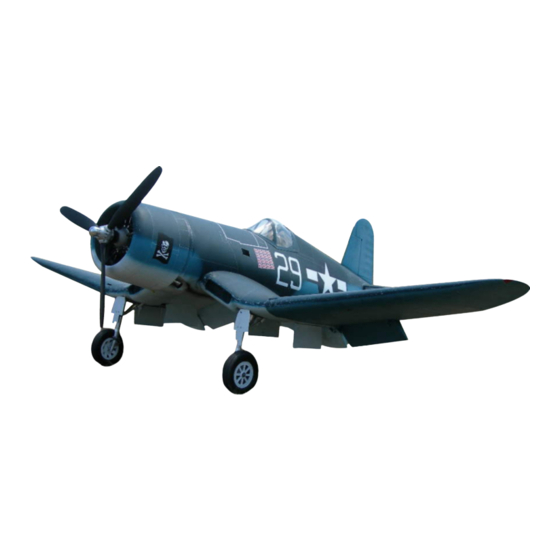
Summary of Contents for Carf-Models F4U-1D Corsair
- Page 2 However, as manufacturers, we at CARF-Models are not in a position to influence the way you build and operate your model, and we have no control over the methods you use to install, operate and maintain the radio control system components.
-
Page 3: Supplementary Safety Notes
DON’T FLY at that time. If you fly with 2.4 GHz technology, please follow the radio manufacturer’s instructions for range checking. Always check range before a flying session! Page 3 Instruction Manual F4U-1D Corsair... - Page 4 If you carefully checked all the points above and followed our advice exactly, you will have a safe and successful first flight - and many hours of pleasure with your CARF-Models F4U-1D Corsair. Please check the important values at the end of this manual for control throws and Center of...
- Page 5 Fuselage and tail planes are a fairly standard design based on the many years of production experience of CARF Models. The hard- ware is complete and well chosen for the task. Much of it is pre-installed in the ARF version. Page 5 Instruction Manual F4U-1D Corsair...
-
Page 6: Getting Started
We recommend to follow this manual closely to avoid time consuming and expensive mistakes. CARF-Models offers the F4U-1D Corsair in 3 different versions. This manual starts at the very beginning of assembling a folding wing kit version (#792000). - Page 7 Clean the wood edges with sand paper, where necessary. Important: After cutting the wood please check all glue joints which appear below. Use epoxy glue and, if needed, some little patches of fiberglass reinforcement. Page 7 Instruction Manual F4U-1D Corsair...
- Page 8 If the mounting rails are not 100% parallel, please use very thin plywood (included in the hardware bag) to slightly pack the mounting areas. Page 8 Instruction Manual F4U-1D Corsair...
- Page 9 CA. Fit the permanent covers with tape and drill 1.5mm holes, which will work perfectly for the supplied 2.2mm sheet metal screws. Check allignment of gear to be parallel in front and side view. Page 9 Instruction Manual F4U-1D Corsair...
- Page 10 After everything works smoothly, you can apply nice epoxy fillets to every glue joint, as some joints have been only tack-glued during the assembly process. Page 10 Instruction Manual F4U-1D Corsair...
- Page 11 The result of your hard work: A giant wheel in a perfectly snug wheel well, covered with tightly fitted gear doors. Page 11 Instruction Manual F4U-1D Corsair...
- Page 12 The hydraulics come with a separate instruction manual, which you please read with great care before you start installing the system into your Corsair. Page 12 Instruction Manual F4U-1D Corsair...
- Page 13 You to center wing should also check the distance edge between the up folded wing stud and Page 13 Instruction Manual F4U-1D Corsair...
- Page 14 If you feel resistance here, you will risk a down lock failure later. Make sure everything operates smoothly and freely! A folding wing is a beautiful scale feature, but it requires technical understanding and careful attention to the mechanical design to operate safely! Page 14 Instruction Manual F4U-1D Corsair...
- Page 15 You should use a depth gauge (any brass tube over the drill bit will do) or a very short drill bit to prevent drilling too deep. Page 15 Instruction Manual F4U-1D Corsair...
- Page 16 Bolt the aluminum hinge on to hinge with the the plywood and glue the plywood wing fold unit, permanently in place, leaving the exactly parallel extended pin as a jig in place. and co-axial! Page 16 Instruction Manual F4U-1D Corsair...
- Page 17 2 mm smaller than the cover. Ready to fill the joints with epoxy/microballon... Note: your kit has M4 bolts and T-nuts in- cluded instead of the self tappers as in the pics! Page 17 Instruction Manual F4U-1D Corsair...
- Page 18 But the function is the same. Congratulations: You have managed to install the wing fold mechanics into your Corsair wing. This was the most complicated task. The remaining building steps should go very straight forward. Page 18 Instruction Manual F4U-1D Corsair...
- Page 19 It still can slide off during flight. Make sure that the bolt is tightened properly and check this before every flight. Page 19 Instruction Manual F4U-1D Corsair...
- Page 20 Mark the hinge post positions to the aileron spar of the outer wing panel and mill 3 slots (3mm wide). Do not yet glue at this point. drawing of hinge Page 20 Instruction Manual F4U-1D Corsair...
- Page 21 Assemble the flap hinges with the 3mm thick flap-side piece and the 2 2mm thick wing-side pieces with an M4 bolt and stop nut. Photo of assembled hinge Page 21 Instruction Manual F4U-1D Corsair...
- Page 22 When all is glued and freely moving, take the hinges apart and take all controls off. Use resin filled with microballon to create nice fillets around the flap hinges. Page 22 Instruction Manual F4U-1D Corsair...
- Page 23 20 mm tube. So you might have to cut the outer one of the front hinges short, as shown on the photo, before you finally glue it in. Page 23 Instruction Manual F4U-1D Corsair...
- Page 24 4 separate channels or matchboxes for the flaps. Locate the position of the pushrod. If necessary grind away any excess glue you used to mount and secure the flap offset hinge. Page 24 Instruction Manual F4U-1D Corsair...
- Page 25 “rattle” on the plate. However, it really is enough to slot the fiberglass surface. Any additional reinforcement of that slot is not necessary. Allow flexing of flap hinges! Page 25 Instruction Manual F4U-1D Corsair...
- Page 26 If necessary, you need to adjust the linkage holes drilled in the spar and mill away some fiberglass material around the control horns. Inner Flap Servo Outer Flap Servo Aileron Servo (install with an extended screwdriver) Page 26 Instruction Manual F4U-1D Corsair...
- Page 27 30 min epoxy. stalled, last the phe- Scuff the glueing surfaces very well nolic washer should and clean from dust with alcohol. be glued with CA. Page 27 Instruction Manual F4U-1D Corsair...
- Page 28 Finally, disassemble the doors and fill all tack-glue joints with 30 min epoxy or resin and microballon to strengthen them. Page 28 Instruction Manual F4U-1D Corsair...
- Page 29 Glue in the plywood rib so that the top surface of the 3mm Process of installing the single rudder hinge post. Take phenolic hinge post is flush with the great care because this is the only one... Page 29 Instruction Manual F4U-1D Corsair...
- Page 30 You will find that the torsion linkage becomes fully defined and solid as soon as both pushrods are installed between torsion rod and servo horn. Page 30 Instruction Manual F4U-1D Corsair...
- Page 31 Mill the slots for the hinge posts into the stab surface’s spar. Shorten the inner hinge post so that it does not interfere with the stab tube. The elevators have to be attached to the Page 31 Instruction Manual F4U-1D Corsair...
- Page 32 Make sure that Next tap these holes M3, the torsion countersink the bolt heads linkage stays in and install the bolts to see the during the whole result of your work. In case joining process. Page 32 Instruction Manual F4U-1D Corsair...
- Page 33 Drill with 3 mm (mark the position carefully and precisely) and then glue in an M3 T-nut Page 33 Instruction Manual F4U-1D Corsair...
-
Page 34: The Front End
CA. Make sure that the top contour of the cowling is perfectly in line with the fuselage’s contour, Page 34 Instruction Manual F4U-1D Corsair... - Page 35 (viewed from the front against the firewall) by 12 mm. 0.5 deg. upthust will be perfect. this and the sligthly nose down cowl, makes it 6 mm to the bottom. Page 35 Instruction Manual F4U-1D Corsair...
- Page 36 NO CIRCUMSTANCES reach a hot engine part. Last but not least, make sure that the ignition unit is mounted as isolated as possible, keep batteries, receiver, servos, switches and power leads as far away as possible. Page 36 Instruction Manual F4U-1D Corsair...
- Page 37 The long extension permanently installed in the center wing can also incorporate a Y-harness to the inner flap servo. For elevator and rudder servos lead extensions can be hard wired or standard extensions of your radio Page 37 Instruction Manual F4U-1D Corsair...
- Page 38 (4 seconds UP and 1 second DOWN). Then program the switch points according to the valve instruction, retract valve close to the DOWN position, gear door valve close to the Page 38 Instruction Manual F4U-1D Corsair...
- Page 39 We recommend to use Baby Oil as hydraulic medium. This is clean, non- toxic, not harmful to the skin, has no Page 39 Instruction Manual F4U-1D Corsair...
- Page 40 You should not need more than 4 bar, though, when the outer wing panels are not mounted, to move the cylinders between their end positions. Cycle the wing fold several times. Make sure that you refill the plastic bladder after every cycle. That’s why we recommend to keep a Page 40 Instruction Manual F4U-1D Corsair...
- Page 41 If the cylinders do not safely reach the end positions, especially in the DOWN position, increase the pressure in the accumulator. If the pump switches on and off in 1-second intervals approximately, you have found the correct operating pressure. Page 41 Instruction Manual F4U-1D Corsair...
- Page 42 Use ZAP canopy glue or 30 min epoxy. It is very important that you tape the canopy on to the fuselage during curing, so that it stays in undistorted shape. Page 42 Instruction Manual F4U-1D Corsair...
- Page 43 Do not assume that a radial engine runs without vibration. A radial engine with a single sided counter balance on the crank shaft does have very noticable vibrations, which seem “softer” than the vibrations of a Page 43 Instruction Manual F4U-1D Corsair...
- Page 44 If you have carefully checked all the points above and followed our advice exactly, you’ll have a safe and successful first flight - and many hours of pleasure with your CARF-Models Corsair. Important Note: NEVER attempt to take off with full power, especially when you use powerful engines like a Moki 250.
-
Page 45: Included Hardware
Hardware bag No1 and the mechani- cal parts of the wing fold system are already installed in the factory. Wing fold system complete (partially installed in ARF planes) fuselage bag wing bag elevator bag rudder bag Page 45 Instruction Manual F4U-1D Corsair...
Need help?
Do you have a question about the F4U-1D Corsair and is the answer not in the manual?
Questions and answers