Chapters
Table of Contents
Troubleshooting

Related Manuals for Psion Teklogix 7527C-G2


Summary of Contents for Psion Teklogix 7527C-G2
-
Page 1: User Manual
WORKABOUT PRO Hand-Held Computer With Windows Mobile 6.1 Classic & Professional (Model No. 7527C-G2 & 7527S-G2) User Manual February 22, 2010 Part No. 8100200.A ISO 9001 Certified Quality Management System... - Page 2 2100 Meadowvale Boulevard, Mississauga, Ontario, Canada L5N 7J9 http:\\www.psionteklogix.com This document and the information it contains is the property of Psion Teklogix Inc., is issued in strict confidence, and is not to be reproduced or copied, in whole or in part, except for the sole purpose of promoting the sale of Psion Teklogix manufactured goods and ser- vices.
- Page 3 Return-To-Factory Warranty Psion Teklogix Inc. provides a return to factory warranty on this product for a period of twelve (12) months in accordance with the Statement of Limited Warranty and Limitation of Liability provided at www.psionteklogix.com/warranty. (If you are not already a member of Teknet and you attempt to view this warranty, you will be asked to register.
-
Page 5: Table Of Contents
ABLE OF ONTENTS Chapter 1: Introduction About This Manual ..............3 Text Conventions . - Page 6 Contents Chapter 3: Get To Know WORKABOUT PRO Features of the WORKABOUT PRO ..........35 The Batteries .
- Page 7 Contents Windows Mobile 6.1 Desktop––Today Screen ......... . . 61 4.2.1 Windows Mobile 6.1 Navigation Bar .
- Page 8 Contents Getting Started............... . .101 PTSI Imager Demo .
- Page 9 Contents App Launch Keys..............124 Buttons Icon .
- Page 10 Contents 6.20.3 Utilities ...............155 6.21 Encryption.
- Page 11 Contents 6.35.3 Radio Features ..............196 6.35.4 User System Setting .
- Page 12 Contents Attaching The Hand Strap .............250 Attaching The Pistol Grip.
- Page 13 Contents 7.22.4 Indicator Does Not Light When Battery Installed ......272 7.23 Quad Docking Station––WA4204-G2 & WA4304-G2 ........273 7.23.1 Quad Docking Station Setup.
- Page 14 Contents 8.5.2 SE1524ER Scanner Specifications..........311 8.5.3 EV15 Imager Specifications .
- Page 15 Contents C.4.2 Setting The Active Preset............C-9 C.4.3 Viewing A Preset.
- Page 16 Contents D.2.20 Micro PDF-417 ............. D-19 Decoded (HHP).
- Page 17 Contents D.3.38 Postal: Japanese ............. D-41 D.3.39 Postal: Kix .
- Page 19 NTRODUCTION 1.1 About This Manual ........3 1.2 Text Conventions .
-
Page 21: Chapter 1: Introduction
Chapter 1: Introduction About This Manual About This Manual This manual describes how to configure, operate and maintain the WORKABOUT PRO (Model Numbers 7527C-G2 and 7527S-G2) hand-held computer. Chapter 1: Introduction provides a basic overview of the WORKABOUT PRO hand-held. -
Page 22: Text Conventions
Note: For a complete list of WORKABOUT PRO specifications, refer to ““Hand-Held Computer Specifications”” on page 287 Model Variants •• WORKABOUT PRO C –– Model 7527C-G2 •• WORKABOUT PRO S –– Model 7527S-G2 Platform •• PXA270M @ 624 MHz, 32 bit RISC CPU ••... -
Page 23: User Interface
Chapter 1: Introduction WORKABOUT PRO Features Operating System •• Microsoft Windows Mobile 6.1 Professional •• Microsoft Windows Mobile 6.1 Classic Multi-Media Chipset •• NVIDIAGoForce 4000 Multi-Media Processor Real-Time Clock •• CPU independent RTC capable of maintaining the system date and time for at least 3 months with a fully charged backup battery User Interface ••... -
Page 24: The Workabout Pro 3 C Hand-Held
Chapter 1: Introduction The WORKABOUT PRO C Hand-Held - GPRS Class B, Multi-Slot Class 12 - EGPRS Class B, Multi-Slot Class 12 •• UMTS/HSDA (via expansion interface) - Triple-Band –– 850/1900/2100 MHz Voice and Data •• Integrated Bluetooth class II, ver 1.2 - Working Range: 16.4 ft.to 32.81 ft. -
Page 25: The Workabout Pro 3 S Hand-Held
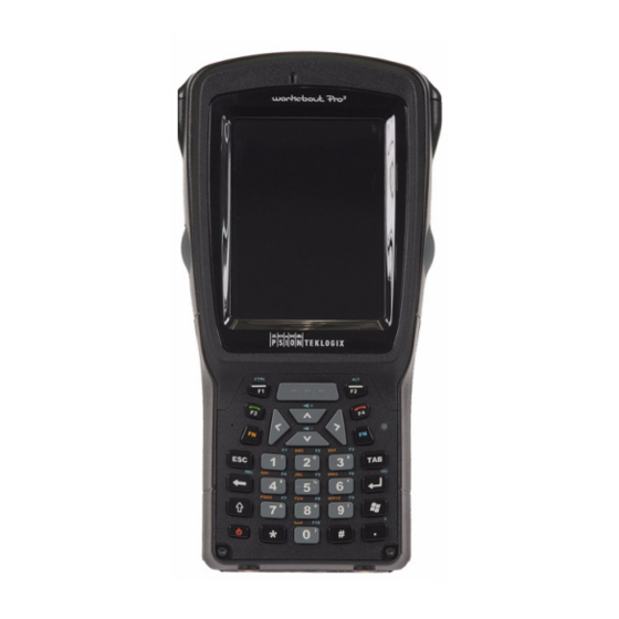
1.3.2 The WORKABOUT PRO S Hand-Held Figure 1.2 WORKABOUT PRO S with QWERTY Keyboard... - Page 26 Chapter 1: Introduction The WORKABOUT PRO S Hand-Held Figure 1.3 WORKABOUT PRO S with Numeric Keyboard Figure 1.4 Phone Labels Send Note: The [Send] and [End] phone keys printed on the hand-held shown in the sample above are useful for units equipped with Windows Mobile 6.1 Professional that sup- port the phone feature.
- Page 27 ASIC HECKOUT 2.1 Preparing the WORKABOUT PRO for Operation ....11 2.1.1 The Main Battery ....... 11 2.1.1.1 Charging the Main Battery .
- Page 28 2.8.3.5 Data Tab ....... 30 2.8.3.6 Bands ....... . . 31 2.9 Resetting the WORKABOUT PRO Hand-Held .
-
Page 29: Chapter 2: Basic Checkout
Lithium-Ion backup battery that can be ordered through Psion Teklogix. The backup battery will supply 5 minutes of continuous power while you install a charged, main battery. -
Page 30: Turning The Workabout Pro 3 On And Off
Chapter 2: Basic Checkout Turning the WORKABOUT PRO On and Off is switched on or off, in a docking station or a cradle. Even when the main battery reaches its Suspend Threshold (refer to ““Suspend Threshold”” on page 167) and the hand- held shuts down, the backup battery will continue to draw a trickle charge from the main battery to protect the data stored in the unit until a charged main battery is installed. -
Page 31: Switching The Unit Off (Suspend)
Chapter 2: Basic Checkout Switching the Unit Off (Suspend) Note: If you are using a docking station or an external power supply, you can insert an uncharged battery, dock the unit and switch it on. To switch on the WORKABOUT PRO ••... -
Page 32: Data Transfer Between The Pc & The Hand-Held
Chapter 2: Basic Checkout Connecting the WORKABOUT PRO to a PC hand-held is in a Standby state. In addition, the radios remain on. You should be aware that because the processor continues to run, Standby mode consumes more power than Suspend mode. -
Page 33: Using Microsoft® Vista
Chapter 2: Basic Checkout Using Microsoft® Vista® 2.4.2 Using Microsoft® Vista® If you have Windows Vista, your WORKABOUT PRO data transfers do not require Active- Sync. To transfer data between your PC and your hand-held: •• Tap on Start>Computer to display the drives. Your WORKABOUT PRO will be visible here. -
Page 34: Setting Up A Ra2041 Radio–-Summit Client Utility
Chapter 2: Basic Checkout Setting Up a RA2041 Radio––Summit Client Utility •• To get instructions about an operation, tap on an option in the Getting Started list. Follow the instructions provided. •• Where applicable, a link to an associated screen is provided.Tap on the link to display the screen and complete your task. -
Page 35: Using The Scu To Connect To The Wlan
Chapter 2: Basic Checkout Using the SCU to Connect to the WLAN If you want to use a particular IP address, tap on Use specific IP address, and type the pre- ferred address. If you tap on the Name Servers tab, you can statically configure the DNS servers; however, if you use DHCP for IP address assignment, DNS is usually supplied by the same server that supplied the IP addresses. - Page 36 Chapter 2: Basic Checkout Using the SCU to Connect to the WLAN •• Tap on the Profile tab. •• Tap on New to define a new profile. •• Type a unique name for your configuration using any alpha-numeric combination to uniquely identify this profile.
- Page 37 Chapter 2: Basic Checkout Using the SCU to Connect to the WLAN To configure encryption: •• Tap on the Encryption drop-down menu, and choose the appropriate type of encryption –– Manual WEP, Auto WEP, WPA PSK, WPA TKIP, WPA2 PSK, WPA2 AES, CCKM TKIP, CKIP Manual or CKIP Auto.
-
Page 38: The Phone (Windows Mobile 6.1 Professional Only)
Chapter 2: Basic Checkout The Phone (Windows Mobile 6.1 Professional Only) The Phone (Windows Mobile 6.1 Professional Only) WORKABOUT PRO s running Windows Mobile 6.1 Professional are equipped with phone capabilities. Note: Remember that you can use the Help feature to find more details about phone options. -
Page 39: Make A Conference Call
Chapter 2: Basic Checkout The Phone Keypad To send a number: •• Use the phone keypad to enter the phone number, and tap on Send to dial the phone number. To end a phone call: •• Tap on End key on the phone keypad. Note: You can also tap on the [End] key on the physical keyboard of the WORKABOUT to end the call providing this key has been activated. - Page 40 Chapter 2: Basic Checkout The Phone Keypad •• In the phone keypad, tap on the Speed Dial button to display the speed dial Phone dialog box. Speed Dial Number This dialog box lists the phone numbers and the speed dial key to which the phone number has been assigned.
- Page 41 Chapter 2: Basic Checkout The Phone Keypad •• In the list, choose a contact for a speed dial. •• Tap on Enter a name, and type a contact name, or tap on a name in the list. A sequential speed dial key is automatically assigned in the Location field. You can tap on the Location drop-down menu and change the auto assignment.
-
Page 42: Send & End Calls Using The Workabout Pro 3 Keyboard
Chapter 2: Basic Checkout Send & End Calls Using the WORKABOUT PRO Keyboard Using the Contact List to Program a Speed Dial •• Tap Contact in the softkey bar at the bottom of the Today screen. •• Tap on the Contact to which you want to assign a speed dial number. ••... - Page 43 Tap on the Experience tab. •• If it’’ s not chosen by default, choose Psion Teklogix Settings in the drop-down menu at the top of the screen. The checkbox next to ‘‘Enable Phone keys (Send and End) in place of the [Tab] and [Esc] keys’’ should be checked automatically. If not, check it and tap on OK.
-
Page 44: Managing Phone Settings
Chapter 2: Basic Checkout Managing Phone Settings 2.8.3 Managing Phone Settings You can adjust phone settings such as the ring type and tone, choose phone services such as barring calls, and you can also determine network selections. There are a number of ways you can access phone settings. -
Page 45: Security Tab
Chapter 2: Basic Checkout Managing Phone Settings 2.8.3.2 Security Tab Tap in the checkbox (add a checkmark) to enable PIN Security. This option allows you to assign a PIN (Personal Identification Number) so that your hand- held is protected from unauthorized use. Your SIM card manufacturer provides the default PIN which you can change in this field. - Page 46 Chapter 2: Basic Checkout Managing Phone Settings Important: If you enter an incorrect PIN, a message is displayed letting you know that you’’ll need to reenter the correct value. You have five chances to enter the correct PIN. If you exceed this number, the SIM will be disabled automatically.
-
Page 47: Services Tab
Chapter 2: Basic Checkout Managing Phone Settings 2.8.3.3 Services Tab The Services tab allows you to customize the behaviour of your phone. You can, for exam- ple, block all incoming calls, tailor to whom your caller ID will be transmitted, set up call forwarding and so on. -
Page 48: Network Tab
Chapter 2: Basic Checkout Managing Phone Settings 2.8.3.4 Network Tab This dialog box identifies your current network, and allows you to view available networks and determine the order in which other preferred networks will be accessed if the current one is unavailable.You can also specify manual or automatic network changes, and you can add a network. -
Page 49: Resetting The Workabout Pro
Chapter 2: Basic Checkout Resetting the WORKABOUT PRO Hand-Held 2.8.3.6 Bands By default, all frequency bands are enabled. Bands should not be disabled without knowl- edge about which bands are used by your network; an incorrect setting will prevent the WWAN modem from finding the network. -
Page 50: Performing A Cold Reset To The Windows Mobile 6.1 Os
Chapter 2: Basic Checkout Performing a Cold Reset to the Windows Mobile 6.1 OS 2.9.2 Performing a Cold Reset to the Windows Mobile 6.1 OS A cold reset in Windows Mobile is almost identical to a warm reset, except that some lower level hardware (PCon) is also reset before the operating system boots. -
Page 51: Features Of The Workabout Pro
WORKABOUT PRO 3.1 Features of the WORKABOUT PRO ......35 3.2 The Batteries ........37 3.2.2 Removing the Battery Pack . - Page 52 3.10.1 Pairing a Bluetooth Device ......52 3.11 Inserting the SD/MMC Card and SIM Card ..... . 55 3.11.1 Inserting and Removing the Card .
-
Page 53: Features Of The Workabout Pro
Chapter 3: Get To Know WORKABOUT PRO Features of the WORKABOUT PRO Features of the WORKABOUT PRO Figure 3.1 Front of WORKABOUT PRO Speaker (Light Emitting Diode) Microphone Port WORKABOUT PRO with Windows Mobile 6.1 User Manual... - Page 54 Chapter 3: Get To Know WORKABOUT PRO Features of the WORKABOUT PRO Figure 3.2 Back of WORKABOUT PRO End Cap Stylus (pointing tool) Back Cover Battery Cover Battery Latches WORKABOUT PRO with Windows Mobile 6.1 User Manual...
-
Page 55: The Batteries
Chapter 3: Get To Know WORKABOUT PRO The Batteries Figure 3.3 Ports Tether Port Beeper Port Low Insertion Force Port (LIF) DC IN Socket The Batteries The hand-held operates with a Lithium-Ion battery pack. Preparing the unit for operation re- quires that a battery pack be charged and installed in the WORKABOUT PRO Two levels of battery packs are available for the WORKABOUT PRO ••... -
Page 56: Removing The Battery Pack
Chapter 3: Get To Know WORKABOUT PRO Removing the Battery Pack 3.2.2 Removing the Battery Pack Important: Always switch the unit off before opening the battery cover to remove the battery. When the cover is removed, a power-off switch is automatically acti- vated and the unit power is switched off;... -
Page 57: Charging The Battery
Chapter 3: Get To Know WORKABOUT PRO Charging the Battery Important: Before opening the battery cover on your WORKABOUT PRO to remove the battery, you must turn press the Power button to turn off the hand-held. 3.2.4 Charging the Battery Batteries shipped from the factory are charged to approximately 40% of capacity. -
Page 58: Switching The Hand-Held On And Off
Chapter 3: Get To Know WORKABOUT PRO Switching the Hand-Held On and Off It can take up to 4 hours to charge a battery. The WORKABOUT PRO intelligent charging system protects the battery from over-charging by terminating the charge process when the battery is at maximum capacity. -
Page 59: The Keyboards
Chapter 3: Get To Know WORKABOUT PRO The Keyboards The Keyboards 3.4.1 The WORKABOUT PRO Keyboard This hand-held computer is available in two models, C and S. The WORKABOUT PRO model is available with an alphanumeric keyboard; the WORKABOUT PRO S model is available with either a QWERTY or numeric keyboard. -
Page 60: Locking Modifier Keys
Chapter 3: Get To Know WORKABOUT PRO Modifier Keys •• Tap in the check box next to Show modifier key state to display the shift-state indicator icon. Figure 3.4 Shift-State Indicator Icon Shift-State Indicator Icon replaces Soft Keyboard Icon. Soft Keyboard Icon 3.4.2.2 Locking Modifier Keys Note: The locking behaviour of the modifier keys can be changed so that, for example, pressing a modifier key once will lock the key ‘‘on’’. -
Page 61: The Keys
Chapter 3: Get To Know WORKABOUT PRO The Keys 3.4.3 The Keys The [SHIFT] Key The [SHIFT] key is used to display uppercase alpha characters and provide access to the symbols above the numeric keys. You can lock this key ‘‘on’’ so that when you press an alpha key, an upper case character is displayed. - Page 62 Chapter 3: Get To Know WORKABOUT PRO The Keys The [SPACE] Key Pressing this key inserts a blank space between characters. In a Windows dialog box, press- ing the [SPACE] key enables or disables a checkbox. On the WORKABOUT PRO numeric keyboard, this key is accessed by key combination ––...
-
Page 63: Alpha Keyboard –- Accessing Keys
Chapter 3: Get To Know WORKABOUT PRO Alpha Keyboard –– Accessing Keys To access macro key [M1], press [FN/ORANGE] [1]. To access macro key [M2], press [FN/ORANGE] [2], and so on. 3.4.4 Alpha Keyboard –– Accessing Keys The alpha and numeric keys on WORKABOUT PRO C units are directly accessible from the keyboard ––... -
Page 64: Creating Uppercase Letters
Chapter 3: Get To Know WORKABOUT PRO Numeric Keyboard –– Accessing Alpha Keys Note: To choose the second, third or fourth alpha character assigned to a numeric key, you may want to lock the [FN/ORANGE] key ‘‘on’’. By default, the [FN/ORANGE] key is locked ‘‘on’’... -
Page 65: The Keypad Backlight
Chapter 3: Get To Know WORKABOUT PRO The Keypad Backlight 3.4.7 The Keypad Backlight The intensity of the keypad backlight can be configured using the Backlight icon accessed by tapping on Start>Settings. Refer to ““Backlight”” on page 147 for details about this option. -
Page 66: Screen Orientation
Chapter 3: Get To Know WORKABOUT PRO Screen Orientation •• Tap on the Screen icon to display the Alignment tab. •• Tap on the Align Screen button, and follow the directions on the screen to align (cali- brate) the screen. Note: This window provides two additional tabs: ClearType and Text Size. -
Page 67: Indicators
Chapter 3: Get To Know WORKABOUT PRO Indicators •• Tap on the Screen icon. •• In the General tab, tap on the orientation that best suits the way in which you use your WORKABOUT PRO Indicators The WORKABOUT PRO uses an LED (Light Emitting Diode), onscreen messages and audio tones to indicate the various conditions of the hand-held, the batteries, the scans and so on. -
Page 68: Adjusting Speaker Volume
Chapter 3: Get To Know WORKABOUT PRO Adjusting Speaker Volume field or the battery is low. To specify how you want your WORKABOUT PRO to respond under various conditions, refer to ““Sound & Notifications”” on page 143. The volume can be adjusted using the [UP ARROW] and [DOWN ARROW]. The increase volume key is labelled with a plus symbol and the decrease volume key is la-... -
Page 69: Storing Batteries
Chapter 3: Get To Know WORKABOUT PRO Storing Batteries •• When the hand-held is switched off, it goes into a low-power, suspend state but contin- ues to draw a small amount of power from the battery. This should not be an issue unless the unit is left in suspend state for more than a week——for long-term storage, the battery should be removed from the unit. -
Page 70: Bluetooth Radio
Chapter 3: Get To Know WORKABOUT PRO Bluetooth Radio When a WORKABOUT PRO is properly inserted in a docking station, a dock icon is dis- played in the navigation bar at the top of the screen. The unit also detects the presence of the Ethernet network. - Page 71 Chapter 3: Get To Know WORKABOUT PRO Pairing a Bluetooth Device •• Choose the Devices tab, and tap on the Scan button to scan for devices in the area. •• When the scan is complete, tap and hold the stylus on the device to which you want to pair.
- Page 72 Chapter 3: Get To Know WORKABOUT PRO Pairing a Bluetooth Device After entering the device PIN, the Services dialog appears with a list of services available for that device. •• Click in the checkbox to the left of the service to activate it. ••...
-
Page 73: Inserting The Sd/Mmc Card And Sim Card
Chapter 3: Get To Know WORKABOUT PRO Inserting the SD/MMC Card and SIM Card •• Serial is used for simple serial port communication. •• ActiveSync is for ActiveSync-over-Bluetooth. •• Scanner is used to create a seamless connection between the incoming Bluetooth bar code and the WORKABOUT PRO Once you’’ve completed the information: ••... - Page 74 Chapter 3: Get To Know WORKABOUT PRO Inserting and Removing the Card •• On a WORKABOUT PRO C, pull the hinged door down as the arrow icon on the door indicates. •• On a WORKABOUT PRO S, pull the metal door upward to expose the SD/MMC slots.
-
Page 75: General Maintenance
Chapter 3: Get To Know WORKABOUT PRO General Maintenance 3.12 General Maintenance 3.12.1 Caring for the Touchscreen The top of the touchscreen is a thin, flexible polyester plastic sheet with a conductive coating on the inside. The polyester can be permanently damaged by harsh chemicals and is susceptible to abrasions and scratches. -
Page 77: Chapter 4: Working With Windows Mobile
ORKING INDOWS OBILE 4.1 Navigating in Windows Mobile 6.1 and Applications ....61 4.1.1 Navigating Using a Touchscreen and Stylus ....61 4.2 Windows Mobile 6.1 Desktop––Today Screen . - Page 78 4.10.3 Block Recognizer and Letter Recognizer ....85 WORKABOUT PRO with Windows Mobile 6.1 User Manual...
-
Page 79: Navigating In Windows Mobile 6.1 And Applications
Chapter 4: Working With Windows Mobile 6.1 Navigating in Windows Mobile 6.1 and Applications Navigating in Windows Mobile 6.1 and Applications Graphic user interfaces like Windows Mobile 6.1 for portable devices or desktop Windows (2000, XP, etc.) utilize ‘‘point and click’’ navigation. On the WORKABOUT PRO , this is accomplished using a touchscreen and stylus rather than a mouse. -
Page 80: Windows Mobile 6.1 Navigation Bar
Chapter 4: Working With Windows Mobile 6.1 Windows Mobile 6.1 Navigation Bar The Today screen displays all your important information––tasks, unread e-mails and upcoming appointments––all in one place. The Start menu provides access to everything else you’’ll need. 4.2.1 Windows Mobile 6.1 Navigation Bar The navigation bar along the top of the screen provides icons that, when tapped, open their associated programs. - Page 81 Chapter 4: Working With Windows Mobile 6.1 Windows Mobile 6.1 Navigation Bar Connectivity The Connectivity hotkey provides a shortcut to the Connections tab in the Settings window. This tab provides access to Bluetooth, network, network card and internet connection setups. Phone Settings If you’’re hand-held is running Windows Mobile 6.1 Professional, it is equipped with a phone option.
-
Page 82: Volume Control
Chapter 4: Working With Windows Mobile 6.1 Windows Mobile 6.1 Navigation Bar Volume Control Tapping on this icon displays a sliding tab that allows you to adjust the speaker volume or turn the speaker on and off. On units running Windows Mobile 6.1 Professional, two volume adjustments are provided –– one for the speaker volume and the other for the phone dialer volume. -
Page 83: Today’'S Date, Clock And Alarm
Chapter 4: Working With Windows Mobile 6.1 Today’’ s Date, Clock and Alarm 4.2.2 Today’’ s Date, Clock and Alarm This option displays the current date. If you need to adjust the date or set an alarm: •• In the Today screen, tap on today’’s date. The Clock &... - Page 84 Chapter 4: Working With Windows Mobile 6.1 Today’’ s Date, Clock and Alarm Alarms Tab To set an alarm: •• Tap on the Alarms tab. You can set a maximum of three alarms. •• Tap in the checkbox to enable an alarm. ••...
-
Page 85: Ownership Information
Chapter 4: Working With Windows Mobile 6.1 Ownership Information •• To set the time, in the time field below the clock, tap on the hour to highlight it, and type the hour at which you want the alarm to ring. To set the minutes, highlight the min- utes, and type the appropriate minutes, or You can also assign the alarm activation time using the clock graphic. -
Page 86: E-Mail Notification
Chapter 4: Working With Windows Mobile 6.1 E-mail Notification 4.2.4 E-mail Notification If you have any e-mail, it will be indicated in the Today desktop screen. To view your e-mail, tap on the E-mail Notification option. Refer to ““Messaging”” on page 111 for details about setting up your Inbox. 4.2.5 Task Notification Tasks lets you create lists of entries representing your responsibilities, upcoming projects,... - Page 87 Chapter 4: Working With Windows Mobile 6.1 Task Notification Editing a Task •• Tap on a task in the task list to highlight it. Tap Edit in the softkey bar to display a detailed task screen where you can define task characteristics. Figure 4.1 Task Details Screen Each of the nine items in this screen, when tapped, displays a drop-down menu where you can choose from a list of options.
-
Page 88: Calendar Of Upcoming Appointments
Chapter 4: Working With Windows Mobile 6.1 Calendar of Upcoming Appointments You can choose All Tasks, Recently Viewed, No Categories, Active Tasks or Completed Tasks. The tasks are displayed on the screen according to the preference you chose. 4.2.6 Calendar of Upcoming Appointments This option is used to map out all your upcoming appointments, meetings and so on in the weeks, months and years ahead. -
Page 89: Adding Reminders
Chapter 4: Working With Windows Mobile 6.1 Calendar of Upcoming Appointments Figure 4.2 Appointment Detail Screen •• In the Subject field, name the appointment. •• Complete the remaining fields to reflect your appointment details. Note: Refer to ““Adding Reminders”” on page 71 for details. Refer to ““Using Categories”” on page 72 for information about this option. -
Page 90: Using Categories
Chapter 4: Working With Windows Mobile 6.1 Calendar of Upcoming Appointments •• In the second Reminder field, tap on the number in the field to display a drop-down menu where you can define a numeric value of 1, 5, 10, 15, 30. Tap on minute(s) to display a drop-down menu from which you can choose the time unit for your reminder––... -
Page 91: Deleting Appointments
Chapter 4: Working With Windows Mobile 6.1 Calendar of Upcoming Appointments •• Tap the Categories field to display the Categories screen. •• Tap in the checkbox next to the category to which you want to assign the appointment. •• Tap OK. Your appointment is assigned to the category or categories you chose. Note: You can create a new category by tapping on New in the softkey bar at the bottom of the screen. -
Page 92: Start Menu
Chapter 4: Working With Windows Mobile 6.1 Start Menu Start Menu To display the Start menu: •• Tap on the Start button in the upper-left corner of the Navigation Bar. Start Button Navigation Bar Custom-chosen programs Most recently used programs Windows Mobile command centre ••... -
Page 93: Managing Files And Folders
Chapter 4: Working With Windows Mobile 6.1 Managing Files and Folders •• In the Personal tab, tap on the Menus icon. •• Tap the checkboxes next to the items you would like to appear in your Start menu. When you’’ve finished your selections, tap on OK. Managing Files and Folders Windows Mobile 6.1 files are stored in folders and sub-folders that are accessible with File Explorer. -
Page 94: Creating A New Folder
Chapter 4: Working With Windows Mobile 6.1 Creating a New Folder 4.4.1 Creating a New Folder •• Tap Start>Programs>File Explorer. •• Tap Menu>New Folder in the softkey bar at the bottom of the screen. •• Use the WORKABOUT PRO keyboard or the soft keyboard to assign a name to the folder. -
Page 95: Using Menus
Chapter 4: Working With Windows Mobile 6.1 Using Menus Using Menus In Windows Mobile 6.1 Classic and Professional, the menu is located in the softkey bar at the bottom of the screen. Softkey Bar Menu To execute a command: •• Tap on Menu to display the commands associated with it, and then tap on the command you want to execute. -
Page 96: The Softkey Bar
Chapter 4: Working With Windows Mobile 6.1 The Softkey Bar The Softkey Bar The WORKABOUT PRO is equipped with a softkey bar at the bottom of the screen. It dis- plays softkeys that allow you to access menus and commands. It also displays the soft keyboard icon. - Page 97 Chapter 4: Working With Windows Mobile 6.1 The Softkey Bar •• Tap on Start>Settings>Buttons>One Shots. Tap in the checkbox next to Show modi- fier key state, to replace the soft keyboard icon with the shift-state indicator icon. Shift-state indicator icon When a modifier key is pressed, it is displayed in the shift-state indicator icon.
-
Page 98: Programs–-Using Applications
Chapter 4: Working With Windows Mobile 6.1 Programs––Using Applications Programs––Using Applications •• Tap Start>Programs to display the programs installed on your WORKABOUT PRO Figure 4.3 Program Screen Icons Opening an Application •• Tap on an icon in this screen to launch the associated program. Minimizing an Application ••... - Page 99 Chapter 4: Working With Windows Mobile 6.1 Programs––Using Applications •• Tap on Start>Settings. Tap on the System tab and then the Task Manager icon –– the Task Manager screen is opened. This applet provides a number of options to manage your opened applications. ••...
-
Page 100: Settings
Chapter 4: Working With Windows Mobile 6.1 Settings Settings •• Tap Start>Settings to display the setting options for your hand-held. Figure 4.4 Settings Icons Settings are divided into three tabs––Personal, System and Connections. Refer to Chapter 6: ““Settings”” for details about the options available to you. Help Tapping on the Start>Help displays a screen of help topics that are content-specific;... -
Page 101: Entering Text
Chapter 4: Working With Windows Mobile 6.1 Entering Text 4.10 Entering Text Note: For additional information about tailoring text entry using the soft keyboard, the transcriber, the block recognizer and the letter recognizer, refer to ““Input”” on page 135. You can enter text using either the soft keyboard or the WORKABOUT PRO keyboard. -
Page 102: The Transcriber
Chapter 4: Working With Windows Mobile 6.1 The Transcriber 4.10.2 The Transcriber To access the Transcriber, with your document opened: •• Tap on the arrow next to the keyboard icon, and choose Transcriber from the pop-up menu. •• Review the introductory screen. It provides some shortcut symbols you can draw on your screen to work with the Transcriber. -
Page 103: Block Recognizer And Letter Recognizer
Chapter 4: Working With Windows Mobile 6.1 Block Recognizer and Letter Recognizer Press and hold the stylus on the selected text to display a pop-up menu. Choose Cut, Copy, Paste or Clear (delete). Note: You can also use the softkey bar tools or the shortcuts listed in the introductory screen to help you edit a document within the Transcriber. -
Page 104: Letter Recognizer
Chapter 4: Working With Windows Mobile 6.1 Block Recognizer and Letter Recognizer •• To create an uppercase character, draw a line straight up the ‘‘abc’’ panel. •• Use the Recognizer Icon Bar to move around the screen, add spaces, special characters, and so on. - Page 105 ROGRAMS 5.1 Programs ........89 5.2 Games .
- Page 106 5.12.3 Deleting a Photo ......109 5.12.4 Editing a Photo....... 109 5.12.5 Creating a Slide Show .
-
Page 107: Chapter 5: Programs
Chapter 5: Programs Programs Programs The Programs menu provides access to all the applications available on your hand-held. •• Tap on Start>Programs to display this screen. Tapping on an icon in this screen launches the associated applet. Figure 5.1 Programs Tabs Games Your WORKABOUT PRO is equipped with a few standard games ––... -
Page 108: Synchronization
Chapter 5: Programs Synchronization running ActiveSync on the PC, you can view WORKABOUT PRO files, drag and drop files between the hand-held and the PC, connect to the Internet, and so on. If you need help installing ActiveSync, go to the website below and navigate to the Active- Sync download information: http://go.microsoft.com/fwlink/?LinkId=147001 5.3.1... -
Page 109: Workbook Components
Chapter 5: Programs Excel Mobile In addition to providing the tools to manipulate text and numeric values like statistics, per- centages, using formulas that perform calculations, and so on, this program can also include graphics such as pie charts. Excel Mobile allows you to copy Excel workbooks from your PC onto your WORKABOUT and update them while you’’re away from your desk. -
Page 110: Onenote Mobile
Chapter 5: Programs OneNote Mobile 5.5.2 OneNote Mobile You can use OneNote Mobile to take notes wherever you are and then synchronize your notes with a notebook section in the OneNote version on your PC. For example, you can: •• Snap pictures of business cards on your WORKABOUT PRO and then bring them into OneNote on your PC. -
Page 111: Creating A Note
Chapter 5: Programs OneNote Mobile When a connection is established between the WORKABOUT PRO and your PC, Active- Sync displays a New Partnership screen. •• Choose Standard partnership, and tap on Next. •• To share information between OneNote Mobile and Office OneNote 2007 on your PC, tap Synchronize with this desktop computer, and then tap on Next. - Page 112 Chapter 5: Programs OneNote Mobile If this is not the case, tap on Start>Programs>Office Mobile icon. Tap on the OneNote Mobile icon. •• Tap on New to create a note page. Begin typing. •• When you complete your note, tap on Done. Note: Remember that you can tap on the Menu softkey to Undo typing, add Formats (Bold, Italic, Underline, Strikethrough), include Lists (Numbered, Bulleted, Clear) WORKABOUT PRO...
- Page 113 Chapter 5: Programs OneNote Mobile Using the OneNote Menu Tapping on Menu displays a list of options to help you work with the OneNote Mobile applet. •• Undo, Redo, Cut, Copy and Paste: These commands operate in the same way as they do in any Windows Office application.
- Page 114 Chapter 5: Programs OneNote Mobile Press [ENTER] to snap a photo that is automatically inserted into your note. •• Insert Picture: Tapping on this command automatically displays your My Pictures folder where you can tap on an existing picture to insert it into your note. WORKABOUT PRO with Windows Mobile 6.1 User Manual...
- Page 115 Chapter 5: Programs OneNote Mobile •• Insert Recording: When you tap on this command, a recording panel is displayed. Cancel Save Play Stop Record Tap on the Record button to record your message. Tap on Stop when you’’ve completed your message. Tap on Play to listen to your voice message.
-
Page 116: Word Mobile
Chapter 5: Programs Word Mobile •• In Microsoft ActiveSync on your PC, choose Sync. On your WORKABOUT PRO , tap on Start>ActiveSync, and then tap on Sync. During synchronization, the notes you created on your WORKABOUT PRO are copied to a new Office OneNote 2007 notebook called OneNote Mobile on your PC. -
Page 117: Data Entry Modes
Chapter 5: Programs Word Mobile If you’’ve already create a Word Mobile document, it will be listed in the Word Mobile window. •• Tap on New in the softkey bar to create a new Word document. Using Word Mobile Help If you need help using this application, you can review the instructions in the associated help files. -
Page 118: Powerpoint Mobile
Chapter 5: Programs PowerPoint Mobile Important: To avoid translation problems, you can work on copies of .doc files. In addi- tion, keep in mind that you can use the Terminal Services Client program to log onto a desktop PC that is also running Terminal Services, and then you can use any program on your PC, including Microsoft Word (rather than Word Mobile). -
Page 119: File Explorer
Chapter 5: Programs File Explorer •• Tap on the Settings button to display the Scanner Settings dialog box. Use this dialog box to tailor the scanner settings for your hand-held. •• Tap on the Scan button to test the scanner. Important: For details about the Scanner Settings, refer toAppendix D: ““Bar Code Settings””. -
Page 120: Internet Sharing
Chapter 5: Programs Internet Sharing 5.10 Internet Sharing This option allows you to use your WORKABOUT PRO to connect your PC to the Inter- net. Before you can use Internet Sharing, you must make certain that you have established a data connection on your WORKABOUT PRO 5.10.1 Creating an Internet Connection Follow the steps in this section only if you have not already setup an Internet connection. -
Page 121: Notes
Chapter 5: Programs Notes •• On your WORKABOUT PRO , tap Start>Programs>Internet Sharing. •• Choose the PC Connection type––USB or Bluetooth. •• Choose the network connection that the WORKABOUT PRO should use to connect to the Internet. •• Tap Connect. It takes approximately 30 seconds to establish a connection. (If you are prompted to turn on Bluetooth, tap Yes.) If your are using a Bluetooth connection, execute the following steps on your PC: ••... -
Page 122: Creating A Note
Chapter 5: Programs Creating a Note •• If a blank Note like the sample screen here is not displayed, tap on New in the softkey bar. 5.11.1 Creating a Note •• Choose an entry mode for your note. To enter text with the soft keyboard, Transcriber or the Block or Letter Recognizer, tap the stylus on the arrow to the right on the soft keyboard icon to choose your text input method. - Page 123 Chapter 5: Programs Converting Handwritten Notes to Text •• Tap on the pen tool and compose a note using your stylus. •• Tap on Menu>Tools>Recognize. The text in the note is converted from handwritten to printed text. Note: To convert only a specific portion of your handwritten note into printed type, tap the stylus just before the first letter of the text, pause for a second, and then drag your stylus across the text you want to select.
-
Page 124: Renaming A Note
Chapter 5: Programs Renaming a Note •• In the pop-up menu, choose Alternative to display a list of possible alternatives to the incorrectly converted word. Your handwritten version is displayed along the top of the menu. Figure 5.2 Incorrect Conversions ••... - Page 125 Chapter 5: Programs Recording Notes •• Tap on Menu>View Recording Toolbar. Volume Skip to end Skip to beginning Record Stop Play Progress Indicator •• Tap on the Record button––a beep alerts you that your device is now ready to record. ••...
-
Page 126: Synchronizing A Note
Chapter 5: Programs Synchronizing a Note 5.11.5 Synchronizing a Note Like Tasks, Contacts and so on, the Notes program can be synchronized with Outlook on your PC. In this way, all notes, recordings and drawings created in the Notes program are copied to your PC and can be edited in Outlook’’... -
Page 127: Opening A Photo
Chapter 5: Programs Opening a Photo 5.12.2 Opening a Photo •• Tap on Start>Programs>Pictures & Videos. You’’ll see a thumbnail of your photos. Note: If you’’ve stored your photos on a storage card, you’’ll need to tap on the storage card icon to display your photos. -
Page 128: Internet Explorer
Chapter 5: Programs Internet Explorer •• To display the slide show tool bar, tap anywhere on the photo. Pause Previous Play Next Flip View Close 5.13 Internet Explorer You can connect to Internet Explorer in two ways: by connecting the WORKABOUT PRO directly to the Internet or by connecting through your PC while the hand-held is attached via ActiveSync (see ““ActiveSync®””... -
Page 129: Messaging
Chapter 5: Programs Messaging •• Tap on Start>Programs>Internet Explorer to open Internet Explorer. If Internet Explorer is also from the Today screen, tap on Start>Internet Explorer. •• Tap on the address bar –– the field near the top of the screen where URLs are entered –– to highlight the current URL. -
Page 130: Synchronizing E-Mail With Outlook
Chapter 5: Programs Synchronizing E-mail with Outlook to synchronize additional folders. The folders and messages you move are mirrored on the server. For POP3 accounts, if you move e-mail messages to a folder you create, the link between the messages on the WORKABOUT PRO and the copies on the mail server are broken. -
Page 131: Changing Synchronization Settings
Chapter 5: Programs Changing Synchronization Settings Once you check E-mail for synchronization, Outlook e-mail messages are synchronized as part of the general synchronization process. The next time you synchronize with Active- Sync, the e-mail in Outlook on your PC will be transferred to the Messaging program on your WORKABOUT PRO 5.14.3 Changing Synchronization Settings ••... -
Page 132: Remote Desktop Mobile
Chapter 5: Programs Remote Desktop Mobile •• Add a checkmark next to the folders in this screen that you want to synchronize with your WORKABOUT PRO , and tap on OK. The E-mail Synchronization screen is displayed again. •• If you want to accept file attachments, add a check mark next to Include file attach- ments. -
Page 133: Summit Client Utility (Scu)
Chapter 5: Programs Summit Client Utility (SCU) 5.16 Summit Client Utility (SCU) The SCU provides the utilities you will need to configure the Summit 802.11g Compact Flash radio module, model number RA2041 so that it can communicate through a wireless LAN network effectively and securely. -
Page 134: Task Manager
Chapter 5: Programs Task Manager 5.18 Task Manager The Task Manager lists all running tasks (applications) or processes. This applet provides a number of options to manage these. Refer to ““Task Manager”” on page 171 for details. 5.19 Tasks This program helps you stay ahead of your schedule by managing your tasks, appointments, and so on. - Page 135 ETTINGS 6.1 Settings .........123 6.2 Personal Settings .
- Page 136 6.15 About Device........147 6.16 Backlight .
- Page 137 6.28 Regional Settings ........169 6.29 Remove Programs........170 6.30 Screen Icon .
- Page 138 6.39.2.1 Discovering and Removing Devices ....204 6.39.2.2 Filtering By Class of Device (COD) ....205 6.39.2.3 Device Pop-up Menu .
- Page 139 6.44.5.1 Data Connection Configuration ....232 6.44.5.2 Security Configuration..... . .235 6.44.5.3 Network Configuration .
-
Page 141: Chapter 6: Settings
Chapter 6: Settings Settings Settings The Settings screen is divided into three tabs –– Personal, System and Connections. Note: Keep in mind that the Phone applet is only available when your hand-held is equipped with Windows Mobile 6.1 Professional. •• Tap on Start>Settings to display this screen. -
Page 142: App Launch Keys
Chapter 6: Settings App Launch Keys App Launch Keys This icon allows you to map a key to an application so that you can then launch the applica- tion from a single key-press. To assign an application key: •• Tap the Add button. ••... - Page 143 Chapter 6: Settings App Launch Keys through the information in your hand-held until you locate the application you want to launch. •• Once you’’ve selected the file you want to map, tap on OK. The cursor moves to the Data field. You can use this field if you need to define special pa- rameters to your application launch key.
-
Page 144: Buttons Icon
Chapter 6: Settings Buttons Icon Buttons Icon •• Tap on this icon to display your options. Note: The ‘‘Program Buttons’’ option is not available on this unit. 6.4.1 Up/Down Control Sliding the Delay before first repeat bar to the left decreases the delay between key repeats while sliding the bar to the right increases the repeat delay time. -
Page 145: One Shots
Chapter 6: Settings One Shots 6.4.2 One Shots The options in this tab allows you to determine how modifier keys on your WORKABOUT behave. For each modifier key––[ALT], [SHIFT], [CTRL], [FN/ORANGE] and [FN/BLUE] –– you have the following options in the drop-down menu: Lock, OneShot, and OneShot/Lock. -
Page 146: Keyboard Macro Keys
Chapter 6: Settings Keyboard Macro Keys replaces the soft keyboard icon in the softkey bar at the bottom of the screen. When a mod- ifier key is pressed, a square in this icon is highlighted. A ‘‘locked’’ modifier key is displayed in the shift-state indicator icon with a black frame around it. - Page 147 Chapter 6: Settings Keyboard Macro Keys A Record Macro screen is displayed. •• Type the macro sequence you want to assign to the Macro key. You can type text and numbers, and you can program the function of special keys into a macro. ••...
-
Page 148: Unicode Mapping
Chapter 6: Settings Unicode Mapping 6.4.4 Unicode Mapping •• Tap on the Unicode Mapping tab to display this screen. The Unicode Mapping tab is used to map combinations of virtual key values and [CTRL] and [SHIFT] states to Unicode™™ values. This tab shows the configured Unicode character along with the Unicode value. -
Page 149: Scancode Remapping
Chapter 6: Settings Scancode Remapping •• Tap on the Add/Change button. •• Highlight a value in the Unicode mapping list. •• Position the cursor in the Unicode Mapping field, and type a Unicode value for the highlighted key. Note: To add a shifted state––[SHIFT] and/or [CTRL], tap on the checkbox next to ‘‘SHIFT Pressed’’... - Page 150 Chapter 6: Settings Scancode Remapping presses that occur when the [FN/ORANGE] modifier is on. The default mappings of these scancodes can be overwritten for each of these three tables using Scancode Remapping. The first column in the Scancode Remapping tab displays the Scancodes in hexidecimal. If the scancode is remapped to a virtual key, that virtual key is displayed in the next column la- belled ‘‘V-Key’’.
- Page 151 Chapter 6: Settings Scancode Remapping The Remap Scancode dialog box is displayed. •• Type the scan code in hexidecimal in the field labelled Scancode. Note: The ‘‘Label’’ field displays the default function of the scancode you are remapping. Virtual Key, Function And Macro The radio buttons at the bottom of the dialog box allow you to define to what the scan code will be remapped to: Virtual Key, Function or Macro.
-
Page 152: Lock Sequence
Chapter 6: Settings Lock Sequence Removing A Remap •• In the Scancode Remapping tab, highlight the scancode you want to delete, and tap on the Remove button. •• Tap on OK. 6.4.6 Lock Sequence The Lock Sequence tab allows you to lock the hand-held keyboard to prevent keys from being pressed accidentally when, for example, the unit is inserted in a holster. -
Page 153: Input
Chapter 6: Settings Input A locked keyboard icon is displayed in the softkey bar when the keyboard is locked. Locked Keyboard Icon •• Type the key sequence to unlock the keyboard. Input The Input applet provides access to text input options you can use to tailor the soft keyboard, block recognizer, letter recognizer and transcriber along with voice recording options. -
Page 154: Keyboard Options
Chapter 6: Settings Input Method Tab Block Recognizer Block Recognizer teaches you how to conform your handwriting to what the hand-held can recognize. Important: Refer to ““Block Recognizer and Letter Recognizer”” on page 85 for additional details. Keyboard Options This screen is displayed when you choose Keyboard in the Input method drop-down menu. You can use it to customize the soft keyboard. - Page 155 Chapter 6: Settings Input Method Tab Figure 6.2 Letter Recognizer Quick Settings These options allow the Letter Recognizer to better interpret any specialized strokes and accents you may wish to use. Transcriber Options Note: Before you can display the Options for Transcriber, you need to select Transcriber as the active input method.
- Page 156 Chapter 6: Settings Input Method Tab Inking In the Inking tab, you are presented with a number of options. Recognition Delay allows you to determine the time delay between writing something on the Transcriber screen and its recognition into printed text. Enabling Add space after automatically adds a space after each word you write.
-
Page 157: Options–-Additional Choices
Chapter 6: Settings Options––Additional Choices 6.5.1.1 Word Completion This tab speeds the writing process regardless of the input method chosen. When you begin entering a word, this option displays what it assumes is the complete word, saving you having to type the word in its entirety. You can also tailor how and when you want word sug- gestions made. -
Page 158: Lock
It is critical that you store your password in a safe place. If you forget it, a ‘‘clean start’’ must be performed by certified Psion Teklogix personnel. A clean start returns the hand-held to factory settings. Only the data stored in a CF or SD memory card are preserved. -
Page 159: Menus
Chapter 6: Settings Menus Menus •• Tap on Start>Settings>Menu icon to display options to help customise menus. 6.7.1 Start Menu Tab This tab allows you to define the items that will be listed in your Start menu. •• In the Start Menu dialog box, tap on the items you want to appear in your Start menu. The checked items will be listed in your Start menu. -
Page 160: Microphone
Chapter 6: Settings Microphone Microphone Use this dialog box to adjust the gain for the specific microphones associated with your hand-held. •• Tap on the drop-down menu, and choose the microphone for which you want to adjust the gain. •• Slide the tab at the top of the dialog box to the left to decrease the gain and to the right to increase the gain. -
Page 161: Owner Information
Chapter 6: Settings Owner Information Owner Information This icon allows you to add your personal information to the WORKABOUT PRO . Some of this information will be displayed in the desktop Today screen. Important: Refer to ““Ownership Information”” on page 67 for details about this option. 6.10 Phone (Windows Mobile 6.1 Professional Only) This option allows you to adjust phone settings such as the ring type and tone, choose phone... -
Page 162: Sounds
Chapter 6: Settings Sounds 6.11.1 Sounds •• Tap in the checkboxes and radio buttons to enable the event(s) that will cause your unit to emit a sound. 6.11.2 Notifications Tap here to end Tap here to play the ring test your ring choices This tab allows you to determine how you are notified about different events. -
Page 163: Today Screen
Chapter 6: Settings Today Screen 6.12 Today Screen This option allows you to tailor the appearance of the Today screen–– the desktop screen. 6.12.1 Appearance This screen allows you to customize the background displayed on the Today screen. •• Choose the background you want to use from the list. 6.12.2 Items This tab allows you to choose and to sort the item(s) that you want listed in the Today screen. -
Page 164: System Tab Settings
Chapter 6: Settings System Tab Settings •• To rearrange the list of items, highlight the item you want to move up or down and tap on the Move Up or Move Down button. Keep in mind that the Date cannot be moved. 6.13 System Tab Settings To display the icons grouped in the System tab:... -
Page 165: About Device
The Experience tab allows you to choose a category to help you define your Ex- perience. These categories include Microsoft settings, Psion Teklogix settings and Custom settings in a drop-down menu. Each category contains a group of default settings. If you change a default setting, the category is automatically changed to Custom settings. -
Page 166: Battery Power
Chapter 6: Settings Battery Power 6.16.1 Battery Power This tab allows you to tailor the WORKABOUT PRO backlight behaviour to best preserve battery life. •• To define how long the backlight should stay on when the WORKABOUT PRO is not in use, tap in the checkbox to the left of Turn off backlight if device is not used for. -
Page 167: External Power
Chapter 6: Settings External Power 6.16.2 External Power This tab determines the behaviour of the backlight when the hand-held is using external rather than battery power. Important: Refer to ““Battery Power”” on page 148 for details. 6.16.3 Intensity This tab is used to adjust the light intensity of the display backlight and the keyboard back- light. -
Page 168: Certificates
Chapter 6: Settings Certificates 6.17 Certificates •• Tap on Start>Settings, and then tap on the System tab. •• Tap on the Certificates icon. A public key is transmitted as part of a certificate. The certificates listed in the Certificates tabs ensure that the submitted public key is, in fact, the public key that belongs to the sub- mitter. - Page 169 Chapter 6: Settings Certificates Intermediate Certificates The items in this list help identify intermediate certification authorities. Root Certificates •• To view details about a certificate——who issued the certificate, to whom it was issued, the issue date and the expiry date——tap on a certificate in the list. ••...
-
Page 170: Choosing A Certificate
Chapter 6: Settings Choosing A Certificate 6.17.1 Choosing A Certificate Normally, certificates already configured for your network are chosen automatically by the WORKABOUT PRO . If a certificate cannot be chosen automatically, you must choose it from the Certificates list. ••... -
Page 171: Dr. Debug
Chapter 6: Settings Dr. Debug The COM Port Manager allows you to edit the COM port mappings and add new ports for Bluetooth external connections. Note: A grey box to the left of a Device name indicates that this is a fixed port; the COM Port assignment cannot be changed. -
Page 172: Status
Chapter 6: Settings Status 6.20.1 Status This tab indicates the status (on/off) of the tools. Tapping on Browse logs displays error logs for your review. 6.20.2 Settings •• Choose an Error Level from the drop down menu. •• To change the location where debug information will be stored, tap on the button to the right of the Log Folder option. -
Page 173: Utilities
Two utilities are available: NetLog and RilLog. The NetLog utility is used to log network traffic. The RilLog utility captures Radio Interface Layer (RIL) debug outputs. When you tap on the Start button, debug data is collected so that, if necessary, it can be forwarded to a Psion Teklogix technician for evaluation. 6.21 Encryption This option allows you to encrypt the data on your storage card. -
Page 174: Error Reporting
Chapter 6: Settings Error Reporting 6.22 Error Reporting Error Reporting allows you to enable or disable Microsoft error reporting prompts. 6.23 External GPS (Global Positioning System) With a Global Positioning System (GPS) receiver, you can locate your exact position on a map. - Page 175 Chapter 6: Settings External GPS (Global Positioning System) •• Tap on Start>Settings>System>External GPS. •• Tap on the GPS program port drop-down menu and choose the communication (COM) port that the GPS software will use to communicate with the GPS receiver. Note: Your WORKBOUT PRO may automatically detect the GPS receiver that you are using and enter the settings in the Hardware tab.
-
Page 176: Manage Triggers
Chapter 6: Settings Manage Triggers •• Tap on the Access tab, and disable Manage GPS automatically (recommended). You can go to www.microsoft.com/pocketstreets if a map-viewing program is not included with your hand-held, and copy the file to your hand-held. 6.24 Manage Triggers Manage Triggers allows you to configure how bar code scanners and other devices such as RFID readers are triggered. -
Page 177: Trigger Mappings
Chapter 6: Settings Trigger Mappings 6.24.1 Trigger Mappings A trigger mapping is an association between a particular key on the keyboard and a driver or application, the module(s)–– sometimes referred to as ““trigger consumer(s)”” –– of the trigger source. Along with keyboard keys, trigger sources can also be grip triggers, external hard- ware triggers or software-based. -
Page 178: Add And Edit Trigger Mapping
Chapter 6: Settings Trigger Mappings 6.24.1.1 Add And Edit Trigger Mapping •• Tap on Add to add a new trigger map, or tap on Edit to edit an existing trigger map. Trigger Key This drop-down list allows you to specify the source of the trigger events, such as the Grip Trigger, Left Scan, etc., for the trigger module selected. -
Page 179: Managed Programs
Chapter 6: Settings Managed Programs Add Key Only existing trigger sources are shown in the Source combo-box. To add a new source to this list, tap on the Add Key button. A dialog box pops up, allowing you to select the key- board key to use as a trigger source. -
Page 180: Memory
Chapter 6: Settings Memory •• Tap on Start>Settings>System tab>Managed Programs icon. Note: Your system administrator can provide the details you’’ll need to use Managed Programs effectively. 6.26 Memory This applet allows you to view memory use and storage card memory allocation. WORKABOUT PRO with Windows Mobile 6.1 User Manual... -
Page 181: Main Tab
Chapter 6: Settings Main Tab 6.26.1 Main Tab This tab lists the memory allocated for file and data storage and for program storage. 6.26.2 Storage Card The Storage Card screen indicates the total storage card or RAM disk memory along with the amount in use. -
Page 182: Battery Tab
Chapter 6: Settings Battery Tab 6.27.1 Battery Tab This tab allows you to view the remaining battery capacity of the main battery and the inter- nal, backup battery. 6.27.2 Advanced Tab The Advanced tab allows you to manage battery consumption. On Battery Power When the WORKABOUT PRO is operating on battery power, this option allows you to de-... -
Page 183: Battery Details
Chapter 6: Settings Battery Details On External Power When the hand-held is drawing external rather than battery power, this option allows you to determine the number of minutes the unit will remain on when not in use. •• Tap in the checkbox to the left of On external power to enable this option. Tap in the drop-down menu to choose the number of minutes your unit can remain idle before it shuts down. -
Page 184: Built-In Devices
Chapter 6: Settings Built-In Devices 6.27.4 Built-In Devices Built-In Devices Power Status This section of the dialog box allows you to enable (provide power) to the device(s) installed in your unit. Keep in mind that the content of this screen varies depending on the devices in- stalled in your hand-held. -
Page 185: Suspend Threshold
Chapter 6: Settings Suspend Threshold 6.27.6 Suspend Threshold This applet allows you to determine the amount of battery power that you want to reserve in the main battery to protect the data stored in the WORKABOUT PRO 6.27.6.1 Suspend Threshold And Estimated Battery Backup The Estimated Battery Backup is the amount of battery power that is reserved to protect data until a charged battery can be installed in the hand-held. -
Page 186: Wakeup Keys Tab
Chapter 6: Settings Wakeup Keys Tab 6.27.7 Wakeup Keys Tab This option allows you to define which key can be pressed to wake the hand-held from a suspend state. If the Two key wakeup option is checked, the operator will need to press two keys –– [FN/BLUE][ENTER] ––... -
Page 187: Regional Settings
Chapter 6: Settings Regional Settings continue while the hand-held is in a Standby state. In addition, the radios continue to run, making them instantly available when the unit is powered up again. 6.28 Regional Settings To display the Regional Settings screen, tap on Start>Settings, and then tap on the System tab followed by the Regional Settings icon. -
Page 188: Remove Programs
Chapter 6: Settings Remove Programs 6.29 Remove Programs Tapping on the Remove Programs icon displays a screen listing the programs that can be removed from your unit. •• To remove a program, highlight it and then click on the Remove button. 6.30 Screen Icon This icon allows you to align (calibrate) your touchscreen, turn ClearType on and off and... -
Page 189: Task Manager
Chapter 6: Settings Task Manager •• Tap Start>Settings>System tab, and then tap on the Screen icon. Important: Refer to ““Aligning (Calibrating) the Touchscreen”” on page 47 for details. 6.31 Task Manager The Task Manager screen lists all running tasks (applications) or processes. This applet pro- vides a number of options to manage these. - Page 190 Chapter 6: Settings Task Manager •• Tap on the Menu softkey in the taskbar. •• Switch To: Makes the highlighted application active. •• End All Tasks: Shuts down all applications listed. •• View: Allows you to list either all running applications or all processes. ••...
-
Page 191: Teklogix Imagers Settings
Chapter 6: Settings Teklogix Imagers Settings 6.32 Teklogix Imagers Settings The Teklogix Imagers applet is used to create, modify, delete and activate imager settings. The principle uses of the applet are to decode bar codes and to capture images. Note: This icon is only when displayed when the appropriate imager is installed in your hand-held. -
Page 192: Teklogix Scanners Settings
Chapter 6: Settings Teklogix Scanners Settings •• Tap on Start>Programs, and then tap on the PTSI Imager icon. 6.33 Teklogix Scanners Settings The Teklogix Scanners icon in the Settings menu provides access to dialog boxes in which you can tailor bar code options and choose the bar codes your scanner will recognize. ••... -
Page 193: Bar Code Settings –- The Scanner Menu
Chapter 6: Settings Bar Code Settings –– The Scanner Menu 6.33.1 Bar Code Settings –– The Scanner Menu The drop-down menu to the right of the Scanner option allows you to choose from one of the following: Decoded (internal), Decoded (HHP), and Decoded (Intermec ISCP). The symbologies listed change to reflect the scanner you choose and the bar codes it supports. -
Page 194: Display Parameters
Chapter 6: Settings Options Tab initiates a normal scan sweep. If a value is assigned for the ““Click Data”” parameter, double- clicking the scanner trigger inserts the ““Click Data”” value rather than initiating a scan. Click Data For both integrated and external scanners, this parameter determines which character is sent to the application installed in your hand-held following a double-click. -
Page 195: Translations Tab
Chapter 6: Settings Translations Tab Scan Log File If this parameter is enabled, the input barcode and the modified/translated output bar code are logged in the file \Flash Disk\ScanLog.txt. Keep in mind that if the ““Scan Log File”” is enabled, there is a slight performance effect when performing multiple scans since the log file is written to persistent storage. - Page 196 Chapter 6: Settings Translations Tab if all rules specified in the case are successful –– if a rule within a case fails, the entire case fails. •• In the Translation tab, tap on the Case # to create rules. WORKABOUT PRO with Windows Mobile 6.1 User Manual...
-
Page 197: Case Rules
Chapter 6: Settings Translations Tab •• Tap on the No rule drop-down menu to display the rules. When you choose a rule, an associated screen is displayed in which you can define the rule. 6.33.3.1 Case Rules The case rules are defined as follows: ••... -
Page 198: Ports Tab
Chapter 6: Settings Ports Tab •• Verify barcode size –– verifies the bar code size. This rule should generally be assigned first, before creating subsequent rules. •• Search and replace –– replaces all instances of the match string. (Note that this rule cannot fail.) Note: Keep in mind that the effects of previously applied rules must be taken into account when creating subsequent rules. -
Page 199: Tether Port (\$Device\Com21:)
Chapter 6: Settings Ports Tab 6.33.4.1 Tether Port (\$device\COM21:) Enabled This parameter allows you to turn the tether port on (enable) and off. Baud Double-tapping on this parameter displays a pop-up window in which you can choose an ap- propriate baud rate. Data Bits This parameter determines the number of data bits included in each asynchronous data byte. - Page 200 Chapter 6: Settings Ports Tab Parity This parameter determines the type of parity checking used on the data going through the tether port. Double-tapping on this option displays a pop-up window in which you can choose the appropriate Parity. Stop Bits This parameter specifies the number of stop bits ––...
- Page 201 Chapter 6: Settings Ports Tab Double-tapping on Trigger On Sequence or Trigger Off Sequence displays a screen with a hex array of 10 elements. These parameters work in conjunction with Manage Triggers sending on and off data streams to the trigger module you assigned. For example, supposed you launch Manage Triggers and choose Decoded Scanner as the ‘‘module to trigger’’.
-
Page 202: Port Replicator Ports A, B And C
Chapter 6: Settings Ports Tab 6.33.4.2 Port Replicator Ports A, B And C The following COM ports are available: COM5:, COM6: and COM7:. Note: Each port provides identical parameters to help you set up the port you choose. They are described in this section. Enabled This parameter allows you to turn this port on (enable) and off. - Page 203 Chapter 6: Settings Ports Tab Data Bits This parameter determines the number of data bits included in each asynchronous data byte. Most devices use 8 bit data bytes. Double-tapping on this option displays a pop-up window in which you can choose either 7 or 8 data bits. Parity This parameter determines the type of parity checking used on the data going through the tether port.
-
Page 204: Total Recall
Note: In Windows Mobile 6.1, the registry and installed programs are stored in the Flash file system and are not lost on reset. However, in special cases where Psion Teklogix personnel find it necessary to perform a clean start, this will reset not only the regis- try settings to factory defaults, but will also erase any files or applications stored or installed on the built-in Flash file system, including any Total Recall profiles. -
Page 205: Creating A Backup Profile
Chapter 6: Settings Creating A Backup Profile •• Tap on Start>Settings>System tab. Tap on the Total Recall icon. 6.34.1 Creating A Backup Profile In the start up screen, you can choose from four options: Create Profile, Restore Profile, View Profile and Delete Profile. ••... - Page 206 Chapter 6: Settings Creating A Backup Profile •• To change the Profile Name (optional), tap on the [...] button to the right of the Profile Location field. •• In the Name field, type a new name. (You may need to move the onscreen keyboard down to make the Name field visible.) ••...
- Page 207 Chapter 6: Settings Creating A Backup Profile Advanced Backup Choosing Advanced Backup allows you to define what you would like to include in your backup profile. •• Tap in the checkbox next to the option(s) listed here to tailor how what you want included in the backup.
-
Page 208: Restoring A Profile
Chapter 6: Settings Restoring A Profile The options you chose to back up appear in on the screen as the backup progresses. When the backup is complete, the last item in the list indicates the location and name of the backup profile. -
Page 209: Viewing A Profile
Chapter 6: Settings Viewing a Profile •• In the Profile restore screen, click on the (Next) button. [-->] •• In the final screen, click on Restore Profile to restore the files to your WORKABOUT 6.34.3 Viewing a Profile To view a profile: ••... -
Page 210: Deleting A Profile
Chapter 6: Settings Deleting a Profile •• In the Profile view screen, click on the (Next) button. [-->] In the final screen, click on View Details to display the backup file on your WORKABOUT 6.34.4 Deleting a Profile •• In the Total Recall home screen, tap on Delete Profile. ••... -
Page 211: Tweakit
Chapter 6: Settings TweakIT A warning pop-up screen appears asking if you’’re certain that you want to delete this file. •• Tap on Yes to delete the file. 6.35 TweakIT •• Tap on Start>Settings>System tab. •• Tap on the TweakIT Settings icon. This utility allows you to ‘‘tweak’’... -
Page 212: Advanced Interface And Network Settings
Chapter 6: Settings Advanced Interface And Network Settings 6.35.1 Advanced Interface And Network Settings Enable IPv6 This option allows you to enable Internet Protocol, version 6, that has been published to use 128-bit IP address (replacing version 4). Modem Logging When this option is enabled, the WORKABOUT PRO logs AT commands (e.g., dial-out information, password string, etc.) that the administrator can monitor for debugging pur-... -
Page 213: Advanced Services Settings
Chapter 6: Settings Advanced Services Settings 6.35.2 Advanced Services Settings SNTP (Simple Network Time Protocol) Server The SNTP Server Name typed in this dialog box is used to synchronize WORKABOUT time with that of the time server. A warm reset must be performed once the server name has been entered. -
Page 214: Radio Features
Chapter 6: Settings Radio Features 6.35.3 Radio Features AP Density This option allows you to determine the signal strength at which the WORKABOUT PRO radio will begin searching for a new Access Point (AP): High, Medium or Low. If this option is set to High, the radio will begin searching for a new Access Point while still at a fairly strong signal strength. -
Page 215: User System Setting
Chapter 6: Settings User System Setting the WORKABOUT PRO radio enters sleep mode when no activity is detected to reduce power consumption. Another benefit is that when Radio Power Management is enabled, even when no activity is detected, the access point does not disassociate the WORKABOUT PRO 6.35.4 User System Setting Docking Port Message... -
Page 216: Registry Editor
Chapter 6: Settings Registry Editor 6.35.5 Registry Editor This option is reserved for senior administrators who have a strong understanding of registry keys and values. Careless registry editing can cause irreversible damage to the WORKABOUT PRO 6.36 Windows Update This program checks for software updates, and if found, downloads updates to your WORK- ABOUT PRO . -
Page 217: Navigation Bar Connectivity Hotkeys
Chapter 6: Settings Connections Tab •• Tap on Start>Settings>Connections tab to display your connection options. Navigation Bar Tap on these connectivity hotkeys to display Notification Bubbles Notification Bubble Navigation Bar Connectivity Hotkeys Some of the connectivity icons in the Navigation Bar along the top of the screen are hotkeys that offer shortcuts to connection setups. - Page 218 Chapter 6: Settings Connections Tab Automatic Network Detection If a wireless network is available when you switch on your unit, a notification bubble may appear letting you know which networks have been found. You can choose a network from here. Tapping on Connect in the softkey bar at the bottom of the screen will automatically connect to a network that’’s already been set up.
-
Page 219: Beam
Chapter 6: Settings Beam displays a group of notification icons –– in the sample screen below, a missed call icon and a new voice message icon. Multiple Notification Icon Missed Call Icon New Voice Message Icon Tapping on any of these icons displays an associated notification bubble with information about and access to the missed call(s) or voice message(s). -
Page 220: Paired Tab
Chapter 6: Settings Paired Tab Note: The Bluetooth radio uses an internal antenna. Turning the Bluetooth Radio On Before pairing a headset or any other Bluetooth device with your WORKABOUT PRO make certain that the Bluetooth device power is enabled and that the radio is switched on; it is enabled by default. - Page 221 Chapter 6: Settings Paired Tab Note: If a service is actively paired and connected, the device and its services are displayed in bold typeface in this list. •• Tap and hold down the stylus on an item in the Paired tab to display an associated pop- up menu.
-
Page 222: Device Tab
Chapter 6: Settings Device Tab HSP/HFP (Headset Profile/Hands-Free Profile) Service Commands The HSP (Headset Profile) allows users to connect their device to Bluetooth enabled head- sets and other audio devices. HSP/HFP services provide the following unique menu options: •• Connect Audio establishes an audio connection to the Bluetooth headset. ••... -
Page 223: Filtering By Class Of Device (Cod)
Chapter 6: Settings Device Tab 6.39.2.2 Filtering By Class of Device (COD) This menu allows you to limit the scope of the scan to a particular type of device. If, for ex- ample, you choose Computer from this menu, only computers within range of the WORKABOUT PRO are listed in the Device tab. -
Page 224: Pairing A Device
Chapter 6: Settings Device Tab Refresh Name repeats the device name inquiry, updating the name. This command is useful if a device is listed without a name (unknown), or if a device name has been changed remotely. Delete removes this device from the list. 6.39.2.4 Pairing a Device To pair devices: ••... - Page 225 Chapter 6: Settings Device Tab After entering the device PIN, the Services dialog appears with a list of services available for that device. •• Click in the checkbox to the left of the service to activate it. •• Click on Done. Note: If you choose a service requiring additional information, a dialog box is automati- cally displayed where further details can be completed.
-
Page 226: Servers Tab
Chapter 6: Settings Servers Tab •• Serial is used for simple serial port communication. •• ActiveSync is for ActiveSync-over-Bluetooth. •• Scanner is used to create a seamless connection between the incoming Bluetooth bar code and the WORKABOUT PRO Once you’’ve completed the information: ••... -
Page 227: Mode Tab
Chapter 6: Settings Mode Tab •• Tap on the checkbox to activate the server –– the associated port name is displayed beside the server name. 6.39.4 Mode Tab Turn on Bluetooth allows you to enable or disable the Bluetooth radio. Discoverable deter- mines whether the WORKABOUT PRO is visible or invisible to other devices. -
Page 228: About Tab
Local Address displays the MAC address (BD_Addr) of the Bluetooth chip. HCI Version & LMP Version display the version of the chip firmware. Component indicates the version of the Psion Teklogix Bluetooth Subsystem (the manager, drivers, etc). Profiles lists the supported profiles on this specific WORKABOUT PRO 6.39.6 The Bluetooth GPRS Phone... - Page 229 Chapter 6: Settings The Bluetooth GPRS Phone Before you begin, make certain that the Bluetooth phone is turned on, that the Bluetooth radios in your WORKABOUT PRO and phone are enabled (turned on), and that the hand- held and phone are within 10 metres of each other. Both should be discoverable. 1.
-
Page 230: Connection Properties
Chapter 6: Settings Connection Properties 6.40 Connection Properties This applet is used to set up serial modem connections. •• Tap Start>Settings, and then tap on the Connections tab. •• Tap on Start>Settings>Connections tab>Connection Properties icon. •• Choose a connection from the drop-down menu, and tap on Edit Properties. WORKABOUT PRO with Windows Mobile 6.1 User Manual... -
Page 231: Port Settings
Chapter 6: Settings Port Settings 6.40.1 Port Settings Baud Rate In the Baud rate drop-down menu, choose a new baud rate. Check your modem documen- tation for the appropriate baud rate. Data Bits This parameter determines the number of bits for the data going through this port. Possible values are: 4, 5, 6, 7, 8. -
Page 232: Call Options
Chapter 6: Settings Call Options 6.40.2 Call Options Cancel Call If Not Connected Within Tap in the checkbox to enable this option to make certain that the WORKABOUT PRO does not stay online too long while waiting to connect with a network. Enter the number of seconds after which the call will be cancelled. -
Page 233: Modem Connection Setup
Chapter 6: Settings Modem Connection Setup 1. Tap Start>Settings, and then tap on the Connections tab. 2. Tap on the Connections icon. Note: In the Connections window, the Tasks tab is used to create new connections and manage existing ones. The Advanced tab allows you to choose a network. If you need to change these settings, contact your ISP or network administrator before making changes. - Page 234 Chapter 6: Settings Modem Connection Setup If your WORKABOUT PRO does not have access to a mobile phone network, insert a modem card in the unit. 1. Tap Start>Settings. Tap on the Connections tab followed by the Connections icon. 2. To create a new connection in either My ISP or My Work Network, tap on Add a new modem connection.
- Page 235 Chapter 6: Settings Modem Connection Setup 6. In the next screen, enter the phone number exactly as you want it dialed. If, for example, you need to dial 9 for an outside line, enter 9 at the beginning of the phone number.
-
Page 236: Advanced Modem Settings
Chapter 6: Settings Modem Connection Setup 6.41.1.1 Advanced Modem Settings TCP/IP Settings Tab If your server assigns IP addresses dynamically, you will not need to change these settings. If you need to make changes, contact your ISP or network administrator for addresses. Server Settings Tab If your server assigns IP addresses dynamically, you will not need to change these settings. -
Page 237: Wireless Manager Icon
Chapter 6: Settings Wireless Manager Icon 6.42 Wireless Manager Icon While you can access network card settings through the Wi-Fi icon, and you can access Blu- etooth settings through the Bluetooth icon, and for units that support it, GSM/GPRS connections, the Wireless Manager icon acts as a connection manager, providing access to all these types of network connections. -
Page 238: Setting Up A Network Card
Chapter 6: Settings Setting Up A Network Card To disable a particular radio connection rather than all connections: •• Highlight an Available (enabled) radio listed in this dialog box, and then tap on the Disable button. 6.42.2 Setting Up A Network Card Network (802.11) cards are used to connect to a network so that you can browse the Internet, download e-mail and so on. - Page 239 Chapter 6: Settings Network Adaptor Cards •• Tap on the Network Cards icon. •• If you need to specify server information, double-tap on the appropriate adaptor, and then tap on the IP Address and/or Name Servers tab. Note: Because most networks use DHCP, you should not need to change these settings unless instructed to do so by your network administrator.
-
Page 240: Changing Network Card Settings
Chapter 6: Settings Changing Network Card Settings 6.42.4 Changing Network Card Settings •• If you use your network card in two locations like work and home, you’’ll need to change the network to which the network card connects. •• Tap on Start>Settings>Connections>Network Cards. ••... -
Page 241: Managing An Existing Connection
Chapter 6: Settings Managing An Existing Connection •• Launch a program like Internet Explorer to activate the connection. The VPN connec- tion will start automatically. 6.42.6 Managing An Existing Connection Once you’’ve defined a connection, a new option appears in the first Connections screen–– Manage existing connections. -
Page 242: Selecting A Network
Chapter 6: Settings Selecting A Network •• Tap on the General tab. •• Type the name you prefer in the field below Enter a name for these settings. •• Tap on OK. 6.42.7 Selecting A Network Important: Normally, you will not need to change these settings. Contact your ISP or network administrator before making any changes. -
Page 243: Proxy Server Setup
Chapter 6: Settings Proxy Server Setup •• Tap on the Advanced tab. •• Tap on Select Networks. •• In the appropriate lists, choose My ISP or My Work Network. 6.42.8 Proxy Server Setup Note: If you are connected to your ISP or private network during synchronization, the WORKABOUT PRO will download the appropriate settings during synchronization from your PC. -
Page 244: Changing Advanced Proxy Server Settings
Chapter 6: Settings Proxy Server Setup •• Under My Work Network, tap on Set up my proxy server. •• Add a checkmark next to This network connects to the Internet and This network uses a proxy server to connect to the Internet. ••... -
Page 245: Wireless Statistics
Chapter 6: Settings Wireless Statistics 6.43 Wireless Statistics •• Tap on Start>Settings>Connections>Wireless Statistics icon to display the communi- cation statistics of your wireless connection along with the radio card name, MAC address, driver version and NDIS Compliance information. •• Tap on the Zero button to reset the statistics. 6.44 Wireless WAN (Windows Mobile 6.1 Classic Only) This applet is visible for WORKABOUT PRO... -
Page 246: Establishing A Connection
Chapter 6: Settings Establishing A Connection Signal strength is between 41% and 60%. Signal strength is between 61% and 80%. Signal strength is between 81% and 100%. A GPRS packet data connection is active. CDMA/1xRTT Signal strength is between 1% and 20%. Signal strength is between 21% and 40%. -
Page 247: Disconnecting From A Network
Chapter 6: Settings Disconnecting From A Network The Status field indicates when the unit is ready to connect––the Connect Data button is enabled. •• Tap on the Connect Data button. The progress of the connection is tracked in the Status field. ••... -
Page 248: Advanced Information
Chapter 6: Settings Advanced Information 6.44.4 Advanced Information In most cases, when a GSM/GPRS radio and SIM are installed in your hand-held, setup is automatic. Follow the steps outlined under the heading ““Establishing A Connection”” on page 228 to make a connection. The information in this section is for advanced setup purposes. -
Page 249: Tools Menu
Chapter 6: Settings Tools Menu •• Packet data not available The current network does not support packet data. •• Packet data not allowed The modem is not allowed to use packet data on the current network (e.g. no packet data roaming agreement between network;... -
Page 250: Data Connection Configuration
Chapter 6: Settings Tools Menu 6.44.5.1 Data Connection Configuration Enable Automatic Connect If the Enable automatic connect checkbox is checked (unchecked by default), the Wireless WAN user interface will attempt to establish a packet data connection whenever packet data is available (e.g. after resume from suspend without further user interaction). To activate the automatic connection mode: ••... - Page 251 Chapter 6: Settings Tools Menu clients are used that do not work correctly otherwise. The default setting is disabled (unchecked). Note: The connection setup takes longer through the virtual serial port. Enable Automatic Configuration In most cases, the data connection is configured automatically and no user interaction is re- quired.
- Page 252 Chapter 6: Settings Tools Menu profile for each SIM card. For this to work each profile has to be configured while the corre- sponding SIM card is inserted in the device and initialized (i.e. the status is at least SIM is ready).
-
Page 253: Security Configuration
Chapter 6: Settings Tools Menu secret password and unauthorized access to the device is a concern even after the SIM PIN has been entered, the password should not be entered in the New Data Profile dialog box and the Prompt user for password checkbox should be checked instead. In this case, you will be prompted for the password each time a connection is initiated (the Connect Data button in the main Wireless WAN dialog box is selected). -
Page 254: Network Configuration
Chapter 6: Settings Tools Menu Note: Keep in mind that some network operators do not allow the SIM PIN to be disabled. A new PIN must consist of 4 to 8 numeric digits. The Require PIN on resume checkbox is independent of the aforementioned settings. By de- fault, this checkbox is unchecked. -
Page 255: Driver Mode Configuration
Chapter 6: Settings Tools Menu Note: Your home network operator will need to let you know which other networks have roaming agreements. Even when a network is listed with an ‘‘Available’’ status, it does not necessarily follow that it can be used or that the roaming agreement covers packet data. -
Page 256: Modem Information
Chapter 6: Settings Tools Menu can be selected manually. This experimental feature allows the driver to be used with an in- ternal GSM modem that was not recognized by the automatic detection or an external GSM modem connected to a serial port of the computer through USB or through Bluetooth. An external modem connected to a serial port must support 115.2kbit/s, 8bit, no parity and hard- ware flow control. - Page 257 Chapter 6: Settings Tools Menu Power is applied to the modem and the drivers are loaded when the hand-held is turned on. Power is removed from the modem when the terminal enters suspend mode. •• Enabled –– Always On When the WORKABOUT PRO enters suspend mode, the modem remains powered indefinitely.
-
Page 258: Sms Menu
Chapter 6: Settings SMS Menu 6.44.6 SMS Menu SMS functions are accessed through the SMS menu. For modems that support a SIM card, the SIM initialization typically takes longer than the network initialization, resulting in a no- ticeable delay before the SMS functions become available. 6.44.6.1 New SMS Tapping on New opens a dialog box for sending a new SMS message. -
Page 259: Inbox
Chapter 6: Settings SMS Menu 6.44.6.2 Inbox Tapping on Inbox opens the list of received messages. Reading 50 messages, for example, from the SIM can take about 30 seconds. By default the list of messages is sorted with the most recently received message first. The list can be sorted by any other column by clicking on the corresponding column heading. -
Page 260: Outbox
Chapter 6: Settings SMS Menu 6.44.6.3 Outbox Tapping on Outbox opens a list of sent messages. Otherwise the Outbox behaves exactly as the Inbox described above. The date and time when a message was sent is not available for GSM modems. 6.44.6.4 SMS Configuration Tapping on SMS Configuration opens the SMS configuration dialog. - Page 261 Chapter 6: Settings SMS Menu Note: Only certain discrete validity period values can be sent and thus, the validity period is rounded to the nearest allowed value. The next time the SMS configuration dialog is opened, the rounded value is shown. The user interface tries to keep the SMS storage location available for a new incoming message if the Delete oldest message when full checkbox is checked.
- Page 263 & A ERIPHERAL EVICES CCESSORIES 7.1 Carrying Accessories ........249 7.2 Attaching The Hand Strap .
- Page 264 7.17.1 Inserting A Battery In The Single Battery Charger ... . 270 7.17.2 Battery Charge Duration ......270 7.17.3 Charge Indicators––Single Battery Charge LED .
- Page 265 7.32.1 Scanning Techniques ......280 7.32.2 Troubleshooting .......281 7.32.3 Operating One Dimensional (1D) Laser Scanners .
-
Page 267: Chapter 7: Peripheral Devices & Accessories
Chapter 7: Peripheral Devices & Accessories Carrying Accessories Carrying Accessories There are a variety of carrying accessories to help the operator work safely and comfortably with the WORKABOUT PRO Carrying Accessory Model Number WORKABOUT PRO WA6025 for Hand Strap WORKABOUT PRO WA6125 for Pistol Grip WA6101-G1 ––... -
Page 268: Attaching The Hand Strap
Chapter 7: Peripheral Devices & Accessories Attaching The Hand Strap Important: Do not use adhesives such as Loctite to secure screws on carrying accesso- ries. These chemicals may damage the plastic casing. Attaching The Hand Strap The hand strap can be attached to the back of the WORKABOUT PRO to provide a secure means for operators to carry the hand-held. -
Page 269: Attaching The Pistol Grip
Chapter 7: Peripheral Devices & Accessories Attaching The Pistol Grip •• Stretch the hand strap toward the base of the WORKABOUT PRO , and hook the bottom of the strap into the slot near the base of the battery pack. A tethered stylus and optional external stylus tube can be attached to the hand strap as illustrated below Tethered Stylus Stylus Tube... - Page 270 Chapter 7: Peripheral Devices & Accessories Attaching The Pistol Grip The pistol grip is attached to the four threaded inserts on the back of the WORKABOUT . Four Phillips head screws are provided with this accessory. Note: Prior to installation, make sure the trigger mechanism is securely snapped into the pistol grip body and that the trigger operates properly.
-
Page 271: The Trigger Back Plate Kit With Flush Mount Pistol Grip
Warning: Due to electrical incompatibility, the WA9300 kit cannot be used with the EV15 1D imagers bearing Psion Teklogix part numbers 1050732 and 1050733. Please choose the imagers with part numbers 1050732-001 and 1050733-001 instead. The part number is located on the imager's label. - Page 272 Chapter 7: Peripheral Devices & Accessories The Trigger Back Plate Kit With Flush Mount Pistol Grip Installing The Back Plate •• If your unit is using AC power, disconnect it. •• Remove the stylus from the end-cap. •• Remove the battery pack. Switch off the internal power –– the switch is located inside the battery compartment.
- Page 273 Chapter 7: Peripheral Devices & Accessories The Trigger Back Plate Kit With Flush Mount Pistol Grip •• Flip the back plate upwards. •• Insert the flex cable from the WORKABOUT PRO main logic board into J1 on the interface board. The contacts on the flex cable face towards the interface board. ••...
- Page 274 The Flush Mount Pistol Grip, model WA6103, is intended for use with second-generation WORKABOUT PRO units (models 7527C-G2 and 7527S-G2) which have the Trigger Back Plate installed. Review the first few paragraphs at the beginning of ““The Trigger Back Plate Kit With Flush Mount Pistol Grip”” on page 253 for a list of compatible scanners/imagers.
-
Page 275: Protective Carrying Case
Chapter 7: Peripheral Devices & Accessories Protective Carrying Case •• Lower the Flush Mount Pistol Grip into place over the back plate, aligning the screw inserts on the hand-held with the screw holes in the pistol grip. •• Insert and tighten the four screws provided with the pistol grip. ••... - Page 276 Chapter 7: Peripheral Devices & Accessories Soft Shell Holster Figure 7.3 Soft Shell Holster Soft Shell Holster Swivel Holster Pad and Removable Belt •• Insert the belt in the swivel holster pad. •• Attach the pad on either the left or right side of the holster case, depending on whether you are left- or right-handed.
-
Page 277: The Batteries
Chapter 7: Peripheral Devices & Accessories The Batteries The Batteries Note: Review Chapter 8: ““Specifications”” for details. The WORKABOUT PRO will operate with any of the following Lithium-Ion battery packs: •• High-Capacity –– Model WA3006 •• Super High-Capacity –– Model WA3010 In addition to the main battery, the hand-held is equipped with a replaceable, rechargeable Lithium-Ion backup battery. - Page 278 The battery covers vary to accommodate the type of battery installed and the type of WORKABOUT PRO you are using. WORKABOUT PRO Secure Battery Cover Battery Type Variant Part Number 7527C-G2 High-Capacity –– Model No. WA3006 PN 1050922 Super High-Capacity –– Model No. WA3010 PN 1050924 7527S-G2 High-Capacity –– Model No. WA3006 PN 1050923 Super High-Capacity ––...
-
Page 279: Adaptor Cable Options
Chargers And Docking Stations Important: Keep in mind when ordering a charger or docking station, you must also order the appropriate power cord separately. Psion Teklogix offers a variety of chargers and docking stations for the WORKABOUT . These include: ••... -
Page 280: Power Consumption Considerations
Chapter 7: Peripheral Devices & Accessories Power Consumption Considerations •• Chargers will not charge batteries outside an ambient temperature range of 0° C to 45 °C (32° F to 113° F). It is recommended that the charger or docking station be operated at room temperature––between 18°... -
Page 281: Desktop Docking Station
Chapter 7: Peripheral Devices & Accessories Desktop Docking Station •• Do not disassemble the charger; it should be repaired by qualified service personnel. Incorrect reassembly may result in electric shock or fire. •• To reduce risk of electric shock, unplug the charger from the outlet before attempting any maintenance or cleaning. - Page 282 Chapter 7: Peripheral Devices & Accessories Desktop Docking Station Figure 7.4 Desktop Docking Station WORKABOUT PRO Release Button Charge Well Connector Pins (Indicates charge status of a spare battery inserted in the rear charge well of the docking station.) Note: The desktop docking charger is shipped with its own user manual. It is critical that it be reviewed for additional information and updates.
-
Page 283: Charging A Battery Installed In The Workabout Pro
Charge Well Client USB Port Host USB Port DC IN Socket Important: This docking station can only be used to charge Psion Teklogix approved Lithium-Ion batteries. 7.10.1 Charging A Battery Installed In The WORKABOUT PRO •• Insert the DC power cable to the DC IN socket on the desktop docking station. -
Page 284: Battery Charge Duration
Chapter 7: Peripheral Devices & Accessories Battery Charge Duration 7.10.3 Battery Charge Duration A fully discharged battery can take up to 5 hours to charge. The desktop docking station stops applying power to the battery when it is fully charged––there is no risk of overcharge if the battery remains in the charge well. -
Page 285: Linking A Workabout Pro
Chapter 7: Peripheral Devices & Accessories Linking A WORKABOUT PRO To An Ethernet Network To link the WORKABOUT PRO to a PC: •• Insert the hand-held in the desktop docking station. •• Insert the USB cable into the docking station Client USB connector. Attach the other end of the cable to a USB port on the PC. -
Page 286: Troubleshooting The Docking Station Operations
Chapter 7: Peripheral Devices & Accessories Troubleshooting The Docking Station Operations 7.14 Troubleshooting The Docking Station Operations The indicators, applications and drivers required to use and monitor the desktop docking station as a dock (as opposed to a charger) are installed on the WORKABOUT PRO ––no applications are present on the docking station itself. -
Page 287: Automotive Adaptor–-Model #Wa3113-G2
Chapter 7: Peripheral Devices & Accessories Automotive Adaptor––Model #WA3113-G2 7.16 Automotive Adaptor––Model #WA3113-G2 Important: It is critical that you review the safety instructions outlined in the quick start guide enclosed with your automotive adaptor before using the accessory. The automotive adaptor allows you to power your hand-held and recharge your battery using power drawn from your vehicle’’s cigarette lighter outlet. -
Page 288: Inserting A Battery In The Single Battery Charger
Chapter 7: Peripheral Devices & Accessories Inserting A Battery In The Single Battery Charger The single battery charger is designed to charge a single battery. It has a DC IN socket and is equipped with one LED that indicates the status of the charge process. 7.17.1 Inserting A Battery In The Single Battery Charger ••... -
Page 289: Quad Battery Charger–-Model #Wa3004-G1
Chapter 7: Peripheral Devices & Accessories Quad Battery Charger––Model #WA3004-G1 Note: Battery charging continues whether the hand-held is switched on or off. 7.18 Quad Battery Charger––Model #WA3004-G1 Figure 7.9 Quad Battery Charger Note: The gang charger is shipped with a user manual. It is critical that this manual be reviewed for additional information and updates. -
Page 290: Troubleshooting
Chapter 7: Peripheral Devices & Accessories Troubleshooting associated with the charge well in use indicates the status of the charge. Refer to Table on page 270 for details. 7.22 Troubleshooting 7.22.1 Excessive Charge Duration The charger is equipped with a recalibration function––a function that fully discharges and then fully recharges the battery. -
Page 291: Quad Docking Station–-Wa4204-G2 & Wa4304-G2
Chapter 7: Peripheral Devices & Accessories Quad Docking Station––WA4204-G2 & WA4304-G2 •• Reinstall the battery, and check that it is fully seated in the charger well. •• Inspect the charge well contacts for damage (are they bent, flattened, twisted or broken). ••... -
Page 292: Quad Indicators
Chapter 7: Peripheral Devices & Accessories Quad Indicators A green indicator in the lower-right corner of the front panel lights up to indicate that power is present. •• Attach a CAT5 RJ45 network patch cable (supplied) between your network and the RJ45 jack on the rear of the dock. -
Page 293: Battery Charging–-Led Behaviour
Chapter 7: Peripheral Devices & Accessories Battery Charging––LED Behaviour If a link is established between a WORKABOUT PRO and a host, the application on the host and on the hand-held must have a recovery mechanism in the event that the WORK- ABOUT PRO is removed from the dock and the link is interrupted. -
Page 294: The Vehicle Cradle
An improperly mounted cradle may result in one or more of the following: operator injury, operator visibility obstruction, operator distraction and/or poor ease of egress for the operator. Psion Teklogix strongly recommends that you seek pro- fessional mounting advice from the vehicle manufacturer. -
Page 295: Mounting Template
For replacement parts and instructions contact Psion Teklogix. Partial disassembly is required. WORKABOUT PRO with Windows Mobile 6.1 User Manual... -
Page 296: Powered Cradle Installation In High Voltage Vehicles
An optional 1.8 meter (6 foot) extension power cable (PN 13985) compatible with your powered vehicle cradle can be purchased from Psion Teklogix. This optional cable should be wired to a filtered, fused (maximum 10A) accessory supply on the vehicle. The power WORKABOUT PRO with Windows Mobile 6.1 User Manual... -
Page 297: The Port Replicator
Chapter 7: Peripheral Devices & Accessories The Port Replicator cradle draws no more than 8A (less if the accessory supply is greater than 12V). Any addi- tional wiring, connectors or disconnects used should be rated for at least 10A. The red lead of the power cable attaches to the positive vehicle supply. The black lead con- nects to the negative supply––this should be connected to a proper terminal block and not to the vehicle body. -
Page 298: Scanners And Imagers
Chapter 7: Peripheral Devices & Accessories Scanners And Imagers 7.32 Scanners And Imagers The WORKABOUT PRO supports a wide range of scanner/imager options to address a variety of user application requirements. Refer to Appendix C: ““Teklogix Imagers Applet”” and Appendix D: ““Bar Code Settings”” for details about configuring the unit installed in your hand-held. -
Page 299: Troubleshooting
Chapter 7: Peripheral Devices & Accessories Troubleshooting •• If you are using a 2D imaging scanner, make certain the red, oval shaped framing mark is centred within the bar code you want to scan. •• When using imaging scanners, do not move the scanner while decoding the bar code. Movement blurs the image. -
Page 300: Operating Two Dimensional (2D) Imagers
Chapter 7: Peripheral Devices & Accessories Operating Two Dimensional (2D) Imagers Important: If an aiming dot is available on the installed scanner, the dot will be enabled for a configurable time period (including off), after which normal scanning begins. Refer to ““Dot Time (msec)”” on page D-2 of Appendix D: ““Bar Code Settings””for details. -
Page 301: Bluetooth Peripherals
Bluetooth peripherals, including GSM/GPRS handsets, scanners, printers, and so on. The range of the Bluetooth radio is limited to approximately 5 meters. Psion Teklogix provides built-in support for the Bluetooth peripherals listed below. •• GSM/GPRS universal handset ••... - Page 303 PECIFICATIONS 8.1 Hand-Held Computer Specifications......287 8.2 Radio Specifications ........292 8.2.1 Model RA2041: 802.11 b/g Direct Sequence Spread Spectrum (DSSS) .
- Page 304 8.5.5.1 HHP5180 Imager Decode ..... 318 WORKABOUT PRO with Windows Mobile 6.1 User Manual...
-
Page 305: Chapter 8: Specifications
Chapter 8: Specifications Hand-Held Computer Specifications Hand-Held Computer Specifications Model Variants •• WORKABOUT PRO C –– Model 7527C-G2 •• WORKABOUT PRO S –– Model 7527S-G2 Platform •• PXA270M @ 624 MHz, 32 bit RISC CPU •• 1024 MB Flash ROM, 256 MB RAM Operating System ••... - Page 306 Chapter 8: Specifications Hand-Held Computer Specifications Note: All expansion modules can be factory configured or user upgradeable. RFID Module Options •• HF Module - Frequency: 13.56 MHz - Tags supported: ISO 15693, Philips I Code™™; TI TagiIt™™; Tagsys (C210, C220, C240, C270) - Read/write range up to: 3.15 in.(80 mm) ••...
-
Page 307: Expansion Slots
- Mono microphone - 86 db beeper Programming Environment •• HTML, XML •• Psion Teklogix Mobile Devices SDK •• Hardware Development Kit (HDK) •• .NET and C++ programming using Microsoft® Visual Studio® 2005 •• Java programming supporting JDK 1.2.2 or higher ••... -
Page 308: Power Management
Hand-Held Computer Specifications •• 100-PIN expansion interface: supports PCMCIA (type II),GSM/GPRS EDGE and other third-party expansion modules developed using Psion Teklogix WORKABOUT PRO Hardware Developer’’ s Kit •• Flex cable interface with robust connector: supports scanner (serial) and imager (USB) modules ••... - Page 309 Chapter 8: Specifications Hand-Held Computer Specifications •• Weight (w/o battery pack): - WORKABOUT PRO C: 1 lbs (455 g) - WORKABOUT PRO S: .859 lbs (390 g) Power Accessories •• AC power supply (charge & operate hand-held) •• Automotive power supply (charge & operate hand-held) ••...
-
Page 310: Radio Specifications
Chapter 8: Specifications Radio Specifications •• - Bluetooth and 802.11b/g: EN300 328, Part 15.247 - GSM/GPRS: EN301 511; EN50360/361, NAPRD03; 3GPP51.010; FCC Parts 22 & 24; Industry Canada; RSS-132 & 133 •• In-Vehicle Cradle: e Mark Radio Specifications 8.2.1 Model RA2041: 802.11 b/g Direct Sequence Spread Spectrum (DSSS) Form factor Compact Flash Type I extended Antenna port... - Page 311 (Hayes 3GPP TS 27.007 and 27.005) SIM Application Toolkit (release 99) Supply voltage range: 3.2 to 4.3 V Specifications for: EDGE data transmission: EDGE class 12: max 236.8 kbps (downlink) Mobile station class B Modulation and coding scheme MCS 1-9 GPRS data transmission: GPRS class 12 Mobile station class B...
-
Page 312: Model Ra3040-G2 (Siemens Hc25 Umts Modem)
- 2 x serial interface (ITU-T V.24 protocol) - USB 2.0 full speed - SIM card interface 3 V, 1.8 V 8.2.3 Model RA3040-G2 (Siemens HC25 UMTS Modem) Frequency band: UMTS/HSDPA: Triple band, 850//1900/2100MHz GSM/GPRS/EDGE: Quad band, 850/900/1800/1900MHz GSM class: Small MS Output power: Class 4 (+33dBm ±2dB) for EGSM850... - Page 313 - Multislot Class 10 - Full PBCCH support - Mobile Station Class B - Coding Scheme 1 –– 4 EGPRS - Multislot Class 10 - EDGE E2 power class for 8 PSK - Downlink coding schemes –– CS 1-4, MCS 1-9 - Uplink coding schemes ––...
-
Page 314: Bluetooth
Chapter 8: Specifications Bluetooth 8.2.4 Bluetooth Embedded (920 kbps serial interface) Bluetooth Version 2.0 compliant (features Adaptive Frequency Hopping for better co-existence with 802.11 radio) Chip Antenna 2dBi peak Transmit Power -3dBm (0.5mW) minimum, +4dBm (2.5mW) max Frequency Range 2.400 - 2.4835 GHz RX Sensitivity -80dBm max (BER<=0.1%) - Page 315 Chapter 8: Specifications High-Capacity (Model WA3006) Item Description Specification Remark Discharge Current Constant voltage Current limited Discharge Current 0.5C (-20°C to 60°C) Typical Internal Resistance 200 m Maximum 8.3.1.1.1 Battery Pack Electrical Specifications Description Specification Minimum Typical Maximum Over voltage detection voltage 4.325V 4.350V 4.375V...
-
Page 316: Standard Discharge
Chapter 8: Specifications High-Capacity (Model WA3006) 8.3.1.2 Standard Discharge Note: Standard charge is defined as charging with constant voltage limit of 4.2V and con- stant current limit of 0.9A; the termination charge occurs when the current drops to 45mA. Standard discharge is defined as discharging at a constant current of 350mA until the battery protection circuit switches the battery output off in over-discharge mode. - Page 317 Chapter 8: Specifications High-Capacity (Model WA3006) Description Condition Test Result Temperature Perform a standard charge and fast dis- 100 mins. @ 0°C charge at 0°C, 25°C and 40°C and 110 mins. @ 23°C measured the time taken for a fast dis- 105 mins.
-
Page 318: Safety Data
Chapter 8: Specifications High-Capacity (Model WA3006) 8.3.1.3 Safety Data Description Condition Test Condition/Result Short Circuit Test After a standard charge, Protection circuit board to operate. short terminals and discharge No explosion, fire, smoke or leakage. for 1 hr. Over Charging Test After a standard charge, Protection circuit board to operate. -
Page 319: Environmental Test
Chapter 8: Specifications High-Capacity (Model WA3006) 8.3.1.5 Environmental Test Description Test Reference Test Condition/Result Drop (mechanical) Drop sample battery on all faces from height of 1.2 meters onto concrete floor. No explosion, fire, vent, leakage and the open circuit voltage higher than 3.7V. Storage at high temp. -
Page 320: Super High-Capacity (Model Wa3010)
Chapter 8: Specifications Super High-Capacity (Model WA3010) 8.3.2 Super High-Capacity (Model WA3010) 8.3.2.1 Electrical Specifications Note: The electrical specifications apply for ambient temperature TAMB of 0° to +40°C unless otherwise stated. Item Description Specification Remark Interface Chipset Maxim DS2762 Rated Voltage 3.7V Typical Rated Capacity... - Page 321 Chapter 8: Specifications Super High-Capacity (Model WA3010) Battery Pack Electrical Specifications Item Description Specification Minimum Typical Maximum Over voltage detection voltage 4.325V 4.350V 4.375V Charge enable 4.10V 4.15V 4.20V Under voltage detection voltage 2.5V 2.6V 2.7V Over current detection current 2.97A 3.17A 3.36A...
-
Page 322: Standard Discharge
Chapter 8: Specifications Super High-Capacity (Model WA3010) 8.3.2.2 Standard Discharge Note: Standard charge is defined as charging with constant voltage limit of 4.2V and con- stant current limit of 0.9A; the termination charge occurs when the current drops to 45mA. Standard discharge is defined as discharging at a constant current of 350mA until the battery protection circuit switches the battery output off in over-discharge mode. - Page 323 Chapter 8: Specifications Super High-Capacity (Model WA3010) Description Condition Standard Temperature Perform a standard charge and fast 100 mins. @ 0°C discharge at 0°C, 25°C and 40°C and 110 mins. @ 23°C measured the time taken for a fast dis- 105 mins.
-
Page 324: Safety Data
Chapter 8: Specifications Super High-Capacity (Model WA3010) 8.3.2.3 Safety Data Description Condition Standard Short Circuit Test After a standard charge, Protection circuit board to operate. short terminals and dis- No explosion, fire, smoke, or leakage. charge for 1 hr. Over Charging Test After a standard charge, Protection circuit board to operate. -
Page 325: Environmental Test
Chapter 8: Specifications Super High-Capacity (Model WA3010) 8.3.2.5 Environmental Test Test Refer- Description Test Reference/Results ence Drop (mechanical) Drop sample battery on all faces from height of 1.2 meters onto concrete floor. No explosion, fire, vent, leakage and the open circuit voltage higher than 3.7V. -
Page 326: Scanner/Imager Model Numbers
Chapter 8: Specifications Scanner/Imager Model Numbers Scanner/Imager Model Numbers Scanner/Imager Engine Kit Model No. Form Factor 1D Laser SE955 WA9102-G1 End-Cap without GSM WA9112-G1 End-Cap with GSM WA9002-G1 1D Laser SE1223HP WA9000-G1 1D Laser SE1223LR WA9005-G1 1D Laser SE1524ER WA9009 End-Cap includes a trigger back plate so that it can interface with the Flush... - Page 327 Chapter 8: Specifications SE1223HP, LR And SE955HP Specifications Scan Engine SE 1223HP SE 1223LR SE 955HP Scan Pattern Linear Linear Linear Wavelength 650nm 650nm 650nm Input Voltage 5.0 VDC ± 10% 5.0 VDC ± 10% 3.0-5.5 VDC ± Input Current 110 mA typical 115 mA typical 65 mA typical...
-
Page 328: Se 1223Hp Decode Zone
Chapter 8: Specifications SE1223HP, LR And SE955HP Specifications 8.5.1.1 SE 1223HP Decode Zone 4,844 Lux to 86,112 Lux Minimum Maximum Width of Field Width of Field Range Range Mil Size Inches Inches Inches Inches 2.75 1.25 2.25 1.75 15.75 12.5 3.75 8.5.1.2 SE 1223LR Decode Zone 4,844 Lux to 86,112 Lux... -
Page 329: Se1524Er Scanner Specifications
Chapter 8: Specifications SE1524ER Scanner Specifications 8.5.1.3 SE 955HP Decode Zone Decode Zone Typical 4 mil 1.0 in. - 5.5 in. / 2.54 cm - 13.97 cm 5 mil 1.25 in. - 8 in. / 3.18 cm - 20.32 cm 7.5 mil 1.5 in. - Page 330 Chapter 8: Specifications SE1524ER Scanner Specifications Parameter SE1524ER Undecoded Decoded only Ambient light immunity Artificial: 450 ft. candles (4,844 Lux); Sunlight: 4,000 ft. candles (86,112 Lux) Humidity 5% to 95% non-condensing Operating Current Scanning current: 210 mA typical, 240 mA max.; Motor on cur- rent: 150 mA typical, 170 mA max.;...
-
Page 331: Se1524 Scanner Decode Zone
Chapter 8: Specifications SE1524ER Scanner Specifications 8.5.2.1 SE1524 Scanner Decode Zone WORKABOUT PRO with Windows Mobile 6.1 User Manual... -
Page 332: Ev15 Imager Specifications
Chapter 8: Specifications EV15 Imager Specifications 8.5.3 EV15 Imager Specifications Parameter EV15 Light Source 617nm Highly Visible LED Scan Angle 40º Minimum Print Contrast Minimum 25% Min. x Dimension 0.1 mm (4 mils) Reading Distance Up to 90cm (35 in) Symbologies UPC (E&A), EAN, RSS, Code 39, Code 128, UCC/EAN 128, ISBN, ISBT, Interleaved, Matrix,... -
Page 333: Sx5400* Imager
Chapter 8: Specifications SX5400* Imager 8.5.3.1 EV15 Imager Decode Zone 0 Lux to 100,000 Lux Minimum Range Maximum Range Mil Size Inches Inches 14.5 35.5 High quality symbols in normal room light. 8.5.4 SX5400* Imager Specification SX5400 Optical resolution 752H x 480V Field of view at 160mm 120mm (H) x 78mm (V) 41.1°... -
Page 334: Sx5400 Imager Performance
Chapter 8: Specifications SX5400* Imager Power supply 3.6 Volt DC nominal (2.7 - 5 Volts DC) Connectivity USB 1.1 or serial async Connector to the interface Molex 52892-1295 or HiRose FH12-12S-.5SH board Symbologies supported Code 39; Code 39 Full ASCII; UPC-A,-A2, -A5; UPC-E, -E2, - E5;... -
Page 335: Hhp5180 Imager
Chapter 8: Specifications HHP5180 Imager 8.5.5 HHP5180 Imager Parameter HHP5180 Image Sensor 752 X 480 CMOS sensor Motion Tolerance 4 in. (10.2cm) per second Rotational Sensitivity 360° Viewing Angle ±40° Ambient Light Total darkness to 100,000 lux (full sunlight) Illumination LEDs 626nm ±30nm Aiming: LEDs: 526nm ±30nm... - Page 336 Chapter 8: Specifications HHP5180 Imager Parameter HHP5180 Shock 18 shocks of 3,500 G for 0.5 msec at 23°C (73° F) 8.5.5.1 HHP5180 Imager Decode Performance Focal Point 7 inches (17.8 cm) from lens plate 4.5 inches (11.4 cm) from lens plate 8.3 mil 10 mil 15 mil Data...
-
Page 337: Appendix A: Summit Client Utility (Scu)
PPENDIX (SCU) UMMIT LIENT TILITY This appendix provides details about each tab in the Summit Client Utility (SCU). For quick setup instructions for the 802.11b/g Summit radio using the Summit Client Utility (SCU), refer to ““Setting Up a RA2041 Radio––Summit Client Util- ity””... -
Page 338: Profile Tab
Appendix A: Summit Client Utility (SCU) Profile Tab If ThirdPartyConfig is selected, after the WORKABOUT PRO goes through a power cycle, WZC is used for configuration of the radio. See ““ThirdPartyConfig”” on page A-6 for details. •• Radio Type: Indicates the type of radio installed in the device, e.g. ““BG”” when an 802.11b/g radio is installed. - Page 339 Appendix A: Summit Client Utility (SCU) Profile Tab •• Delete: Deletes the profile unless it is currently active. •• Scan: Opens a new window which displays a list of available access points with their respective SSIDs, Signal Strength (RSSI value) and Security Status. Selecting an AP returns you to the profile page and populates a new profile with the information availa- ble from the scan to simplify setting up a new profile.
-
Page 340: Scu Security Capabilities
Appendix A: Summit Client Utility (SCU) SCU Security Capabilities Radio Description Value Default Attribute Radio Used by 802.11g when interact- B rates only: 1, 2, 5.5, & 11 BG rates Mode ing with access point. Mbps. optimized G rates only: 6, 9, 12, 18, 24, 36, 48, and 54 Mbps. - Page 341 Appendix A: Summit Client Utility (SCU) SCU Security Capabilities A foundational element of the IEEE 802.11i WLAN security standard is IEEE 802.1X and a critical application on a mobile device is an 802.1X supplicant. This supplicant provides an interface between the radio and the operating system and supports the authentication and en- cryption elements required for 802.11i, also known as Wi-Fi Protected Access 2 (WPA2), as well as predecessors such as WPA and WEP.
-
Page 342: Eap Credentials
Appendix A: Summit Client Utility (SCU) EAP Credentials •• LEAP: Strong passwords are recommended. •• EAP-FAST: SCU supports automatic, not manual, PAC provisioning. EAP-TLS will work with a 802.11b/g radio module when Windows Zero Config (WZC) rather than the SCU is used to configure the type. With WZC, the native Windows suppli- cant instead of the SCU integrated supplicant is used. -
Page 343: Status Tab
Appendix A: Summit Client Utility (SCU) Status Tab These SCU settings along with SCU global settings and the WZC settings will be applied to the radio module. Status Tab The Status tab provides status information including IP address and MAC address for the client radio, IP address and MAC address for the AP, signal strength, channel, transmit power and data rate. -
Page 344: Global Settings Tab
Appendix A: Summit Client Utility (SCU) Global Settings Tab •• (Re)connect: Enables/Disables the radio, applies/reapplies current profile and tries to associate and authenticate to the wireless LAN, logging all activity in the output area at bottom of the dialog box. ••... - Page 345 Appendix A: Summit Client Utility (SCU) Global Settings Tab The Global settings in the table below can be edited in the SCU: Global Setting Description Value Default Roam Trigger If RSSI from AP is less than roam dBm: -50, -55, -60, -65, trigger value, radio performs roam scan -70, -75, Custom or probes for an AP with stronger...
- Page 346 Appendix A: Summit Client Utility (SCU) Global Settings Tab Global Setting Description Value Default Use Wi-Fi Multimedia Extensions, also On, Off know as WMM. TX Diversity Defines how to handle antenna diver- -Main only: Use main Main only sity when transmitting data to AP. antenna only.
- Page 347 Appendix A: Summit Client Utility (SCU) Global Settings Tab Global Setting Description Value Default Auth Timeout Specifies the number of seconds that An integer from 3 to 60. 8 the software will wait for an EAP authentication request to succeed or fail.
-
Page 349: Lif (Low Insertion Force) Port Pinouts
PPENDIX INOUTS LIF (Low Insertion Force) Port Pinout PIN # Signal Name Ground Ground USB Host Data Plus, For connecting USB devices USB Host Data Minus, For connecting USB devices USB Host Power, for powering USB devices (5V, 100mA Max) DC Power in, for supplying power to WORKABOUT PRO charging battery (5V, 3A) DC Power in, for supplying power to WORKABOUT PRO... -
Page 350: Tether Port Pinout
Appendix B: Port Pinouts Tether Port Pinout Tether Port Pinout PIN # Signal Name Ground USB Data Plus (can be configured as Host or Device) USB Data Minus (can be configured as Host or Device) USB VBUS (can provide 5V, 100mA Max for powering USB Devices) RS232 Tx data RS232 Rx Data Tether detect resistor ID. -
Page 351: Battery Contact Pinout –- Wa3006 & Wa3010
Appendix B: Port Pinouts Battery Contact Pinout –– WA3006 & WA3010 PIN # Signal Name Ground Ground Battery Contact Pinout –– WA3006 & WA3010 PIN # Signal Name Function Power Pin for Battery Pack Negative Maxim DS2762 Data Ground TH (GND) Power Pin for Battery Pack Positive Power Switch Sensor Plastic Rip... -
Page 353: Required Applets
PPENDIX EKLOGIX MAGERS PPLET The Teklogix Imagers applet is used to create, modify, delete and activate imager settings. The principle uses of the applet are to decode bar codes and to capture images. A Demonstration Application is provided to demonstrates how the imager works. -
Page 354: Predefined Presets
Appendix C: Teklogix Imagers Applet Predefined Presets Every preset belongs to a preset type. The following preset types are available: •• Imaging for photo capture. •• Imaging for bar code decoding. •• Symbology selection. At any time, only one preset of each type can be designated as the user-selected active preset. -
Page 355: Bar Code Decoding Camera Predefined Presets
Appendix C: Teklogix Imagers Applet Bar Code Decoding Camera Predefined Presets Linear This preset enables the decoding of all the 1D symbologies that the imager can decode. Linear and PDF417 This preset enables the decoding of all the 1D and PDF symbologies that the imager can decode. -
Page 356: Image Capture Predefined Presets
Appendix C: Teklogix Imagers Applet Image Capture Predefined Presets C.2.4 Image Capture Predefined Presets The following presets enable successful image capture in almost all conditions. Note: It is recommended that the default preset be used whenever possible. Default This preset works in a wide range of conditions. It is optimized for a normal office lighting (about 300 Lux). -
Page 357: Selecting A Camera
Appendix C: Teklogix Imagers Applet Selecting A Camera The following screen is displayed: Figure C.1 Imaging Tab This window lists all the presets, both predefined and custom. Presets are identified as follows: •• Predefined presets are marked as read-only. •• Custom presets are marked as read and write. -
Page 358: Creating A Custom Preset
Appendix C: Teklogix Imagers Applet Creating A Custom Preset The associated preset window is displayed. •• Tap on the + sign to expand the lists so that you can view the parameter settings. C.3.5 Creating A Custom Preset A new custom preset is created by modifying a preset –– either a predefined preset or an ex- isting custom preset. -
Page 359: Modifying A Custom Preset
Appendix C: Teklogix Imagers Applet Modifying A Custom Preset The preset list is displayed; the new custom preset appears at the end of the list. It is marked as read and write. C.3.6 Modifying A Custom Preset The parameter values in a custom preset can be modified. It is recommended that very few changes be made to a custom preset. -
Page 360: Removing A Custom Preset
Appendix C: Teklogix Imagers Applet Removing A Custom Preset - Highlight the parameter, and then press the [SPACE] key or double-click the parameter. - An associated dialog box containing the valid range of values for the parameter and the current setting like the sample screen following is displayed. - Type a value in the field provided. -
Page 361: Selecting A Camera
Appendix C: Teklogix Imagers Applet Selecting A Camera Figure C.2 Bar Code Presets This window lists all the presets, both predefined and the custom. Presets are identified as follows: •• Predefined presets are marked as read-only. For a description, review ““Predefined Pre- sets””... -
Page 362: Viewing A Preset
Appendix C: Teklogix Imagers Applet Viewing A Preset C.4.3 Viewing A Preset To view the parameter settings in a preset: •• Highlight a preset, and tap on the View button. The associated preset window is displayed. •• Tap on the + sign to expand one of the lists so that you can view the parameter settings. C.4.4 Creating A Custom Preset A new custom preset is created by modifying a preset ––... -
Page 363: Modifying A Custom Preset
Appendix C: Teklogix Imagers Applet Modifying A Custom Preset •• Type the name of the new preset in the dialog box. •• Tap on OK to save your changes. The preset list is displayed; the new custom preset appears at the end of the list. It is marked as read and write. -
Page 364: Removing A Custom Preset
Appendix C: Teklogix Imagers Applet Removing A Custom Preset •• Scroll through the parameter list until you reach the parameter that you want to change. •• For a parameter that can take a range of values: - Highlight the parameter, and then press the [SPACE] key or double-click the parameter. -
Page 365: Setting The Active Preset
Appendix C: Teklogix Imagers Applet Setting The Active Preset •• Tap on Start>Settings>System tab. •• Tap on the Barcoding tab. Figure C.3 Viewing Bar Code Decoding Symbologies C.4.8 Setting The Active Preset An active preset has an A to the right; in Figure C.2 on page page C-9, the active preset is Defaults. -
Page 366: Creating A Custom Preset
Appendix C: Teklogix Imagers Applet Creating A Custom Preset The associated preset window is displayed. •• Tap on the + sign to expand one of the lists so that you can view the parameter settings. C.4.10 Creating A Custom Preset A new custom preset is created by modifying a preset ––... -
Page 367: Modifying A Custom Preset
Appendix C: Teklogix Imagers Applet Modifying A Custom Preset The preset list is displayed; the new custom preset appears at the end of the list. It is marked as read and write. C.4.11 Modifying A Custom Preset The parameter values in a custom preset can be modified. It is recommended that very few changes be made to a custom preset. -
Page 368: Removing A Custom Preset
Appendix C: Teklogix Imagers Applet Removing A Custom Preset - Highlight the parameter, and then press the [SPACE] key or double-click the parameter. - An associated dialog box containing the valid range of values for the parameter and the current setting like the sample screen following is displayed. - Type a value in the field provided. -
Page 369: Filter Tab –- Manipulating Bar Code Data
Appendix C: Teklogix Imagers Applet Filter Tab –– Manipulating Bar Code Data Configuring Symbologies In The Teklogix Scanners Applet When a symbology is enabled or configured using the Teklogix Scanners applet, the changes are also made in the My Default preset. My Default automatically becomes the active bar code symbology preset. - Page 370 Appendix C: Teklogix Imagers Applet Filter Tab –– Manipulating Bar Code Data •• Scroll through the parameter list until you reach the parameter that you want to change. •• For a parameter that can take a range of values: - Highlight the parameter, and then press the [SPACE] key or double-click the parameter.
-
Page 371: Translation Tab –- Configuring Rules
Appendix C: Teklogix Imagers Applet Translation Tab –– Configuring Rules C.4.15 Translation Tab –– Configuring Rules Translation rules enable the automatic processing of bar code data. Up to 10 cases can be de- fined, each consisting of up to 10 sequential rules. Note: Changes made to the translations configuration using the Teklogix Scanner Con- trol Panel program are synchronized with changes made here. - Page 372 Appendix C: Teklogix Imagers Applet Advanced Tab •• Tap on the File Location button. •• Type the file Name, choose the Folder and file Type. •• Choose the Location in which your files will be saved. •• When you have completed all the changes, tap on the Save button. C.4.16.2 Configuring Triggers Viewing The Trigger Configuration The trigger on the WORKABOUT is configured using the Manage Triggers applet.
-
Page 373: Teklogix Scanners Applet
Appendix C: Teklogix Imagers Applet Teklogix Scanners Applet •• To view all the triggers and the hardware devices that are configured to use them, tap in the checkbox next to Show all modules. Adding, Editing And Removing Triggers For instruction about adding, editing and removing triggers, refer to ““Manage Triggers”” on page 158. -
Page 375: Appendix D: Bar Code Settings
PPENDIX ETTINGS Scanner Menu The drop-down menu to the right of the Scanner option allows you to choose from one of the following scanner types used with your WORKABOUT: Decoded (in- ternal), Decoded (HHP) or Decoded (Intermec ISCP). The symbologies listed change to reflect the scanner you choose and the bar codes it supports. -
Page 376: Decoded (Internal) Scanner
Appendix D: Bar Code Settings Decoded (Internal) Scanner Decoded (Internal) Scanner D.2.1 Options –– Decoded (Internal) Scanner Dot Time (msec) The value selected for ““Dot Time (msec)”” determines (in milliseconds) how long the target- ing dot remains on before the scanner switches to a normal scan sweep. When you double- tap on this parameter, a dialog box is displayed in which you can enter a value of 0 msec, 200 msec or 400 msec. -
Page 377: Advanced Options –- Decoded (Internal
Appendix D: Bar Code Settings Advanced Options –– Decoded (Internal) D.2.2 Advanced Options –– Decoded (Internal) Continuous Scan Mode Setting this parameter to ‘‘on’’ keeps the laser on and continuously decoding as long as the scanner button is pressed and held down. Minimum Cancel Time The value assigned to this parameter determines the time delay before the scanner is turned off, once the scanner trigger or button is released. - Page 378 Appendix D: Bar Code Settings Advanced Options –– Decoded (Internal) Linear Security Level This parameter allows you to select the security level appropriate for your bar code quality. There are four levels of decode security for linear code types (e.g., Code 39, Interleaved 2 of 5).
-
Page 379: Decoded (Internal) 2D Scanning Options
Appendix D: Bar Code Settings Decoded (Internal) 2D Scanning Options Bi-Direction Redundancy Note: This parameter is only valid if a ““Linear Security Level”” is enabled. When this parameter is enabled, a bar code must be successfully scanned in both directions (forward and reverse) before being decoded. -
Page 380: Code 128
Appendix D: Bar Code Settings Code 39 Scan Data Format This parameter allows you to change the scan data transmission format. Double-tapping on ““Scan Data Format”” displays the following options from which you can choose a data format: data (as-is), data [S1], data [S2], data [S1][S2], [P] data, [P] data [S1], [P] data [S2] and [P] data [S1][S2]. - Page 381 Appendix D: Bar Code Settings Code 39 Convert To Code 32 Note: ““Code 39”” must be enabled in order for this parameter to function. Setting this parameter to on allows the scanner to convert the bar code from ““Code 39”” to ““Code 32””.
- Page 382 Appendix D: Bar Code Settings Code 39 Check Digit Verification When this parameter is enabled (set to on), the integrity of a ““Code 39”” symbol is checked to ensure that it complies with specified algorithms. Note: Only those ““Code 39”” symbols that include a Mod 43 check digit are decoded when this parameter is enabled.
- Page 383 Appendix D: Bar Code Settings Code 128 Field Size When a value is assigned for this parameter, only bar codes that match the field size exactly can be transmitted. If a value is assigned to this parameter, a Minimum Size and Maximum Size value is not required.
-
Page 384: Ean 13
Appendix D: Bar Code Settings EAN 13 Enable ISBT 128 To successfully scan this variation, ““Enable ISBT 128”” must be set to on. Decode Performance If this parameter is set to on, one of three decode levels assigned to the ““Decode Perfor- mance Level””... -
Page 385: Upc A
Appendix D: Bar Code Settings UPC A Add/Remove Data Refer to ““Add/Remove Data”” on page D-9 for details. D.2.9 UPC A Enabled Set this parameter to on to enable ““UPC A””. UPC-A Check Digit If you enable this parameter, the check digit is included with the decoded bar code data. UPC-A Preamble When you double-tap on this parameter, a dialog box is displayed where you can choose one of three options for lead-in characters for UPC-A symbols transmitted to the host device:... -
Page 386: Upc/Ean Shared Settings
Appendix D: Bar Code Settings UPC/EAN Shared Settings transmitted with the data or None –– no preamble is transmitted. The lead-in characters are considered part of the symbol. Conv. UPC-E To UPC-A This parameter converts UPC-E (zero suppressed) decoded data to UPC-A format before transmission. -
Page 387: Security Level
Appendix D: Bar Code Settings Code 93 Security Level This parameter controls the tolerance for decoding edge-to-edge UPC/EAN bar codes. Double-tapping on this parameter displays a dialog box in which you can choose a level from 0 to 3. Lower values have a lower tolerance for misreads, but they also increase the time it takes to decode the bar code. -
Page 388: Codabar
Appendix D: Bar Code Settings Codabar D.2.13 Codabar Enabled Set this parameter to on to enable ““Codabar”” or off to disable it. Set Length L1 And Set Length L2 Lengths for ““Codabar”” can be set for Any length, Length within a range, One discrete length or Two discrete lengths. - Page 389 Appendix D: Bar Code Settings MSI Plessey Set Length L1 And Set Length L2 Lengths for ““MSI Plessey”” can be set for Any length, Length within a range, One discrete length or Two discrete lengths. The length of a code refers to the number of characters (i.e., human readable characters), including check digit(s).
-
Page 390: Interleaved 2
Appendix D: Bar Code Settings Interleaved 2 of 5 D.2.15 Interleaved 2 of 5 Enabled Set this parameter to on to enable ““Interleaved 2 of 5””. Set Length L1 And Set Length L2 Lengths for ““Interleaved 2 of 5”” can be set for Any length, Length within a range, One dis- crete length or Two discrete lengths. - Page 391 Appendix D: Bar Code Settings RSS Code Set Length L1 And Set Length L2 Lengths for ““Discrete 2 of 5”” can be set for Any length, Length within a range, One discrete length or Two discrete lengths. The length of a code refers to the number of characters (i.e., human readable characters), including check digit(s).
-
Page 392: Composite
Appendix D: Bar Code Settings Composite Length Restriction Refer to ““Length Restriction”” on page D-8 for details. Add/Remove Data Refer to ““Add/Remove Data”” on page D-9 for details. D.2.18 Composite Important: To successfully read this type of bar code, the two types of symbologies included in a composite bar code must be enabled. -
Page 393: Pdf-417
Appendix D: Bar Code Settings Micro PDF-417 D.2.20 Micro PDF-417 Enable Setting this parameter to on enables ““Micro PDF-417”” bar code scanning. Micro PDF-417 is a multi-row symbology that is useful for applications requiring greater area efficiency but lower data capacity than PDF-417. Code 128 Emulation When this parameter is enabled, the scanner transmits data from certain Micro PDF-417 symbols as if it was encoded in Code 128 symbols. -
Page 394: Decoded (Hhp
Appendix D: Bar Code Settings Decoded (HHP) Decoded (HHP) •• Tap on the Scanner drop-down menu, and choose Decoded (HHP). D.3.1 Options –– Decoded (HHP) Laser On Time The value assigned to this parameter determines how long the laser will remain on when the scan button or trigger is pressed. - Page 395 Appendix D: Bar Code Settings Advanced Options –– Decoded (HHP) Low Power Timeout To extend laser life, you can select the length of time the scanner remains active following a successful decode. The scanner wakes from low power mode when a bar code is scanned –– a successful decode restores normal blinking.
-
Page 396: Code 39
Appendix D: Bar Code Settings Code 39 Conversely, if you only have two or three bar codes that require the AIM ID prefix, you can disable AIM ID and highlight the bar codes to which you want an AIM ID prefix applied using the Prefix Exception parameters. -
Page 397: Trioptic Code
Appendix D: Bar Code Settings Trioptic Code Full ASCII If this parameter is enabled, the characters +, %, and / are used as escape characters. The combination of an escape character and the next character is converted to an equivalent ASCII character. -
Page 398: Ean 13 Settings
Appendix D: Bar Code Settings EAN 13 Settings Minimum And Maximum Length The length of a code refers to the number of characters (i.e., human readable characters), in- cluding check digit(s). Double-tapping on these parameters displays a screen in which you can set the minimum and maximum allowable code lengths ––... -
Page 399: Ean 8
Appendix D: Bar Code Settings EAN 8 D.3.7 EAN 8 Enabled Set this parameter to on to enable ““EAN 8””. Check Digit If you enable this parameter, a check digit is included with the decoded bar code data. Addendum Add-on 2 And Addendum Add-on 5 An addendum is a separate bar code, supplementary to the main bar code. -
Page 400: Upc E Settings
Appendix D: Bar Code Settings UPC E Settings Addendum Required When this parameter is set to on, the scanner does not accept the main bar code without an addendum. Addendum Separator ““Addendum Separator”” is a space that is added between the UPC A bar code and the Add- on code/Addenda. -
Page 401: Upc/Ean Shared Settings
Appendix D: Bar Code Settings UPC/EAN Shared Settings Addendum Separator ““Addendum Separator”” is a space that is added between the UPC E bar code and the Add-on code/Addenda. When this parameter is set to on, the scanner does not accept the main bar code without an addendum. - Page 402 Appendix D: Bar Code Settings Codabar Start/Stop Transmit Codabar can use the following sets of characters as start and stop characters: a, b, c, d A, B, C, D a, b, c, d, /, t, n, *, e DC1, DC2, DC3, DC4 Thus, when a set is chosen, the first and last digits of a Codabar message must be one of those characters and the body of the message should not contain these characters.
-
Page 403: Msi Plessey
Appendix D: Bar Code Settings MSI Plessey D.3.13 MSI Plessey Enabled Set this parameter to on to enable MSI. Enable Plessey Set this parameter to on to enable Plessey. Check Char When this parameter is set to Validate only, the integrity of the symbol is checked to ensure that it complies with specified algorithms. - Page 404 Appendix D: Bar Code Settings Interleaved 2 of 5 Check Digits Double-tapping on this parameter displays a dialog box in which you can choose One Check Digit or Two check digits. If this parameter is set to One Check Digit, it is assumed that the last digit is a check digit. If it is set to Two Check Digits, it is assumed that the last two digits are check digits.
- Page 405 Appendix D: Bar Code Settings Matrix 2 of 5 Add/Remove Data Refer to ““Add/Remove Data”” on page D-9 for details. D.3.16 Matrix 2 of 5 Enabled Set this parameter to on to enable ““Matrix 2 of 5””. Minimum And Maximum Length The length of a code refers to the number of characters (i.e., human readable characters), in- cluding check digit(s).
-
Page 406: Telepen
Appendix D: Bar Code Settings Discrete 2 of 5 D.3.18 Discrete 2 of 5 Enabled Set this parameter to on to enable ““Discrete 2 of 5””. Minimum And Maximum Length The length of a code refers to the number of characters (i.e., human readable characters), in- cluding check digit(s). -
Page 407: Rss Code (Reduced Space Symbology
Appendix D: Bar Code Settings RSS Code (Reduced Space Symbology) D.3.20 RSS Code (Reduced Space Symbology) Enable Setting this parameter to on enables ““RSS Code”” scanning capability. Enable RSS Limited ‘‘RSS-Limited”” is restricted, in that it can only encode 14 digit GTINs (global trade item number) that begin with either a 0 or a 1. -
Page 408: Composite
Appendix D: Bar Code Settings Composite There are two variations of this code: PosiCode A, and PosiCode B. The options available with this parameter allow to choose ‘‘A and B’’, ‘‘A and B and Limited A’’ or ‘‘A and B and Limited B’’. -
Page 409: Micro Pdf-417
Appendix D: Bar Code Settings TLC-39 Minimum And Maximum Length The length of a code refers to the number of characters (i.e., human readable characters), in- cluding check digit(s). Double-tapping on these parameters displays a screen in which you can set the minimum and maximum allowable code lengths –– 1 to 2435. D.3.23 TLC-39 This composite component integrates MicroPDF417 with the linear code. -
Page 410: Code 16K
Appendix D: Bar Code Settings Code 16K Minimum And Maximum Length The length of a code refers to the number of characters (i.e., human readable characters), in- cluding check digit(s). Double-tapping on these parameters displays a screen in which you can set the minimum and maximum allowable code lengths ––... -
Page 411: Codablock
Appendix D: Bar Code Settings Codablock Enabled Set this parameter to on to enable ““Code 49””. Minimum And Maximum Length The length of a code refers to the number of characters (i.e., human readable characters), in- cluding check digit(s). Double-tapping on these parameters displays a screen in which you can set the minimum and maximum allowable code lengths ––... -
Page 412: Qr Code
Appendix D: Bar Code Settings 2D QR Code Length Restriction Refer to ““Length Restriction”” on page D-8 for details. Add/Remove Data Refer to ““Add/Remove Data”” on page D-9 for details. D.3.30 2D QR Code Enabled Set this parameter to on to enable ““2D QR Code””. Minimum And Maximum Length The length of a code refers to the number of characters (i.e., human readable characters), in- cluding check digit(s). -
Page 413: Aztec
Appendix D: Bar Code Settings 2D Aztec D.3.32 2D Aztec Enabled Set this parameter to on to enable ““2D Aztec””. Aztec Runes Aztec Runes, the smallest type of Aztec Code symbol, has the ability to encode a very short license plate message. Minimum And Maximum Length The length of a code refers to the number of characters (i.e., human readable characters), in- cluding check digit(s). -
Page 414: Postal: Australian
Appendix D: Bar Code Settings Postal: Australian Check Digit If enabled, the check digit will be transmitted at the end of the scanned data. Length Restriction Refer to ““Length Restriction”” on page D-8 for details. Add/Remove Data Refer to ““Add/Remove Data”” on page D-9 for details. D.3.35 Postal: Australian Enabled Set this parameter to on to enable ““Postal: Australian””. -
Page 415: Postal: Japanese
Appendix D: Bar Code Settings Postal: Japanese Minimum And Maximum Length The length of a code refers to the number of characters (i.e., human readable characters), in- cluding check digit(s). Double-tapping on these parameters displays a screen in which you can set the minimum and maximum allowable code lengths ––... -
Page 416: Postal: Royal
Appendix D: Bar Code Settings Postal: Royal Minimum And Maximum Length The length of a code refers to the number of characters (i.e., human readable characters), in- cluding check digit(s). Double-tapping on these parameters displays a screen in which you can set the minimum and maximum allowable code lengths ––... -
Page 417: Options –- Decoded Scanner
Appendix D: Bar Code Settings Options –– Decoded Scanner D.4.1 Options –– Decoded Scanner Laser On Time The value assigned to this parameter determines how long the laser will remain on when the scan button or trigger is pressed. Double-tapping on this parameter displays a dialog box in which you can enter a value between 1 and 10 seconds. -
Page 418: Code 39
Appendix D: Bar Code Settings Code 39 Same Read Timeout Prevents the same bar code from being read more than once. The value assigned determines after what time period the scanner will timeout, from 0 to 2550 msec. Diff Read Timeout Prevents unwanted reading of other bar codes on the same label. - Page 419 Appendix D: Bar Code Settings Code 128 Check Digit Verification Uses the specified algorithm of the option you've chosen to ensure the integrity of the symbol data before transmitting. If the data does not contain that algorithm, the data is not transmitted.
- Page 420 Appendix D: Bar Code Settings Code 128 Important: When EAN 128 and GTIN processing are both activated, it is not possible to read normal EAN 128 Codes. FNC1 Conversion ““FNC1 Conversion”” allows the embedded FNC1 character to be converted to another char- acter for applications that cannot use the default <GS>...
-
Page 421: Ean 8
Appendix D: Bar Code Settings EAN 13 Minimum Length Minimum lengths for the bar code can be set from 0 to 255. The length of a code refers to the number of characters (i.e., human readable characters), including check digit(s). Length Restriction Refer to ““Length Restriction””... -
Page 422: Upca
Appendix D: Bar Code Settings UPCA D.4.7 UPCA Enabled Set this parameter to on to enable ““UPC A”” bar code scanning recognition. Transmit Check Digit If the check digit is to be transmitted with the data, this parameter must be enabled. Transmit Number System If this parameter is enabled, the number system digit is transmitted with the decoded bar code data. -
Page 423: Upc/Ean Shared
Appendix D: Bar Code Settings UPC/EAN Shared Add/Remove Data Refer to ““Add/Remove Data”” on page D-9 for details. D.4.9 UPC/EAN Shared The setting assigned to the ““Addendum”” parameter associated with this option is shared across all UPC and EAN bar codes. Addendum An addendum is a separate bar code, supplementary to the main bar code. -
Page 424: Codabar
Appendix D: Bar Code Settings Code 93 D.4.10 Code 93 Enabled Set this parameter to on to enable ““Code 93””. Minimum Length Minimum lengths for the bar code can be set from 0 to 255. The length of a code refers to the number of characters (i.e., human readable characters), including check digit(s). -
Page 425: Msi Plessey
Appendix D: Bar Code Settings MSI Plessey Check Digit Verification When enabled, this parameter checks the integrity of a symbol to ensure it complies with a specified algorithm –– either USS (Uniform Symbology Specification) or OPCC (Optical Product Code Council). Transmit Check Digit If the check digit is to be transmitted with the data, this parameter must be enabled. - Page 426 Appendix D: Bar Code Settings Code 11 Transmit Check Digit If the check digit is to be transmitted with the data, this parameter must be enabled. Plessy Transmit Check Digit If the check digit is to be transmitted with the Plessy data, this parameter must be enabled. Minimum Length Minimum lengths for the bar code can be set from 0 to 255.
- Page 427 Appendix D: Bar Code Settings Interleaved 2 of 5 Length Restriction Refer to ““Length Restriction”” on page D-8 for details. Add/Remove Data Refer to ““Add/Remove Data”” on page D-9 for details. D.4.14 Interleaved 2 of 5 Enabled Set this parameter to on to enable ““Interleaved 2 of 5””. Reading Range This parameter determines the reading distance from which a bar code can be successfully scanned.
- Page 428 Appendix D: Bar Code Settings Matrix 2 of 5 Add/Remove Data Refer to ““Add/Remove Data”” on page D-9 for details. D.4.15 Matrix 2 of 5 Enabled Set this parameter to on to enable ““Matrix 2 of 5””. Minimum Length Minimum lengths for the bar code can be set from 0 to 255. The length of a code refers to the number of characters (i.e., human readable characters), including check digit(s).
-
Page 429: Telepen
Appendix D: Bar Code Settings Telepen Set Length L1, Set Length L2, And Set Length L3 Lengths for ““Discrete 2 of 5”” can be set from 0 to 255. The length of a code refers to the number of characters (i.e., human readable characters), including check digit(s). Double-tapping on these parameters displays dialog boxes where you can define the code length that will be recognized by your scanner. - Page 430 Appendix D: Bar Code Settings Composite Enable RSS-14 RSS-14 code can be either purely linear or split in half with one half stacked on top of the other half. Stacking the code reduces the bar code length, and providing the nominal height of the code is maintained, it can be omni-directionally scanned.
- Page 431 Appendix D: Bar Code Settings TLC-39 Linear Transmission Only When ‘‘Linear Transmission Only’’ is enabled, only the linear code portion of the composite bar code is transmitted when scanned. UPC-EAN Composite Message This option allows you to choose how UPC-EAN shared bar codes are transmitted: Always Linked, Never Linked or Auto-discriminate.
-
Page 432: Micro Pdf-417
Appendix D: Bar Code Settings PDF-417 D.4.21 PDF-417 Enabled Set this parameter to on to enable ““PDF-417””. Length Restriction Refer to ““Length Restriction”” on page D-8 for details. Add/Remove Data Refer to ““Add/Remove Data”” on page D-9 for details. D.4.22 Micro PDF-417 Enabled Set this parameter to on to enable ““Micro PDF-417””. -
Page 433: Codablock
Appendix D: Bar Code Settings Codablock D.4.23 Codablock Enable Codablock A Set this parameter to on to enable ““Codablock type A””. Enable Codablock F Set this parameter to on to enable ““Codablock type F””. Length Restriction Refer to ““Length Restriction”” on page D-8 for details. Add/Remove Data Refer to ““Add/Remove Data””... - Page 435 NDEX alpha keys, accessing (WORKABOUT PRO3 S) 45 About Device icon 147 Append 22 About icon (software version) 146 appending to bar codes Accepted Start Char D-44 characters 176 accessories App Launch icon 124 carrying case 257 ASCII desktop docking station 263 Full Ascii D-44 Ethernet adaptor cable 267...
- Page 436 Index EAN 8 D-10, 25, D-47 Bluetooth microphone, adjusting volume IATA 2 of 5 31 Bluetooth radio Interleaved 2 of 5 D-16, 30, D-53 ISM band 201 Matrix 2 of 5 31, D-54 Bluetooth setup MSI Plessey D-14, 29, D-51 peripherals 283 UPC A D-11, 25, D-48 Bluetooth...
- Page 437 Index Check Digit Verification D-8, D-45, managing 223 modem setup 215 D-46, D-51, D-52, D-53, D-54 network, selecting 224 Check Digit Verification (Codabar) network cards, setting up 220 D-51 Proxy Server setup 225 Check Digit Verification (I 2 of 5) D-16 VPN, setting up 222 cigarette lighter adaptor (automotive connections...
- Page 438 Index Default Local ASCII (Code Page) 177 Excel Mobile 90 Delete Char Set ECIs D-6 External GPS 156 desktop docking station (WA4002) 263 External Power tab 149 desktop screen (Today’’s Screen) 61 Device ID tab 146 (Bluetooth) features, WORKABOUT PRO3 4 Device tab Field Size D-9 Dial-String Commands (modem setup)
- Page 439 Index Help 82 HHP parameters 20 keyboard high-capacity battery pack (WA3006) 296 alpha keyboard 45 holster, soft shell 257 one shot mode 127 options 136 QWERTY 45 IATA 2 of 5 31 Scancode remapping 131 Identifier Unicode Mapping 130 Default preset group C-2 keyboard, soft (onscreen) 83 Imager keyboard keys 41, 45...
- Page 440 Index Bluetooth linking hand-held to PC 14 Mode, Lock Sequence 134 model numbers, scanner and imager 308 Low light modem setup 215 Predefined preset C-3 Baud Rate 213 Low light near Call Options 214 Cancel If Not Connected 214 Predefined preset C-4 Low power Data Bits 213 Dial-String Commands 214...
- Page 441 Index One Check Digit D-15, 30 Plessy Transmit Check Digit D-52 one dimensional internal scanner 281 Pocket Excel One Shot Mode 127 workbook components 91 Pocket Word 98 One Shot tab (modifier keys) 127 onscreen (soft) keyboard 83 port pinouts B-1, C-1 Options tab (bar codes) 175 portrait orientation 48 port replicator 279...
- Page 442 Index Predefined preset C-1 radio specifications 292 (2D) All C-2 Raster Expand Rate (2D) Default C-2, C-3, C-4 Raster Height Glossy surface C-3 RA2041 radio specifications 292 Linear C-3 RA3030-G2 GSM radio specifications 292 Linear and PDF C-3 RA3040-G2 (HC25 UMTS Modem radio Low light C-3 specifications 294 Low light near C-4...
- Page 443 Index aiming (target) dot duration D-2 model numbers 308 appending characters 176 NOTIS Editing D-14 Bad Scan Beep Options tab 175 bar code setting 174 PDF-417 D-18 check digit D-15, 30 Prefix D-6 Check Digits (MSI Plessey) D-15, 30 RSS Code D-17 Check Digit Verification D-8 safety instructions 280 Check Digit Verification (I 2 of 5)
- Page 444 Index configuring 17 Sound, setting events 144 Diags (Diagnostics) Tab A-7 Sound settings 143 EAP Credentials A-6 specifications EAP Types A-4, A-5 for WORKABOUT PRO3 287 Global Settings Tab A-8 SE 955 scanner 308 IP, assigning 16 802.11g 292 Main Tab 17, A-1 Start/Stop Transmit 28, D-44, D-50 Profile Tab A-2 Start button 62...
- Page 445 Index session, disconnecting (without ending) UMTS modem radio 294 session, ending 114 Unicode Mapping 130 tether port pinout B-2 Up_Down tab (scrolling adjustments) 126 Text UPC A D-11, 25, D-48 Block Recognizer 85 UPC-A Check Digit D-11 entering 83 UPC-A Preamble D-11 Letter Recognizer 86 UPC E D-11, 26, D-48 soft keyboard entry 83...
- Page 446 Index 2D Maxicode 38 2D QR Code 38 2D Raster Expand Rate D-5 2D UPC Half Block Stitching D-13 802.11b/g radio 292 WORKABOUT PRO with Windows Mobile 6.1 User Manual...
Need help?
Do you have a question about the 7527C-G2 and is the answer not in the manual?
Questions and answers