Canon imageRUNNER 6570 Reference Manual
Imagerunner 6570; imagerunner 5570; imagerunner 5070 canon
Hide thumbs
Also See for imageRUNNER 6570:
- Network manual (274 pages) ,
- Driver manual (180 pages) ,
- Specification (4 pages)

Related Manuals for Canon imageRUNNER 6570


Summary of Contents for Canon imageRUNNER 6570
- Page 1 Reference Guide Reference Guide Read this guide first. Please read this guide before operating this equipment. After you finish reading this guide, store it in a safe place for future reference.
- Page 3 Ot¯ imageRUNNER 6570/5570/5070 Reference Guide...
-
Page 4: Manuals For The Machine
Manuals for the Machine The manuals for this machine are divided as follows. Please refer to them for detailed information. The manuals supplied with optional equipment are included in the list below. Depending on the system configuration and product purchased, some manuals may not be needed. Guides with this symbol are PDF manuals included on the Guides with this symbol are printed manuals. - Page 5 • Mac OS X UFR II Printer Driver Installation Mac UFR II Driver Guide CD-ROM and Instructions • Fax Driver Installation and Instructions Fax Driver Guide CD-ROM • Installing MEAP Applications and Using the MEAP SMS Administrator Login Service CD-ROM Guide •...
-
Page 6: How This Manual Is Organized
Original Orientation and Preprinted Paper Output Chart, and index. Considerable effort has been made to ensure that this manual is free of inaccuracies and omissions. However, as we are constantly improving our products, if you need an exact specification, please contact Canon. -
Page 7: Table Of Contents
Contents Preface ............xiii How To Use This Manual. - Page 8 What This Machine Can Do.........2-2 Overview of the imageRUNNER 6570/5570/5070 ..... . .2-6 The Touch Panel Display .
- Page 9 Chapter 3 Optional Equipment System Configuration ..........3-2 Optional Equipment .
- Page 10 Distinguishing LTRR and STMT Originals ......4-48 Output Tray Designation.........4-50 Setting the Printing Priority.
- Page 11 Wire Cleaning ..........5-23 Chapter 6 Checking Job and Device Status Checking the Counter .
- Page 12 Setting Automatic Delivery ........7-85 Setting Manual Delivery .
- Page 13 Service Call Message ..........9-83 Contacting Your Local Authorized Canon Dealer..... . 9-83 Setting the Limited Functions Mode from the Service Call Message Screen .
- Page 14 Copy Tray-L1 ..........10-17 Card Reader-C1 .
-
Page 15: Preface
Preface Thank you for purchasing the Canon imageRUNNER 6570/5570/5070. Please read this manual thoroughly before operating the machine to familiarize yourself with its capabilities, and to make the most of its many functions. After reading this manual, store it in a safe place for future reference. -
Page 16: Keys Used In This Manual
Screen shots of the touch panel display used in this manual are those taken when the optional Universal Send Kit has been activated, and the following optional equipment is attached to the imageRUNNER 6570: the Super G3 FAX Board, Multi-PDL Printer Kit, Saddle Finisher-T2, and Puncher Unit-M1. -
Page 17: Illustrations Used In This Manual
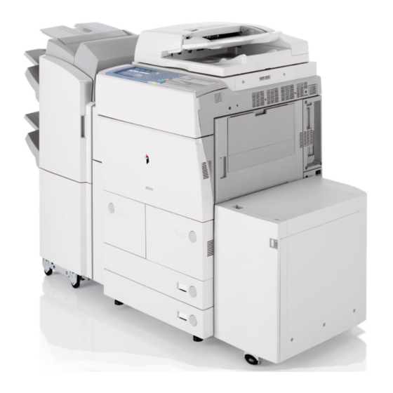
Illustrations Used in This Manual Illustrations used in this manual are those displayed when the imageRUNNER 6570 has the following optional equipment attached to it: the Saddle Finisher-T2 and Puncher Unit-M1. -
Page 18: Operations And Terms Used In This Manual
Operations and Terms Used in This Manual This machine makes effective use of memory to perform print operations efficiently. For example, as soon as the machine has scanned the original that you want to copy, it can immediately scan the next person's original. You can also print from this machine, using a function other than the Copy function. - Page 19 Copying Printing data scanned from an original, followed by finishing options, such as stapling. xvii...
-
Page 20: Legal Notices
Legal Notices FCC (Federal Communications Commission) Note: This equipment has been tested and found to comply with the limits for a Class A digital device, pursuant to Part 15 of the FCC Rules, and the limits for an ISM equipment, pursuant to Part 18 of the FCC Rules. There limits are designed to provide reasonable protection against harmful interference when the equipment is operated in a commercial environment. -
Page 21: Laser Safety
Laser Safety This product complies with 21 CFR Chapter 1 Subchapter J as a Class I laser product under the U.S. Department of Health and Human Services (DHHS) Radiation Performance Standard according to the Radiation Control for Health and Safety Act of 1968. Also, this product is certified as a Class I laser product under IEC60825-1:1993 and EN60825-1:1994. -
Page 22: Abbreviations Used In This Manual
In this manual, product names and model names are abbreviated as follows: NetWare Novell NetWare ® International Energy Star Program ® As an Partner, Canon USA, Inc. has determined NERGY ® that this machine meets the Program guidelines NERGY for energy efficiency. -
Page 23: Trademarks
Trademarks Canon, the Canon logo, imageRUNNER, MEAP and NetSpot are registered trademarks, and the MEAP logo and NetSpot Accountant are trademarks, of Canon Inc. in the United States and may also be trademarks or registered trademarks in other countries. Adobe, Adobe Acrobat, PostScript, and PostScript 3 are trademarks of Adobe Systems Incorporated. -
Page 24: Copyright
Disclaimers The information in this document is subject to change without notice. CANON INC. MAKES NO WARRANTY OF ANY KIND WITH REGARD TO THIS MATERIAL, EITHER EXPRESS OR IMPLIED, EXCEPT AS PROVIDED HEREIN, INCLUDING WITHOUT LIMITATION, THEREOF, WARRANTIES AS TO MARKETABILITY, MERCHANTABILITY, FITNESS FOR A PARTICULAR PURPOSE OF USE OR NON-INFRINGEMENT. -
Page 25: Legal Limitations On The Usage Of Your Product And The Use Of Images
Legal Limitations on the Usage of Your Product and the Use of Images Using your product to scan, print or otherwise reproduce certain documents, and the use of such images as scanned, printed or otherwise reproduced by your product, may be prohibited by law and may result in criminal and/or civil liability. A non-exhaustive list of these documents is set forth below. -
Page 26: Important Safety Instructions
If these items are dropped or spilled inside the machine, immediately turn OFF the main power switch, and disconnect the power cord from the power outlet. Then, contact your local authorized Canon dealer. - Necklaces and other metal objects - Cups, vases, flowerpots, and other containers filled with water or liquids... - Page 27 CAUTION • Do not install the machine in unstable locations, such as unsteady platforms or inclined floors, or in locations subject to excessive vibrations, as this may cause the machine to fall or tip over, resulting in personal injury. • Never block the ventilation slots and louvers on the machine.
-
Page 28: Power Supply
Power Supply WARNING • Do not damage or modify the power cord. Also, do not place heavy objects on the power cord, or pull on or excessively bend it, as this could cause electrical damage and result in a fire or electrical shock. •... -
Page 29: Handling
If the machine makes strange noises, or gives off smoke, heat, or strange smells, immediately turn OFF the main power switch, and disconnect the power cord from the power outlet. Then, contact your local authorized Canon dealer. Continued use of the machine in this condition may result in a fire or electrical shock. - Page 30 CAUTION • Do not place heavy objects on the machine, as they may tip over or fall resulting in personal injury. • Close the feeder gently to avoid catching your hands, as this may result in personal injury. • Do not press down hard on the feeder when using the platen glass to make copies of thick books.
- Page 31 • The laser beam can be harmful to human bodies. Since radiation emitted inside the product is completely confined within protective housings and external covers, the laser beam cannot escape from the machine during any phase of user operation. Read the following remarks and instructions for safety. •...
-
Page 32: Maintenance And Inspections
Maintenance and Inspections WARNING • When cleaning the machine, first turn OFF the main power switch, then disconnect the power cord. Failure to observe these steps may result in a fire or electrical shock. • Disconnect the power cord from the power outlet regularly, and clean the area around the base of the power plug's metal pins and the power outlet with a dry cloth to ensure that all dust and grime is removed. -
Page 33: Consumables
CAUTION • The fixing unit and its surroundings inside the machine may become hot during use. When removing jammed paper or when inspecting the inside of the machine, do not touch the fixing unit and its surroundings, as doing so may result in burns or electrical shock. -
Page 34: Other Warnings
Other Warnings WARNING For cardiac pacemaker users: This product generates a low level magnetic field. If you use a cardiac pacemaker and feel abnormalities, please move away from the product and consult your doctor. xxxii... -
Page 35: Periodic Inspection Of The Breaker
Make sure that the main power is turned OFF, before inspecting the breaker. • If a malfunction occurs after an inspection, contact your local authorized Canon dealer. Checking the Breaker Push the test button with the tip of a ball-point pen, or a similar object. - Page 36 If the breaker lever does not switch to the OFF (" " side) position, repeat step 1. • If the breaker lever does not switch to the OFF (" " side) position, despite carrying out the above procedure two or three times, contact your local authorized Canon dealer. Switch the breaker lever to ON ("I" side).
- Page 37 Press the main power switch to ON ("I" side). side) I side) Fill in the check sheet, located on the next page, to document your periodic inspections of the breaker. xxxv...
-
Page 38: Check Sheet For The Periodic Inspection Of The Breaker
Fill in the date of inspection and the name of the inspector. When the inspection is completed successfully, write a check mark under "OK." If not, contact your local authorized Canon dealer. (Also, write a check mark under "NG" (No Good).) -
Page 39: Before You Start Using This Machine
Before You Start Using This Machine CHAPTER This chapter describes what you should know before using this machine, such as parts and their functions, and how to turn ON the main power. Installation Location and Handling ......... . 1-2 Installation Precautions . -
Page 40: Installation Location And Handling
Installation Location and Handling This section describes precautions for installation location and handling. We recommend that you read this section prior to using this machine. Installation Precautions Avoid Installing the Machine in the Following Locations ■ Avoid locations subject to temperature and humidity extremes, whether low or high. - Page 41 ■ Avoid installing the machine in direct sunlight. If this is unavoidable, use curtains to shade the machine. Be sure that the curtains do not block the machine's ventilation slots or louvers, or interfere with the power cord and outlet. ■...
- Page 42 ■ Avoid locations where a considerable amount of dust accumulates. ■ Avoid locations where ammonia gas is emitted. ■ Avoid locations near volatile or flammable materials, such as alcohol or paint thinner. ■ Avoid locations that are subject to vibration. For example, avoid installing the machine on unstable floors or stands.
- Page 43 ■ Avoid exposing the machine to rapid changes in temperature. If the room in which the machine is installed is cold but rapidly heated, water droplets (condensation) may form inside the machine. This may result in a noticeable degradation in the quality of the copied image, the inability to properly scan an original, or the copies having no printed image at all.
-
Page 44: Select A Safe Power Supply
Select a Safe Power Supply ■ Plug the machine into a 120 V AC outlet. ■ Make sure that the power supply for the machine is safe, and has a steady voltage. ■ Do not connect other electrical equipment to the same power outlet to which the machine is connected. -
Page 45: Provide Adequate Installation Space
Provide Adequate Installation Space ■ Provide enough space on each side of the machine for unrestricted operation. The optional Copy Tray-L1 is attached. 4" (100 mm) or more 50 3/8" (1,278 mm) 57 1/2" (1,448 mm) The optional Saddle Finisher-T2, Puncher Unit-M1, and Paper Deck-V1 are attached. -
Page 46: Moving The Machine
Moving the Machine ■ If you intend to move the machine, even to a location on the same floor of your building, contact your local authorized Canon dealer beforehand. Handling Precautions ■ Do not attempt to disassemble or modify the machine. - Page 47 ■ If there is smoke, or unusual noise, immediately turn the main power switch OFF, disconnect the power cord from the outlet, and call your local authorized Canon dealer. Using the machine in this state may cause a fire or electrical shock. Also, avoid placing objects around the power plug so that the machine can be disconnected whenever necessary.
- Page 48 ■ Do not turn the main power switch OFF or open the front covers while the machine is in operation. This might result in paper jams. ■ Do not use flammable sprays, such as spray glue, near the machine. There is a danger of ignition.
- Page 49 Neither Canon nor any service provider will be liable for damages for loss of data stored on the product's hard disk drive.
-
Page 50: Parts And Their Functions
Parts and Their Functions This section provides you with the names and functions of all the parts on the outside and inside of the main unit, control panel, and the touch panel display. An illustration of the machine with some optional equipment attached to it is also provided. - Page 51 c Stack Bypass g Paper Drawers 3 and 4 Use the stack bypass to feed paper manually Holds up to 550 sheets of paper (20 lb bond and for loading nonstandard paper stock. (See (80 g/m "Making Prints Using the Stack Bypass," on p. h Paper Drawers 1 and 2 2-41.) Holds up to 1,500 sheets of paper (20 lb bond...
- Page 52 The optional Finisher-T1, Puncher Unit-M1, and Paper Deck-V1 are attached. 1-14 Parts and Their Functions...
-
Page 53: Internal View
Internal View The optional Saddle Finisher-T2 and Puncher Unit-M1 are attached. a Platen Glass d Fixing Unit (Unit1) Place originals here when scanning books, thick Pull out the fixing unit to clear a paper jam. (See originals, thin originals, transparencies, etc. "Main Unit (Fixing Unit and Duplexing Unit),"... -
Page 54: Feeder Parts And Functions
Feeder Parts and Functions Originals placed in the feeder are automatically fed sheet by sheet to the platen glass for scanning. The feeder also automatically turns over two-sided originals to make one or two-sided copies. CAUTION Do not insert your fingers into the gaps around the original supply tray, as your fingers may get caught. -
Page 55: Control Panel Parts And Functions
If you lose Press to clear entered values or characters. the edit pen, contact your local authorized Canon dealer. Do not use an object with a sharp l Numeric keys end, such as a pencil or ballpoint pen, instead of Press to enter numerical values. -
Page 56: Main Power And Control Panel Power
Main Power and Control Panel Power The machine is provided with two power switches, a main power switch and a control panel power switch, as well as a breaker that detects excess current or leakage current. How to Turn ON the Main Power This section explains how to turn ON the main power. - Page 57 IMPORTANT If the main power indicator on the control panel does not light even though the main power switch is ON, be sure to check the breaker to see if it is OFF. (See "When the Power Does Not Turn ON," on p. 9-88.) The screens shown below are displayed while the system software is loading.
- Page 58 IMPORTANT • If you turn OFF the main power, wait at least 10 seconds before turning the main power back ON. • Do not turn the main power OFF if the optional Universal Send Kit is activated, or if the optional Super G3 FAX Board is installed, and you want to be able to send or receive I-fax or fax documents.
- Page 59 ● If login authentication by a login service (SDL or SSO) is not set, and MEAP is selected as the initial function in Common Settings (from the Additional Functions screen): ❑ The Start Up screen is displayed until the machine is ready to scan. ❑...
- Page 60 The MEAP Application screen is displayed. Press [➞] to switch to the Basic Features screen. IMPORTANT • If you turn OFF the main power, wait at least 10 seconds before turning the main power back ON. • Do not turn the main power OFF if the optional Universal Send Kit is activated, or if the optional Super G3 FAX Board is installed, and you want to be able to send or receive I-fax or fax documents.
- Page 61 ❑ After the Start Up screen disappears, the MEAP Start Up screen is displayed regardless of the Initial Function settings. (The background color of the screen is changed to brown.) The Login screen is displayed. The SDL Login Screen The SSO Login Screen 1-23 Main Power and Control Panel Power...
- Page 62 IMPORTANT • If you turn OFF the main power, wait at least 10 seconds before turning the main power back ON. • Do not turn the main power OFF if the optional Universal Send Kit is activated, or if the optional Super G3 FAX Board is installed, and you want to be able to send or receive I-fax or fax documents.
- Page 63 ● If the message <Enter the Dept. ID and Password using the numeric keys.> appears: ❑ Press [Dept. ID] ➞ enter the Department ID using (numeric keys). ❑ Press [Password] ➞ enter the password using (numeric keys). ❑ Press (ID). The Basic Features screen is displayed.
- Page 64 ● If the message <Enter a user name and password and press the [Log In] key.> appears: ❑ Press [User Name] ➞ enter the user name ➞ press [OK]. ❑ Press [Password] ➞ enter the password ➞ press [OK]. ❑ Press [Log In].
-
Page 65: Control Panel Power Switch
Control Panel Power Switch Press the control panel power switch to cancel the Sleep mode and resume normal machine operations. NOTE • The machine can receive and print documents from a personal computer when it is in the Sleep mode. I-fax and fax documents can also be received while the machine is in the Sleep mode. -
Page 66: Shutting Down The Machine
Shutting Down the Machine If there are any jobs currently being processed, or a MEAP application is running when the Shutdown mode is activated, the machine asks you to confirm and cancel any existing jobs, and then access to the hard disk is restricted. This procedure protects the hard disk from access errors the next time the machine is turned ON. - Page 67 Confirm the jobs currently being processed or waiting to be processed ➞ press [Start]. Jobs continue to be processed until [Start] is pressed. To cancel the Shutdown mode, press [Cancel]. If there are no current jobs, proceed to step 4. NOTE •...
- Page 68 Confirm the message displayed ➞ press [Yes]. If There Are Jobs Currently Being Processed or Waiting to Be Processed If a Font Is Being Downloaded To return to the job confirmation screen, press [No]. All of the jobs on the confirmation screen being processed or waiting to be processed are canceled.
- Page 69 [Yes]. However, as it is possible that this will destroy data which is being processed or cause damage to the machine, it is not recommended. Note that Canon will not be liable for any damages resulting from the loss of data on the hard disk drive. For more information, contact your local authorized Canon dealer.
- Page 70 NOTE • It may take some time for the machine to completely shut down because of the internal cooling down process and the status of the network. • The screen below is displayed when you press [Forced Off] in any of the following cases.
- Page 71 After the machine shuts down, press the main power switch to OFF (" " side). side) ( side) IMPORTANT The machine may continue to operate during or after the shutdown process. Do not unplug the power cord until the device sounds stop. 1-33 Main Power and Control Panel Power...
-
Page 72: System Settings
System Settings It is necessary to set up the machine before using it on a network, as a printer, or with the Fax function. To set up the machine, refer to the following guides or sections for instructions: ■ Connecting the Machine to the Network See the Network Quick Start Guide. -
Page 73: Basic Operations
What This Machine Can Do ..........2-2 Overview of the imageRUNNER 6570/5570/5070 ......2-6 The Touch Panel Display . -
Page 74: What This Machine Can Do
Send Mail Box Equipped with features that meet the needs of document work in a digitized office, the imageRUNNER 6570/5570/ 5070 represents the ultimate in digital multitasking machines. Remote UI Copying See the Copying Guide In addition to normal copying functions, convenient new functions, such as "Sample... - Page 75 Sending Function (optional)* See the Sending and Facsimile Guide The Send function enables you to send Original scanned image or document data to file servers, or send it by e-mail or I-fax. A variety of file formats are supported (PDF, TIFF, and PDF (OCR)), which offer you greater flexibility in accommodating digital E-mail...
- Page 76 Ethernet connection interface. Once the Ethernet interface port is configured properly, the imageRUNNER 6570/5570/ 5070 can be controlled and set up through the Remote UI and network. Also, you can use the Remote UI to fax from your PC using the Ethernet connection.
-
Page 77: Network Scanning
Network Scanning* See the Network ScanGear User's Guide The Network Scan function enables you to use the imageRUNNER 6570/5570/5070 as Original a conventional scanner. You can scan a document using the machine, and read the data in an application you are using on your... -
Page 78: Overview Of The Imagerunner 6570/5570/5070
Overview of the imageRUNNER 6570/5570/5070 Most operations on this machine are executed from the touch panel display. By pressing the keys according to the instructions on the touch panel display, you can utilize almost all of the functions of this machine. -
Page 79: Switching The Functions Indicated On The Touch Panel Display
You can set the initial screen (the first screen that appears when the machine is turned ON) from the Additional Functions screen. The initial screen can be the Copy, Send or Fax, Mail Box, MEAP , or System Monitor screen. Overview of the imageRUNNER 6570/5570/5070... - Page 80 Printer Mail Box Function," in the Mail Box Guide.) Press this key to access the machine's printing d Scan functions. Press this key to use the Network Scan function. (See the Network ScanGear User's Guide.) Overview of the imageRUNNER 6570/5570/5070...
-
Page 81: Various Touch Panel Display Screens
Universal Send Kit (activated) Super G3 FAX Board imagePASS and Super G3 FAX Board Universal Send Kit (activated), and Super G3 FAX Board imagePASS, Universal Send Kit (activated), and Super G3 FAX Board Overview of the imageRUNNER 6570/5570/5070... -
Page 82: Adding New Functions
For each application, you can set the terms of validity and impression limits for scan, print, or copy jobs. NOTE For details on obtaining licenses, contact your local authorized Canon dealer. ■ User Management and Restriction Using a Login Service A login service manages data relating to users using the machine. The following three login services are available: •... -
Page 83: Specifying Settings
Address Book Settings: The Sending and Facsimile Guide • Mail Box Settings: The Mail Box Guide • Printer Settings: The PS/PCL/UFR II Printer Guide • Network Settings: The Network Guide The Additional Functions Screen 2-11 Overview of the imageRUNNER 6570/5570/5070... - Page 84 [Communications Settings], [Forwarding Settings], [Restrict Access to Destinations], and [Register LDAP Server] are displayed on the System Settings screen only if the optional Universal Send Kit is activated, or the optional Super G3 FAX Board is installed. 2-12 Overview of the imageRUNNER 6570/5570/5070...
-
Page 85: Functions That Conserve Power
(Energy Saver) again. NOTE The Energy Saver mode's energy conservation level can be set to '-10%', '-25%', '-50%', or 'None'. The default setting is '-10%'. (See "Energy Saver Mode," on p. 4-44.) 2-13 Overview of the imageRUNNER 6570/5570/5070... -
Page 86: Checking, Changing, And Canceling Print Jobs
"Daily Timer Settings," on p. 5-8.) Checking, Changing, and Canceling Print Jobs The System Monitor screen enables you to check the status of the machine, cancel print jobs, or specify the printing priority. The System Monitor Screen (Print) 2-14 Overview of the imageRUNNER 6570/5570/5070... - Page 87 Icon (Type of Job) Description Copy Job Send/Fax Job Mail Box Job Printer Job Report Job Network Scan Job Additional Functions Job Icon (Machine Status) Description Error Paper Jam Staple Jam Replace Toner Cartridge 2-15 Overview of the imageRUNNER 6570/5570/5070...
-
Page 88: Displaying A Help Screen
[Special Features] ➞ [Margin], the Help Function screen appears as shown below. The Help Function Screen To display the Help Menu screen, press [Help Menu]. To return to the screen for setting the Margin mode, press [Done]. 2-16 Overview of the imageRUNNER 6570/5570/5070... - Page 89 Press [Photo original] or [Originals with Text/Photo] ➞ press [▼] or [▲] to read the detailed information on the selected mode. Press [Done] to return to the Various Originals screen. Press [Done] to return to the Help Menu screen. 2-17 Overview of the imageRUNNER 6570/5570/5070...
-
Page 90: Reading Messages From The System Manager
For instructions on erasing the message board, see "Clearing the Message Board," on p. 7-43. Types of Message Boards The following three types of message boards are available: ■ A Message Board without [Done] 2-18 Overview of the imageRUNNER 6570/5570/5070... - Page 91 The message appears again when the main power is turned OFF, and then turned back ON, or after the Auto Clear mode has activated. ■ A Message Board Where the Message Appears in the Job/Print Status Display Area Job/Print Status Display Area 2-19 Overview of the imageRUNNER 6570/5570/5070...
-
Page 92: Other Useful Functions
NOTE Even if Job Duration Display is set to 'On', the job duration time is not displayed when the wait time is less than one minute. (See "Job Duration Display," on p. 4-87.) 2-20 Overview of the imageRUNNER 6570/5570/5070... -
Page 93: Paper Supply Indicator
There are four different paper supply indicators, as shown below: Display Remaining Paper Paper drawer is approximately 50% - 100% full. Paper drawer is approximately 10% - 50% full. Paper drawer is less than 10% full. Paper drawer is empty. 2-21 Overview of the imageRUNNER 6570/5570/5070... -
Page 94: Auto Orientation
Even if Auto Orientation is set to 'On', the image is not rotated if the Different Size Originals, Cover/Sheet Insertion, Staple (Double), Transparency Interleaving, XY Zoom, Shift, Image Repeat, or Tab Paper Creation mode is set. (See Chapter 10, "Customizing Settings," in the Copying Guide.) 2-22 Overview of the imageRUNNER 6570/5570/5070... -
Page 95: Using The Touch Panel Display
Using the Touch Panel Display This section describes the keys that are frequently used on the touch panel display. Information on how to adjust the brightness of the touch panel display is also provided. CAUTION Press the touch panel display keys gently with your fingers or the edit pen. Do not press the touch panel display with a pencil, ballpoint pen, or other sharp objects that can scratch the surface of the touch panel display or break it. -
Page 96: Touch Panel Key Display
Touch Panel Key Display When you press a key on the touch panel display, that key is highlighted, and the corresponding mode is set. When you set certain modes, the characters on some keys may become grayed out. You cannot press keys that are grayed out. This means that you cannot set these modes in combination with the presently set mode. -
Page 97: Numeric Keys
Keys that have a colored triangle ( ) in the lower right corner and that appear on screens for storing settings, are keys that already have settings stored in them. Settings Are Stored No Settings Are Stored ■ Keys That Display a Drop-Down List Pressing a key that has a down triangle (▼) to the right of the name of the selection, displays a drop-down list containing other setting options. -
Page 98: Adjusting The Brightness
Adjusting the Brightness If the touch panel display is difficult to view, use the display contrast dial on the control panel to adjust its brightness. Display Contrast Lighter Darker NOTE To make the touch panel display brighter, turn the dial counterclockwise. To make it darker, turn the dial clockwise. -
Page 99: Entering Characters From The Touch Panel Display
When entering characters on the SDL or SSO authentication screen or in MEAP application functions, the character entry screens may appear differently. Alphanumeric Characters Example: Enter <Canon>. To enter alphanumeric characters, make sure that <Alphanum.> is displayed on the entry mode drop-down list. - Page 100 Enter <Canon>. To enter uppercase letters, press [Shift]. To enter a space, press [Space]. To move the cursor, press [ ] or [ ]. To enter symbols, press the entry mode drop-down list ➞ select [Symbol] ➞ enter the desired symbols.
-
Page 101: Symbols
Symbols Example: Enter <é>. Press the entry mode drop-down list ➞ select [Symbol]. Press [▼] or [▲] to display the desired symbol that you want to enter. 2-29 Entering Characters from the Touch Panel Display... - Page 102 Press [é]. To enter a space, press [Space]. To move the cursor, press [ ] or [ ]. To enter alphanumeric characters, press the entry mode drop-down list ➞ select [Alphanum.] ➞ enter the desired characters. The characters you entered are displayed, as shown below. NOTE •...
-
Page 103: Values In Inches
Values in Inches If you want to enter values in inches in all modes which require a numeric entry, set Inch Entry to 'On' in Common Settings (from the Additional Functions screen). (See "Inch Entry," on p. 4-35.) This enables you to enter values in inches when you press [Inch] on a screen requiring a numeric entry or measurement. -
Page 104: Entering The Department Id And Password
Entering the Department ID and Password If Department ID Management has been set, the Department ID and password must be entered before using this machine. NOTE • For instructions on setting the Department ID and password, see "Department ID Management," on p. 7-9. •... - Page 105 NOTE If you make a mistake when entering the Department ID or password, press (Clear) ➞ enter the correct values. Press (ID). Additional Functions PQRS WXYZ Star Display Contrast Clear Processing/Data The Basic Features screen of the selected function appears on the touch panel display.
-
Page 106: Control Panel
When your operations are complete, press (ID) on the control panel. If you are using a control card, remove the control card, and take it with you. (See "Card Reader-C1," on p. 3-20.) Additional Functions PQRS WXYZ Star Display Contrast Clear Processing/Data The screen for entering the Department ID and password appears. -
Page 107: Using A Login Service
Using a Login Service If you are managing the machine with a login service, such as SDL (Simple Device Login) or SSO (Single Sign-On), enter the user name and password before using this machine. NOTE • SDL and SSO are used as examples to explain the procedure. However, if you are using a different login service, the login procedure may vary. - Page 108 If SSO is set as a login service, the login destination is also displayed. IMPORTANT • To use the Domain Authentication system of SSO (including when performing domain authentication with the 'Domain Authentication + Local Device Authentication' system), a Windows server in which Active Directory is installed, and Security Agent are necessary.
- Page 109 Enter the user name ➞ press [OK]. NOTE For instructions on entering characters, see "Entering Characters from the Touch Panel Display," on p. 2-27. Press [Password]. The SDL Login Screen 2-37 Using a Login Service...
- Page 110 Enter the password ➞ press [OK]. If SSO is set as the login service, select the login destination. NOTE • If the Domain Authentication system of SSO (including when performing domain authentication with the 'Domain Authentication + Local Device Authentication' system) is being used, users who belong to up to four trusted domains (including the domain to which the machine belongs), can select his/her desired login destination.
- Page 111 Press [Log In]. The SDL Login Screen You can also press (ID) instead of [Log In] to log on. If the user name or password that you entered is incorrect, a message appears prompting you to verify your user name and password. Repeat the procedure from step 1.
- Page 112 NOTE • To perform operations again, you have to re-enter your user name and password. • If you do not press (ID) after you are finished operating the machine, any subsequent copies made are added to the total of the user who previously logged on to the machine.
-
Page 113: Making Prints Using The Stack Bypass
Making Prints Using the Stack Bypass If you are making prints on tracing paper, labels, transparencies, or nonstandard paper size stock, load the paper stock into the stack bypass. IMPORTANT • Note the following points when using the stack bypass: - Paper Quantity: one to approximately 50 sheets (20 lb bond (80 g/m ), stack approximately 1/4"... - Page 114 - Originals with an extremely dark background - STMT or STMTR originals that are placed on the platen glass • For high-quality printouts, use paper recommended by Canon. • For more information on paper types that can be used with this machine, see "Available Paper Stock,"...
- Page 115 ● If the paper loaded in the stack bypass is not the paper that you want to specify: ❑ Check to see if any job is reserved. (See "Checking Job Status," on p. 6-6.) If there is a current or reserved job, you can reserve a change of paper for the Copying stack bypass.
- Page 116 Load the paper into the stack bypass. Make sure that the height of the paper stack does not exceed the loading limit mark ( When you use the stack bypass to make copies, straighten out curled paper prior to use, as shown below. Curled paper may cause a paper jam. Feeding Direction To print on the back side of preprinted paper, load it face down into the stack bypass, as shown in the illustration below.
- Page 117 IMPORTANT When loading paper into the stack bypass, align the paper stack neatly between the slide guides. If the paper is not loaded correctly, a paper jam may occur. NOTE • If there are instructions on the paper package about which side of the paper to load, follow those instructions.
- Page 118 ● If you want to select a nonstandard paper size: ❑ Press [Free Size] ➞ [Next]. IMPORTANT Set the paper size to the same size as the paper loaded in the stack bypass. NOTE If the following screen is displayed, press [OK] ➞ adjust the width of the slide •...
- Page 119 • If the following screen is displayed, adjust the width of the slide guides to match the paper size stored in Stack Bypass Standard Settings, or set Stack Bypass Standard Settings to 'Off' in Common Settings (from the Additional Functions screen).
- Page 120 Press [Done]. Paper Size/Type Selected Paper Size/Type Currently Loaded If you press [Stack Bypass Settings], follow the procedures and screens in steps 4 and 5 to reset the paper size and type settings. If the Copy function is selected, place your originals ➞ select the desired copy settings.
-
Page 121: Multifunctional Operations
Multifunctional Operations The imageRUNNER 6570/5570/5070 offers the user many functions, such as printing, scanning, copying, and sending, which can be used together. The following table provides you with the details of multifunctional operations. ■ How to read the table The table on the following page indicates the availability of the operations listed in the horizontal rows when the operations listed in the vertical columns are already being performed. - Page 122 Receive Send Scan Print Copy: Scan Copy/ Net- Print Net- Send Print Mail Copy Docu- work Data work Data Print ment Net- work Receive via Fax Print Data Net- Send work via Fax *4*6 *4*6 *4*6 Copy/ Mail Scan Send *4*6 *4*6 *4*6...
- Page 123 NOTE • The machine's performance may not be optimal even if the combinations of operations are available. • The machine's performance may be affected if several network send and receive jobs are being carried out at the same time. • The operation of printing data from an inbox is included in "Print Data"...
-
Page 124: Available Paper Stock
Available Paper Stock The paper types that can be used with this machine are shown in the following table. Icons indicating the type of paper loaded in each paper drawer can be displayed on the paper selection screen if you store that information in the machine beforehand. - Page 125 Paper Source Paper Size Width x Length Paper Paper Paper Stack Drawer Drawer Deck Bypass 1 and 2 3 and 4 (optional) 11" x 17" 11" x 17" 8 1/2" x 14" 8 1/2" x 11" LTRR 11" x 8 1/2" STMTR 5 1/2"...
- Page 126 2-54 Available Paper Stock...
- Page 127 Optional Equipment CHAPTER This chapter describes the uses of optional equipment, and their special functions. System Configuration ........... . 3-2 Optional Equipment .
-
Page 128: Optional Equipment
System Configuration This section provides you with illustrations of all the optional equipment that can be attached to the machine, and shows you examples of different system configurations. Optional Equipment System Configuration... - Page 129 a Copy Tray-L1 d Puncher Unit-M1 The Copy Tray-L1 is equipped with the following The Puncher Unit-M1 is equipped with the Hole features: Collate, Group, and Rotate. Punch mode. The Puncher Unit-M1 can be attached only if the Finisher-T1 or Saddle b Card Reader-C1 Finisher-T2 is attached.
-
Page 130: Sample System Configurations
The illustrations below are only examples of some of the possible system configurations. For information on the complete range of optional equipment configurations, contact your local authorized Canon dealer. The optional Copy Tray-L1 is attached. The optional Finisher-T1, Puncher Unit-M1, and Paper Deck-V1 are attached. -
Page 131: System Options
Installing the Super G3 FAX Board enables you to fax documents that have been created in applications directly from your PC via a network. NOTE The Canon Fax Driver is supplied with the Super G3 FAX Board, and enables you to send fax images from a PC via the machine. ■ Universal Send Kit The Universal Send Kit enables you to send scanned documents via e-mail or I-fax, as well as send scanned data to be stored in file servers or User Inboxes. - Page 132 ■ Universal Send PDF Enhancement Kit The Universal Send PDF Enhancement Kit improves the performance of PDF files created on the machine. It enables you to encrypt the PDF files and set a password to send them safely to a file server or e-mail address. It also enables you to create PDF (OCR) files from scanned documents using OCR (Optical Character Recognition).
-
Page 133: Available Combination Of Options
Available Combination of Options This table describes the optional equipment that is needed to use each function, the available combination of options that can be installed simultaneously, and the limitations when installing optional equipment. Optional Simultaneous Installation Machine Equipment Function Required Limitations Needed... - Page 134 Simultaneous Installation Machine Optional Function Equipment Needed Required Limitations Large Scale Paper Paper Deck-V1 Supply To use the Security Management function, Expansion Bus the iR Security Kit Security Management iR Security Kit and USB must be activated after (Hard Disk and Job (activated) Application the Expansion Bus...
-
Page 135: Paper Deck-V1
Paper Deck-V1 If you attach the Paper Deck-V1 to the machine, you have one additional source of paper for print jobs. Up to 3,500 sheets of paper (20 lb bond (80 g/m )) can be loaded into the paper deck. IMPORTANT If the machine is in the Sleep mode (the touch panel is not displayed, and only the main power indicator is lit), you may not be able to open the paper deck. -
Page 136: Finisher-T1/Saddle Finisher-T2/Puncher Unit-M1
Finisher-T1/Saddle Finisher-T2/Puncher Unit-M1 The Finisher-T1 and Saddle Finisher-T2 are equipped with the following finishing modes: Collate, Group, Offset, and Staple. The Saddle Finisher-T2 is also equipped with the Saddle Stitch mode. The Puncher Unit-M1 is equipped with the Hole Punch mode. IMPORTANT If the optional Copy Tray-L1 is attached, you cannot attach an optional finisher. - Page 137 a Top Cover of the Finisher f Booklet Tray (Saddle Finisher-T2 Only) Open this cover to remove jammed paper. (See Prints that are saddle stitched are output to this "Inside the Top Cover of the Finisher-T1/Saddle tray. Finisher-T2 (Optional)," on p. 9-39.) g Booklet Tray Guide (Saddle Finisher-T2 b Top Cover of the Puncher Unit-M1 Only)
-
Page 138: Finishing Modes
Finishing Modes The Finisher-T1 and Saddle Finisher-T2 are equipped with the following finishing modes. CAUTION • Do not place anything other than output paper in the trays of the finisher, as doing so may damage the trays. • Do not place anything under the trays of the finisher, as doing so may damage the trays. - Page 139 NOTE If you press [Offset] when either the Collate or Group mode is set, each set of prints is shifted approximately 1 1/4" (30 mm) before it is delivered to the output tray. ■ Staple Mode The prints are automatically collated into sets arranged in page order and stapled. Prints are stapled in the following places: •...
- Page 140 CAUTION Do not place your hand in the part of the tray where stapling is performed if a finisher is attached, as this may result in personal injury. IMPORTANT • If the Staple mode is set, the output trays move downward as the stack of paper that is output increases in quantity and thickness.
- Page 141 NOTE • The maximum number of sheets, including cover sheets, that can be stapled together is as follows (only 17 to 24 lb bond (64 to 90 g/m ) paper can be used for the main document, and 17 lb bond to 110 lb index (64 to 200 g/m ) paper can be used for the cover page): - LTR, EXEC...
- Page 142 IMPORTANT • The Saddle Stitch mode is available only if the Saddle Finisher-T2 is attached. • The maximum number of sheets, including cover sheets, that can be saddle stitched is: - 15 sheets (17 to 20 lb bond (64 to 80 g/m - 10 sheets (20 to 24 lb bond (81 to 90 g/m •...
-
Page 143: Hole Punch Mode
■ Hole Punch Mode The Hole Punch mode punches two or three holes (depending on the paper size) in the printed sheets. NOTE • The hole punched areas are shown in the illustration below. Platen Glass Feeder Hole Hole Punched Punched Area Area... - Page 144 IMPORTANT • The Hole Punch mode is available only if the Puncher Unit-M1 is attached. • Only the following paper sizes can be hole punched: 11" x 17", LGL, LTR, LTRR, or EXEC. • Holes cannot be punched in transparencies, tracing paper, labels, or pre-punched paper. •...
-
Page 145: Copy Tray-L1
Copy Tray-L1 If the Copy Tray-L1 is attached to the machine, the following modes are available: IMPORTANT The Copy Tray-L1 can be attached to the machine only if no optional finisher is attached. ■ Collate Mode The prints are automatically collated into sets arranged in page order before they are delivered to the output tray. -
Page 146: Card Reader-C1
Card Reader-C1 If the Card Reader-C1 is attached to the machine, you must insert a control card to operate it. The Card Reader-C1 performs Department ID Management automatically. IMPORTANT • If you are using a login service other than default authentication, the Limit Functions mode will not be available. -
Page 147: Procedure Before Using The Machine
Procedure before Using the Machine Insert the control card into the card slot, making sure that it is facing in the correct direction. The Basic Features screen of the selected function appears on the touch panel display. 3-21 Card Reader-C1... -
Page 148: Procedure After Using The Machine
Procedure after Using the Machine After you finish using the machine, remove the control card. The touch panel display returns to the screen for inserting the control card. If SDL is set as the login service, the following screen is displayed. 3-22 Card Reader-C1... -
Page 149: Department Id Management
IMPORTANT Once you have removed the control card, you cannot operate the machine until the control card is inserted again. Department ID Management This section describes how to change the password and page limit, and how to check the print totals when a control card is being used. NOTE •... - Page 150 Press [Dept. ID Management]. NOTE If the desired setting is not displayed, press [▼] or [▲] to scroll to the desired setting. Press [Register Dept. ID/Password]. 3-24 Card Reader-C1...
- Page 151 Press [▼] or [▲] to display the department whose password you want to change ➞ select the department ➞ press [Edit]. NOTE Press and hold down [▼] or [▲] to quickly and continuously scroll through the available Department ID pages. Continuous scrolling is useful when a large number of Department IDs are registered.
- Page 152 If you want to change or set a page limit restriction, press [Turn Limits On/Off and Set Page Limits]. Press [On] under the desired function(s). If you do not want to set a page limit restriction for a function, press [Off] under the desired function's name.
- Page 153 Press [ ] (Page Limit) next to [On]/[Off] of the desired function(s) ➞ enter the page limit restriction using (numeric keys). IMPORTANT • The machine stops sending a fax if the Scan Limit is reached while faxing a document either from memory or directly to the recipient. •...
- Page 154 Press [OK] ➞ [OK]. The page limits for the selected functions are set. If you would like to limit users to certain functions of the machine, press [Limit Functions]. 3-28 Card Reader-C1...
- Page 155 Select [On] or [Off] next to the functions (other than the Copy function) you want to limit using Department ID Management ➞ press [OK]. Details of each item are shown below. [On]: Department ID Management is set for the selected function(s). [Off]: Department ID Management is set only for copying or printing operations from computers.
- Page 156 Press [OK]. Department ID Management is set. Press [Done] repeatedly until the Basic Features screen appears. If the page limit setting is set to 'On', the remaining number of pages that can be printed (page limit minus the current page count) is displayed on the screen, as shown below.
- Page 157 Scan Screen The icon that is displayed on the Scan screen is explained below: Remaining number of sheets that can be scanned Print Screen The icons that are displayed on the Print screen are explained below: Total number of sheets remaining that can be copied or printed Remaining number of sheets that can be printed 3-31 Card Reader-C1...
-
Page 158: Checking The Page Counts On A Control Card
Send Screen The icon that is displayed on the Send screen is explained below: Remaining number of sheets that can be scanned NOTE • Only the page limits for functions that are set to 'On' are displayed. • The Send screen appears only if the optional Universal Send Kit is activated. Checking the Page Counts on a Control Card You can check the page counts on the control card that you are currently using. - Page 159 Press [Pg Ct Check]. Check the page counts ➞ press [Done] ➞ [Done]. The display returns to the Basic Features screen. 3-33 Card Reader-C1...
-
Page 160: Checking And Printing Counter Information
Checking and Printing Counter Information You can display and print a list of how much paper was used by each department. (Additional Functions) ➞ [System Settings] ➞ Press [Dept. ID Management]. If necessary, see the screen shots in steps 1 and 2 of "Changing the Password and Page Limit,"... - Page 161 ● If you only want to check the counter information: ❑ Press [▼] or [▲] to display the desired Department ID. NOTE Press and hold down [▼] or [▲] to quickly and continuously scroll through the available Department ID pages. Continuous scrolling is useful when a large number of Department IDs are registered.
- Page 162 The screen below is displayed while the machine is printing the counter information. NOTE • To cancel printing, press [Cancel]. • To close the screen that is displayed while the machine is printing the Page Count List, press [Done]. • The counter information can be printed only if 11"...
-
Page 163: Clearing Page Totals
Press [OK]. Press [Done] repeatedly until the Basic Features screen appears. Clearing Page Totals You can clear the page totals for all departments or for specific departments. (Additional Functions) ➞ [System Settings] ➞ Press [Dept. ID Management]. If necessary, see the screen shots in steps 1 and 2 of "Changing the Password and Page Limit,"... - Page 164 Press [Clear All Totals]. To clear one page total at a time by department, press [▼] or [▲] to display the desired department ➞ select the department ➞ press [Clear]. Press [Yes]. If you do not want to clear the page totals, press [No]. 3-38 Card Reader-C1...
- Page 165 The message <Cleared.> appears for approximately two seconds on the touch panel display. The page totals are cleared. Press [Done]. 3-39 Card Reader-C1...
-
Page 166: Accepting Print And Scan Jobs With Unknown Ids
Press [OK]. Press [Done] repeatedly until the Basic Features screen appears. Accepting Print and Scan Jobs with Unknown IDs You can specify whether to accept or reject print and network scan jobs from computers that do not correspond with a registered Department ID. NOTE •... - Page 167 Select [On] or [Off] ➞ press [OK]. Allow Printer Jobs with Unknown IDs [On]: The machine accepts print jobs from computers that do not correspond with a registered Department ID. [Off]: The machine does not accept print jobs from computers that do not correspond with a registered Department ID, and you must insert a control card to operate the machine.
- Page 168 3-42 Card Reader-C1...
-
Page 169: Customizing Settings - Common Settings
Customizing Settings - Common Settings CHAPTER This chapter explains how to change the machine's Common Settings, and customize them to suit your needs. What Are Additional Functions? ..........4-3 Accessing the Additional Functions Screen . - Page 170 4. Customizing Settings - Common Settings Returning the Common Settings to Their Defaults ........4-95...
-
Page 171: What Are Additional Functions
What Are Additional Functions? Additional Functions enable you to customize the machine's various settings. IMPORTANT If SDL or SSO is set as the login service, whether you can change the System Manager Settings varies in the following way: - Users whose user type is registered as "General" cannot change the System Manager Settings, even if no System Manager ID and System Password are set. - Page 172 Press a mode key to specify its settings. For an overview of all the settings you can change from the Additional Functions screen, see "Additional Functions Settings Table," on p. 4-5. NOTE The Common Settings, Adjustment/Cleaning, System Settings, and Copy Settings screens consist of a list of individual settings.
-
Page 173: Additional Functions Settings Table
Additional Functions Settings Table The following settings can be selected or stored from the Additional Functions screen. For more information, consult the following guides. • Copy Settings: Copying Guide • Report Settings, Communications Settings, and Address Book Settings: Sending and Facsimile Guide •... - Page 174 ■ Common Settings Applicable Item Settings Delivered Page Select Initial Function: Copy , Send, Mail Box, MEAP Set [System Monitor] as the Initial Initial Function p. 4-24 Function: On, Off Set [Device] as the default screen for [System Monitor]: On , Off Auto Clear Setting Initial Function...
- Page 175 ■ Common Settings Table Continued Applicable Item Settings Delivered Page Energy Consumption , High p. 4-46 in Sleep Mode LTRR/STMT Original Distinguish Manually, Use LTRR p. 4-48 Selection Format , Use STMT Format If the Optional Finisher-T1 or Saddle Finisher-T2 Is Attached: Tray A: Copy, Mail Box, Printer, Receive/Fax , Other...
- Page 176 ■ Common Settings Table Continued Applicable Item Settings Delivered Page Paper Select: All Paper Sources, Auto Copies: 1 to 9,999 sets Finisher: If the Optional Copy Tray-L1 Is Attached: Do Not Collate, Collate , Rotate Collate, Group, Rotate Group If the Optional Finisher-T1 or Saddle Finisher-T2 Is Attached: Do Not Collate, Collate, Offset Collate...
- Page 177 ■ Common Settings Table Continued Applicable Item Settings Delivered Page Language Switch On, Off p. 4-74 Reversed Display (Color) On, Off p. 4-77 Offset Jobs , Off p. 4-79 Job Separator between Jobs p. 4-80 On, Off Job Separator between Copies p.
-
Page 178: Timer Settings
■ Timer Settings Applicable Item Settings Delivered Page Time Fine 00:00 to 23:59, in one minute p. 5-2 Adjustment increments 10 sec., 1, 2, 10, 15 , 20, 30, 40, Auto Sleep Time p. 5-4 50 min., 1 hour, 90 min., 2, 3, 4 hours 0 (Off) to 9 minutes, in one minute Auto Clear Time... - Page 179 ■ Report Settings Applicable Item Settings Delivered Page Settings: Send For Error Only , On, Off TX Report Report with TX Image: On , Off Activity Report Auto Print , Off On, Off Daily Activity Report Time Timer Setting: 00:00 to 23:59 Send/Receive On, Off Separate...
- Page 180 ■ Report Settings Table Continued Applicable Item Settings Delivered Page Print List: Send Address Book 1 to 10; Address Address Book List Book 1 One-touch Buttons, Print List User's Data List Print List Print List: Fax User's Data List Print List Print List: Network Print List: Printer *1 Indicates the default setting.
- Page 181 ■ System Settings Table Continued Applicable Item Settings Delivered Page Dept. ID Management Dept. ID Management On, Off Register Dept. ID/ Register, Edit, Erase, Limit Functions Password Page Totals Clear, Print List, Clear All Totals p. 7-9 Allow Printer Jobs with , Off Unknown IDs Allow Remote Scan...
- Page 182 ■ System Settings Table Continued Applicable Item Settings Delivered Page Fax Settings 33600 bps , 14400 bps, Send Start Speed 9600 bps, 7200 bps, 4800 bps, 2400 bps 33600 bps , 14400 bps, Receive Start Speed 9600 bps, 7200 bps, 4800 bps, 2400 bps Receive Password 20 digits maximum...
- Page 183 ■ System Settings Table Continued Applicable Item Settings Delivered Page Device Information Settings p. 7-41 Device Name 32 characters maximum Location 32 characters maximum Network Settings Receive Type, E-mail Priority, Edit, Erase, Print List Forwarding Settings Validate/Invalidate, Register (Registered Forwarding Settings), Forward w/o Conditions Clear Message Board Clear p.
- Page 184 ■ System Settings Table Continued Applicable Item Settings Delivered Page MEAP Settings , Off Use HTTP p. 7-64 Use SSL : On, Off Print System Information Print Device Information p. 7-72 Delivery Settings Transmitting Settings Auto Search/Register, Register, Register Destinations p.
- Page 185 ■ System Settings Table Continued Applicable Item Settings Delivered Page Receiving Settings Restrictions for On, Off p. 7-94 Receiving Device Info. Add. Functns Set. Value, Dept. ID, Address Book Restore Data p. 7-96 Press [Start] Add. Functions Settings Value: , Off Receive Limit for Each p.
-
Page 186: Copy Settings
■ Copy Settings Applicable Item Settings Delivered Page Regular Copy Only , Regular and Express Copy, Express Copy Only Screen Display Setting Regular Copy Screen Priority: , Off Large : Four paper sources maximum (Stack Bypass, Stack Bypass Settings, Paper Select Key Size 1: Paper Drawer 1, for Express Copy 2: Paper Drawer 2,... -
Page 187: Communications Settings
■ Communications Settings Applicable Item Settings Delivered Page Common Settings: TX Settings Sender's Names (TTI) 01 to 99, Register/Edit, Erase Unit Name 24 characters maximum Erased Failed TX , Off Handle Documents Always Print, Store/Print, Off with Forwarding Errors Photo Mode On, Off Retry Times 0 to 5 times;... - Page 188 ■ Communications Settings Table Continued Applicable Item Settings Delivered Page Common Settings: RX Settings Two-sided Print On, Off Switch A: On , Off Switch B: On , Off Select Cassette Switch C: On , Off Switch D: On , Off : RX Reduction: Auto , Fixed Reduction,...
- Page 189 ■ Communications Settings Table Continued Applicable Item Settings Delivered Page Fax Settings: TX Settings ECM TX , Off Pause Time 1 to 15 seconds; 2 seconds : Option: Redial Times: 1 to 10 times; 2 times Auto Redial Redial Interval: 2 to 99 minutes;...
-
Page 190: Printer Settings
■ Mail Box Settings Applicable Item Settings Delivered Page Inbox No.: 00 to 99 Register Inbox Name: 24 characters maximum Password : Seven digits maximum User Inboxes Settings Time until Doc. Auto Erase: 0 (Off), 1, 2, 3, 6, 12 hours, 1, 2, 3 , 7, 30 days URL Send Settings Initialize... - Page 191 ■ Address Book Settings Applicable Item Settings Delivered Page Register Address Register New Address, Edit, Erase Address Book 1 to 10; Address Book Register Address , Register Name (16 characters Book Name maximum) Register/Edit (from 001 to 200), One-touch Button Erase *1 Indicates the default setting.
-
Page 192: Specifying Common Settings
Specifying Common Settings You can specify the settings that are common to the Copy, Mail Box, Send, and Fax functions. Initial Function at Power ON You can specify the screen that is displayed when you turn ON the main power, or after the Auto Clear mode initiates. - Page 193 Press [Initial Function]. NOTE If the desired setting is not displayed, press [▼] or [▲] to scroll to the desired setting. Select [Copy], [Send], [Mail Box], or [MEAP] ➞ press [OK]. [Send] appears only if the optional Universal Send Kit is activated. [Fax] appears only if the optional Super G3 FAX Board is installed, and the optional Universal Send Kit is not activated.
- Page 194 When the main power is turned ON or after the Auto Clear mode initiates: If you select [Copy]: The Copy Basic Features screen appears. If you select [Send]: The Send Basic Features screen appears. If you select [Fax]: The Fax Basic Features screen appears. If you select [Mail Box]: The Inbox Selection screen appears.
-
Page 195: Default Display After Auto Clear
Default Display after Auto Clear You can set whether the screen specified as the Initial Function is displayed after the Auto Clear mode initiates. NOTE • The time necessary for Auto Clear to initiate can be set. (See "Auto Clear Time," on p. 5-5.) •... - Page 196 Select [Initial Function] or [Selected Function] ➞ press [OK]. Details of each item are shown below. [Initial Function]: The screen specified as the initial function is displayed after the Auto Clear mode initiates. For example, if you set the System Monitor screen as the initial screen, and Auto Clear initiates while a settings screen for the Mail Box function is shown, the display returns to the System Monitor screen.
-
Page 197: Function Key Order
Function Key Order You can customize the order of the function keys displayed on the top of the touch panel display. You can also customize the order of the function key groups displayed when you press [➞] on the Basic Features screen. (Additional Functions) ➞... - Page 198 Set the order of the function keys. ❑ Select a function. ❑ Press [Up] or [Down] to move the function's key to the desired position or group. ❑ Press [Next]. The function keys are divided into the following groups: Group A: The selected function keys are displayed on page 1 of the Basic Features screen.
- Page 199 Set the order of the function groups. ❑ Select a function group. ❑ Press [Up] or [Down] to move the function group to the desired position. ❑ Press [OK]. The selected mode is set. Press [Done] repeatedly until the Basic Features screen appears.
-
Page 200: Tone Settings
Tone Settings You can set whether to sound audible tones. The following tones sound at the following times: • Entry Tone: When pressing keys on the control panel or keys on the touch panel display • Invalid Entry Tone: When an invalid key on the control panel or touch panel display is pressed, or when the maximum number of characters allowed is exceeded •... - Page 201 Select [On] or [Off] for the desired tones ➞ press [OK]. The selected mode is set. Press [Done] repeatedly until the Basic Features screen appears. 4-33 Specifying Common Settings...
-
Page 202: Display The Remaining Paper Message
Display the Remaining Paper Message You can set to display the message indicating that the remaining paper loaded in a paper drawer is low. NOTE The default setting is 'On'. (Additional Functions) ➞ [Common Settings] ➞ Press [Display Remaining Paper Message]. NOTE If the desired setting is not displayed, press [▼] or [▲] to scroll to the desired setting. -
Page 203: Inch Entry
Select [On] or [Off] ➞ press [OK]. The selected mode is set. Press [Done] repeatedly until the Basic Features screen appears. Inch Entry Specifying this setting ensures that the key for entering values in inches is displayed on the various numeric entry screens. The default entry mode for numeric values is inches, but you can change it to millimeters by turning the Inch Entry mode 'Off'. - Page 204 Press [▼] or [▲] until [Inch Entry] appears ➞ press [Inch Entry]. Select [On] or [Off] ➞ press [OK]. The selected mode is set. Press [Done] repeatedly until the Basic Features screen appears. 4-36 Specifying Common Settings...
-
Page 205: Auto Paper Selection/Auto Drawer Switching
Auto Paper Selection/Auto Drawer Switching You can set which paper sources can be used for Automatic Paper Selection and Automatic Drawer Switching. This setting can be made independently for all functions of the machine, and is especially useful when you want to use different paper sources for different purposes. - Page 206 Select [Copy], [Printer], [Mail Box], [Receive/Fax], or [Other]. [Printer] appears only if the optional Multi-PDL Printer Kit or imagePASS is installed. [Receive/Fax] appears only if the optional Universal Send Kit is activated, and the optional Super G3 FAX Board is installed. [Receive] appears only if the optional Universal Send Kit is activated, and the optional Super G3 FAX Board is not installed.
- Page 207 Details of each item are shown below. [On]: The paper source is eligible for APS/ADS. [Off]: The paper source is ineligible for APS/ADS. The numbers on the screen represent the following paper sources: Stack Bypass Paper Drawer 1 Paper Drawer 2 Paper Drawer 3 Paper Drawer 4 Paper Deck-V1 (optional)
-
Page 208: Identifying The Type Of Paper In A Paper Source
Identifying the Type of Paper in a Paper Source This setting enables you to specify the paper type loaded in each paper source. Once you specify this information, icons indicating the type of paper loaded in each paper source appear on the paper selection screen. IMPORTANT Be sure to correctly set the paper type. - Page 209 Select the paper source in which you want to register the paper type. The numbers on the screen represent the following paper sources: Paper Drawer 1 Paper Drawer 2 Paper Drawer 3 Paper Drawer 4 Paper Deck-V1 (optional) The optional Saddle Finisher-T2, Puncher Unit-M1, and Paper Deck-V1 are attached.
- Page 210 Select the desired paper type loaded in the paper source ➞ press [OK]. Make sure that the registered paper type setting is the same paper type that is loaded in the paper source. NOTE For more information on paper types, see "Available Paper Stock," on p. 2-52. ●...
- Page 211 ❑ Specify the number of tabs by pressing [-] or [+] ➞ press [Done]. You can enter the number of tabs in the range of 1 to 10. NOTE The default setting is '5' tabs. The selected mode is set. Press [Done] repeatedly until the Basic Features screen appears.
-
Page 212: Energy Saver Mode
Energy Saver Mode If you press (Energy Saver) on the control panel, the machine goes into the Energy Saver mode. While in the Energy Saver mode, the temperature of the fixing unit is lowered, which enables you to conserve electricity. You can set the energy saving level to -10%, -25%, -50%, or None. - Page 213 Select the desired energy saving level ➞ press [OK]. If you want to be able to copy or print immediately, select [None] (0%). The selected mode is set. Press [Done] repeatedly until the Basic Features screen appears. 4-45 Specifying Common Settings...
-
Page 214: Energy Consumption In The Sleep Mode
Energy Consumption in the Sleep Mode You can set the amount of energy that the machine consumes when it is in the Sleep mode. NOTE • If there are fewer than 10 minutes remaining before a Delayed Send job is to be sent, the machine will not enter the Sleep mode completely. - Page 215 (Additional Functions) ➞ [Common Settings]. Press If necessary, see the screen shot in step 1 of "Initial Function at Power ON," on p. 4-24. Press [▼] or [▲] until [Energy Consumption in Sleep Mode] appears ➞ press [Energy Consumption in Sleep Mode]. Select [Low] or [High] ➞...
-
Page 216: Distinguishing Ltrr And Stmt Originals
NOTE If Energy Consumption in Sleep Mode is set to 'Low', it may take more than 10 seconds for the touch panel to be displayed after pressing the control panel power switch. Press [Done] repeatedly until the Basic Features screen appears. - Page 217 Select [Distinguish Manually], [Use LTRR Format], or [Use STMT Format] ➞ press [OK]. Details of each item are shown below. [Distinguish Manually]: A screen enabling you to select the original size appears when scanning. [Use LTRR Format]: The machine detects the original as LTRR. [Use STMT Format]: The machine detects the original as STMT.
-
Page 218: Output Tray Designation
Output Tray Designation You can designate the machine's output trays to be used for specific functions. The Tray Designation mode is available only if the following options are attached. The output trays are indicated by Tray A, B, and C. Options Attached Default Settings Tray A/B/C... - Page 219 Select the functions for which to designate output Trays A, B, and C ➞ press [OK]. The optional Saddle Finisher-T2 (or Finisher-T1) is attached. [Printer] appears only if the optional Multi-PDL Printer Kit or imagePASS is installed. [Receive/Fax] appears only if the optional Universal Send Kit is activated, and the optional Super G3 FAX Board is installed.
- Page 220 ● If you want to select the tray home position: ❑ Press the Tray Home Position drop-down list ➞ select the tray home position to be used while jobs are being processed. The optional Saddle Finisher-T2 (or Finisher-T1) is attached. Tray Home Position [Tray B]: Tray B moves closer to the output area.
-
Page 221: Setting The Printing Priority
IMPORTANT If a certain tray reaches its stacking limit, the machine automatically uses another tray that is designated for the same function. However, it is recommended that you only designate one tray for fax/I-fax documents to prevent them from getting lost. Press [Done] repeatedly until the Basic Features screen appears. - Page 222 (Additional Functions) ➞ [Common Settings]. Press If necessary, see the screen shot in step 1 of "Initial Function at Power ON," on p. 4-24. Press [▼] or [▲] until [Printing Priority] appears ➞ press [Printing Priority]. Select the printing priority for the various functions ➞ press [OK].
-
Page 223: Image Form
<Receive/Fax> appears only if the optional Universal Send Kit is activated, and the optional Super G3 FAX Board is installed. <Receive> appears only if the optional Universal Send Kit is activated, and the optional Super G3 FAX Board is not installed. <Fax> appears only if the optional Super G3 FAX Board is installed, and the optional Universal Send Kit is not activated. -
Page 224: Storing An Image Form
Storing an Image Form (Additional Functions) ➞ [Common Settings]. Press If necessary, see the screen shot in step 1 of "Initial Function at Power ON," on p. 4-24. Press [▼] or [▲] until [Register Form for Form Composition] appears ➞ press [Register Form for Form Composition]. Press [Register]. - Page 225 Select the size of the original that contains the image form ➞ press [Next]. NOTE To select an A or B series paper size, press [A/B-size]. Select [Entire Image Composition] or [Transparent Image]. 4-57 Specifying Common Settings...
- Page 226 ● If [Entire Image Composition] is selected: ❑ Press [Next]. ● If [Transparent Image] is selected: ❑ Press [-] or [+] to adjust the halftone density ➞ press [Next]. The halftone density can be set from 20% to 99% in one percent increments. You can also use (numeric keys) to adjust the halftone density.
- Page 227 Set the desired scan settings. Original Type If you want to change the zoom ratio, press [Copy Ratio]. (See Chapter 2, "Basic Copying Guide Copying Features," in the , or Chapter 2, "Basic Scanning Mail Box Guide Features," in the If you want to change the scan exposure, press [ ] or [ ].
-
Page 228: Checking Image Form Details
NOTE • For instructions on entering characters, see "Entering Characters from the Touch Panel Display," on p. 2-27. • If you press [OK] without entering any characters, the machine automatically assigns the image form a name using the year, month, day, and time the image form was stored. - Page 229 Select the desired image form ➞ press [Details]. NOTE • If there are more image forms than are displayed, press [▼] or [▲] to scroll to the desired image form. To check the image of the stored form, press [Check Print] ➞ select the paper size •...
-
Page 230: Erasing An Image Form
Press [Done] repeatedly until the Basic Features screen appears. Erasing an Image Form (Additional Functions) ➞ [Common Settings]. Press If necessary, see the screen shot in step 1 of "Initial Function at Power ON," on p. 4-24. Press [▼] or [▲] until [Register Form for Form Composition] appears ➞... -
Page 231: User-Defined Text For Page Numbers And Watermarks
Press [Yes]. To cancel erasing the image form, press [No]. The selected image form is erased. Press [Done] repeatedly until the Basic Features screen appears. User-Defined Text for Page Numbers and Watermarks You can register specific text to be placed on your documents using the Pg/Copy Set Numbering or Print Watermark/Date mode. - Page 232 Press [▼] or [▲] until [Register Characters for Page No./ Watermark] appears ➞ press [Register Characters for Page No./Watermark]. Press [Register]. 4-64 Specifying Common Settings...
-
Page 233: Editing User-Defined Text
Enter the desired characters ➞ press [OK]. You can enter up to 32 characters. The text is registered. NOTE For instructions on entering characters, see "Entering Characters from the Touch Panel Display," on p. 2-27. Press [Done] repeatedly until the Basic Features screen appears. - Page 234 Select the text to edit ➞ press [Edit]. Enter the new text ➞ press [OK]. You can enter up to 32 characters. The new text is registered. NOTE For instructions on entering characters, see "Entering Characters from the Touch Panel Display," on p. 2-27. Press [Done] repeatedly until the Basic Features screen appears.
-
Page 235: Erasing User-Defined Text
Erasing User-Defined Text (Additional Functions) ➞ [Common Settings]. Press If necessary, see the screen shot in step 1 of "Initial Function at Power ON," on p. 4-24. Press [▼] or [▲] until [Register Characters for Page No./ Watermark] appears ➞ press [Register Characters for Page No./Watermark]. -
Page 236: Standard Paper For The Stack Bypass
Press [Yes]. If you do not want to erase the text, press [No]. The selected text is erased. Press [Done] repeatedly until the Basic Features screen appears. Standard Paper for the Stack Bypass You can set the paper size and type that the stack bypass uses beforehand. This setting is useful if you always load the same paper size and type into the stack bypass. - Page 237 (Additional Functions) ➞ [Common Settings]. Press If necessary, see the screen shot in step 1 of "Initial Function at Power ON," on p. 4-24. Press [▼] or [▲] until [Stack Bypass Standard Settings] appears ➞ press [Stack Bypass Standard Settings]. Press [On] ➞...
- Page 238 Select the desired paper size. ● If you want to select a standard paper size: ❑ Select the desired paper size ➞ press [Next]. NOTE To select an A or B series paper size, press [A/B-size]. ● If you want to select a nonstandard paper size: ❑...
- Page 239 Select the desired paper type ➞ press [OK]. NOTE • [Transparency] can be selected only if [LTR] or [LTRR] is selected as the paper size. • If you select [Transparency], [Tracing Paper], or [Labels], make sure that you do not specify any Finisher modes (Collate, Group, or Staple).
-
Page 240: Standard Local Print Settings
Standard Local Print Settings You can set the standard print settings for the machine. The Standard Local Print Settings are used in the following cases: • If you print documents stored in inboxes without changing the print settings • If you merge and print multiple documents stored in an inbox •... - Page 241 (Additional Functions) ➞ [Common Settings]. Press If necessary, see the screen shot in step 1 of "Initial Function at Power ON," on p. 4-24. Press [▼] or [▲] until [Standard Local Print Settings] appears ➞ press [Standard Local Print Settings]. Select the desired standard local print settings for each mode ➞...
-
Page 242: Changing The Language Shown On The Touch Panel Display
Details of each item are shown below. [Paper Select]: Select the paper source. [Copies]: Set the number of copies from 1 to 9,999 sets. [Finisher]: Set the type of collating. [Two-sided Print]: Set whether to perform two-sided printing. [Erase Document After Printing]: Set whether to erase a document from memory after it prints. - Page 243 Press [▼] or [▲] until [Language Switch] appears ➞ press [Language Switch]. Press [On] ➞ select the desired language ➞ press [OK]. If the desired language is not displayed, press [▼] or [▲] to scroll to the desired language. If you do not want to change the display language, press [Off]. 4-75 Specifying Common Settings...
- Page 244 If you press [Display Shortcut Key], [ ] will be displayed next to [System Monitor] on the Basic Features screen. [ ] is a shortcut key to the Language Switch screen. The touch panel display language changes to the selected language. Press [Done] repeatedly until the Basic Features screen appears.
-
Page 245: Reversing The Contrast Of The Touch Panel Display
Reversing the Contrast of the Touch Panel Display You can reverse the contrast on the touch panel display for better viewing. The Reversed Display mode reverses the light and dark areas on the touch panel display. If you find it hard to read what is being shown on the touch panel display, try using this mode. - Page 246 Select [On] or [Off] ➞ press [OK]. Details of each item are shown below. [On]: The colors of the touch panel display screen are reversed (i.e., the areas that are normally light become dark, and the dark areas become light). [Off]: The touch panel display screen returns to its default colors.
-
Page 247: Alternating The Print Output (Offset Jobs)
Alternating the Print Output (Offset Jobs) The Offset Jobs mode automatically sorts the print output by job when multiple print jobs are specified. It also ensures that output pages are always sorted even if you forget to specify a finishing mode. The print output is shifted alternately to the front and back of the output tray, in a vertical (portrait) orientation, or a horizontal (landscape) orientation, depending on the orientation of your originals. -
Page 248: Inserting A Job Separation Sheet Between Print Jobs
Select [On] or [Off] ➞ press [OK]. The selected mode is set. Press [Done] repeatedly until the Basic Features screen appears. Inserting a Job Separation Sheet between Print Jobs This mode enables you to insert blank pages before the first page of each print job from a selected paper drawer. - Page 249 Press [▼] or [▲] until [Job Separator between Jobs] appears ➞ press [Job Separator between Jobs]. Select [On] or [Off]. 4-81 Specifying Common Settings...
- Page 250 ● If you select [On]: ❑ Press [Paper Select]. ❑ Select the paper drawer containing the desired paper size for the job separation sheet ➞ press [OK]. ❑ Press [OK]. The selected mode is set. 4-82 Specifying Common Settings...
-
Page 251: Inserting A Job Separation Sheet Between Copy Sets
● If you select [Off]: ❑ Press [OK]. The selected mode is set. Press [Done] repeatedly until the Basic Features screen appears. Inserting a Job Separation Sheet between Copy Sets If you are using the Collate, Offset Collate, or Staple mode, you can insert blank pages from a selected paper drawer to separate a specified number of copies. - Page 252 Press [▼] or [▲] until [Job Separator between Copies] appears ➞ press [Job Separator between Copies]. Select [On] or [Off]. 4-84 Specifying Common Settings...
- Page 253 ● If you select [On]: ❑ Press [Paper Select]. ❑ Select the paper drawer containing the desired paper size for the job separation sheet ➞ press [OK]. ❑ (numeric keys) to specify the number of pages after which a job separation sheet will be inserted.
- Page 254 ❑ Press [OK]. The selected mode is set. ● If you select [Off]: ❑ Press [OK]. The selected mode is set. Press [Done] repeatedly until the Basic Features screen appears. 4-86 Specifying Common Settings...
-
Page 255: Job Duration Display
Job Duration Display If the Job Duration Display mode is set to 'On', the remaining time that it takes to complete an operation is displayed in minutes on the touch panel display. NOTE • The wait time is displayed as <Approx Prt Time> (approximate printing time) on the screen that is displayed when the machine is printing. - Page 256 Select [On] or [Off] for each function ➞ press [OK]. <Other> is for functions other than the Copy, Mail Box, Send, and Fax functions, such as the Print and Network Scan functions. The selected mode is set. Press [Done] repeatedly until the Basic Features screen appears.
-
Page 257: Setting An Output Tray To Hold Different Paper Sizes
Setting an Output Tray to Hold Different Paper Sizes This mode enables you to output different paper sizes to the same output tray. IMPORTANT This mode is available only if an optional finisher is attached. NOTE The default setting is 'On'. (Additional Functions) ➞... - Page 258 Select [On] or [Off] ➞ press [OK]. If Different Paper Sizes for the Output Tray is set to 'Off', and the message <Remove the paper from the output tray.> is displayed, printing stops. Remove all of the paper from the output tray, and printing resumes. The selected mode is set.
-
Page 259: Clean The Original Scanning Area Prompt
Clean the Original Scanning Area Prompt You can use the Cleaning Display for the Original Scanning Area mode to prompt you to clean the scanning area when the machine detects streaks or stains. If the feeder is not clean, the machine will scan and print dust and grime on the output. The Clean the Original Scanning Area Prompt appears when originals are placed in the feeder. - Page 260 Select [On] or [Off] ➞ press [OK]. If you select [On], the screen prompting you to clean the scanning area appears when the machine detects streaks or stains. The selected mode is set. Press [Done] repeatedly until the Basic Features screen appears.
-
Page 261: Limiting Functions
Limiting Functions If a problem frequently occurs when using the Finisher modes, such as Offset Collate and Staple, you can temporarily limit the use of these finishing modes by setting Limited Functions Mode to 'On'. In addition, when the Service Call Message screen appears indicating a finishing mode malfunction, you can clear the Service Call Message screen by setting Limited Functions Mode to 'On'. - Page 262 Select [On] or [Off] ➞ press [OK]. The selected mode is set. NOTE The Limited Functions Mode is only enabled after you restart the machine (the main power switch is turned OFF, and then back ON). Press [Done] repeatedly until the Basic Features screen appears.
-
Page 263: Returning The Common Settings To Their Defaults
Returning the Common Settings to Their Defaults You can restore all of the Common Settings to their defaults (initial settings). NOTE • If you set Language Switch to 'On', and then return the Common Settings to their default settings, Language Switch is turned 'Off', but the language shown on the touch panel display remains unchanged. - Page 264 Press [Yes]. To cancel initializing the Common Settings, press [No]. The message <Initialized.> appears for approximately two seconds on the touch panel display. The Common Settings are returned to their defaults. Press [Done] repeatedly until the Basic Features screen appears. 4-96 Specifying Common Settings...
-
Page 265: Customizing Settings - Timer And Adjustment/Cleaning Settings
Customizing Settings - Timer and Adjustment/Cleaning Settings CHAPTER This chapter explains how to change the machine's timer and adjustment default settings, and customize them to suit your needs. Timer Settings............5-2 Current Time Adjustment . -
Page 266: Timer Settings
Timer Settings You can make various timer related settings for the machine, such as adjusting the current time, and specifying the time it takes for the machine to enter into the Sleep mode. Current Time Adjustment You can make adjustments to the current time. For instructions on setting the current date and time, see "Current Date and Time,"... - Page 267 Press [Time Fine Adjustment]. Press [-] or [+] to adjust the current time ➞ press [OK]. The current time is displayed in 24-hour notation, and can be adjusted in one minute increments. Press and hold down [-] or [+] to quickly scroll to the correct time. Even if you change the time from 00:00 to 23:59, or 23:59 to 00:00, the date will not be changed.
-
Page 268: Auto Sleep Time
Auto Sleep Time If the machine is idle for a certain period of time (after the last print job or key operation is performed), the control panel power switch automatically switches OFF to save power. The machine has entered the Sleep mode. NOTE The default setting is '15' minute. -
Page 269: Auto Clear Time
The selected mode is set. Press [Done] repeatedly until the Basic Features screen appears. Auto Clear Time If the machine is idle for a certain period of time (after the last print job or key operation is performed), the display returns to the Basic Features screen (standard settings) of the selected function. -
Page 270: Time Until The Unit Quiets Down
Press [-] or [+] to specify the desired Auto Clear Time ➞ press [OK]. The Auto Clear Time can be set from 0 to 9 minutes in one minute increments. You can also enter values using (numeric keys). The selected mode is set. Press [Done] repeatedly until the Basic Features screen appears. - Page 271 (Additional Functions) ➞ [Timer Settings] ➞ Press [Time Until Unit Quiets Down]. Timer Settings...
-
Page 272: Daily Timer Settings
Press [-] or [+] to specify the desired time period ➞ press [OK]. The Time Until Unit Quiets Down mode can be set from 0 to 9 minutes in one minute increments. You can also enter values using (numeric keys). The selected mode is set. - Page 273 (Additional Functions) ➞ [Timer Settings] ➞ Press [Daily Timer Settings]. Timer Settings...
- Page 274 Select the day of the week ➞ enter the time using (numeric keys) ➞ press [OK]. Enter the time in 24-hour notation as four digits (including zeros) without a space. ➞ 0705 Examples: 7:05 a.m. 11:18 p.m. ➞ 2318 If you make a mistake when entering the time, select the day of the week again ➞ enter another four digit number.
-
Page 275: Adjusting The Machine
Adjusting the Machine This section describes how you can make fine adjustments to the settings of the machine, such as making a fine adjustment to the printed image and the page number or watermark position. It is recommended that you clean and adjust the machine regularly. Zoom Fine Adjustment When you print a copy or document from an inbox, a slight difference in size may occur between the size of the original image, and the size of the copied/printed... - Page 276 Press [Zoom Fine Adjustment]. NOTE If the desired setting is not displayed, press [▼] or [▲] to scroll to the desired setting. Press [-] or [+] to adjust the percentage (%) ➞ press [OK]. The adjustment can be made within the range shown below: •X (horizontal direction): -1.0% to +1.0%, in 0.1% increments •Y (vertical direction): -1.0% to +1.0%, in 0.1% increments...
-
Page 277: Saddle Stitch Staple Repositioning
Press [Done] repeatedly until the Basic Features screen appears. Saddle Stitch Staple Repositioning You can reposition the stapler of the saddle stitcher unit after clearing a staple jam, or after replacing the staple cartridge. Saddle stitch staple repositioning works by feeding several sheets of paper into the saddle stitcher unit and stapling them together. - Page 278 Press [Start]. To cancel the saddle stitch staple repositioning procedure, press [Cancel]. A screen informing you that the staples are being repositioned appears. When the machine is finished repositioning the staples, the message <Finished repositioning staples.> appears for approximately two seconds on the touch panel display.
-
Page 279: Saddle Stitch Position Adjustment
Saddle Stitch Position Adjustment If you are using the Saddle Stitch mode of the optional Saddle Finisher-T2, and you notice that the folds of the paper are not exactly in the middle of the booklet, you can make adjustments to the saddle stitch position to compensate for this error. IMPORTANT The saddle stitch position can only be adjusted if the optional Saddle Finisher-T2 is attached. - Page 280 Select the paper size for which you want to adjust the saddle stitch position. NOTE Some of the paper sizes displayed may not be available in certain countries. Press [▼] or [▲] to adjust the saddle stitch position ➞ press [OK]. The adjustment range is from -2.0 mm to +2.0 mm in 0.25 mm increments.
-
Page 281: Exposure Recalibration
Exposure Recalibration You can recalibrate the exposure adjustment scale if differences between the image on the original and the print occur. NOTE The default setting is in the middle (5), on a scale of 1 to 9. (Additional Functions) ➞ [Adjustment/Cleaning] ➞ Press [Exposure Recalibration]. - Page 282 Press [Light] or [Dark] for each function to adjust the exposure ➞ press [OK]. <Send> appears only if the optional Universal Send Kit is activated. <Fax> appears only if the optional Super G3 FAX Board is installed, and the optional Universal Send Kit is not activated. The selected mode is set.
-
Page 283: Adjusting The Page Number, Copy Set Number, And Watermark Positions
Adjusting the Page Number, Copy Set Number, and Watermark Positions When you print documents with page numbers, copy set numbers, watermarks, and dates, you can adjust their positions, as shown in the illustration below. NOTE The default setting is '0" (0 mm)'. (Additional Functions) ➞... - Page 284 Adjust the position. ❑ Press [X] ➞ press [-] or [+] to adjust the horizontal position. ❑ Press [Y] ➞ press [-] or [+] to adjust the vertical position. ❑ Press [OK]. The adjustment range is from -5/16" to +5/16" (-8 mm to +8 mm). The selected mode is set.
-
Page 285: Automatic Feeder Cleaning
Automatic Feeder Cleaning If your originals have black streaks or appear dirty after scanning them through the feeder, clean the rollers of the feeder. NOTE It takes approximately 15 seconds to clean the feeder. (Additional Functions) ➞ [Adjustment/Cleaning]. Press If necessary, see the screen shot in step 1 of "Zoom Fine Adjustment," on p. 5-11. Press [▼] or [▲] until [Feeder Cleaning] appears ➞... - Page 286 Place 10 sheets of blank paper into the feeder ➞ press [Start]. Make sure that you fan the sheets of paper well. Use LTR paper (16 to 20 lb bond (60 to 80 g/m To cancel feeder cleaning, press [Cancel]. While the feeder is being cleaned, the screen below appears.
-
Page 287: Wire Cleaning
Wire Cleaning If streaks appear on printed output, or random parts of the printed image are missing, clean the corona assembly wires inside the main unit. NOTE • It takes approximately 35 seconds to clean the wires. • Wire cleaning cannot be performed during printing. (Additional Functions) ➞... - Page 288 Press [Start]. To cancel wire cleaning, press [Cancel]. While the wires are being cleaned, the screen below appears. When cleaning is complete, the message <Finished Cleaning the wires.> appears for approximately two seconds on the touch panel display. The display returns to the Adjustment/Cleaning screen. Press [Done] repeatedly until the Basic Features screen appears.
-
Page 289: Checking Job And Device Status
Checking Job and Device Status CHAPTER This chapter explains how to check the counter, and how to use the System Monitor screen to change or check the status of print and copy jobs. Checking the Counter ........... . 6-2 Checking Job Status. -
Page 290: Checking The Counter
Checking the Counter You can check the machine's copy and print page counts. You can also check print and scan page counts that are performed by users who log on to MEAP applications, using a login service. Press (Counter Check) on the control panel. Counter Check Stop Start... - Page 291 Check the Send/Fax or MEAP counter. ● To check the Send/Fax counter: ❑ Press [Send/Fax Cntr Check]. [Send/Fax Cntr Check] appears only if the optional Universal Send Kit is activated, and the optional Super G3 FAX Board is installed. [Send Counter Check] appears only if the optional Universal Send Kit is activated, and the optional Super G3 FAX Board is not installed.
- Page 292 ● To check the MEAP counter: ❑ Press [MEAP Counter]. ❑ Press the Application Name drop-down list ➞ select the desired application. If there are more applications than are displayed, press [▼] or [▲] to scroll to the desired application. Checking the Counter...
- Page 293 The counter totals, Application ID, and license expiration date are shown on the touch panel display. NOTE • If there are more counter totals than are displayed, press [▼] or [▲] to scroll to the desired counter totals. • To check the version information of an application, the MEAP Contents version information, MEAP specifications, etc., press [Version Information] ➞...
-
Page 294: Checking Job Status
Checking Job Status If you press [System Monitor], the System Monitor screen appears, enabling you to check and change the status of Copy, Send, Fax, Print, and Receive jobs. For example, you can change the order of jobs in the print queue, cancel a job, check the details of a job, or print a password protected job (Secured Print). - Page 295 Press [System Monitor]. NOTE To cancel remote or cascade copy jobs from the machine that is scanning the original, press [Copy] on the System Monitor Screen. From the keys located at the bottom of the System Monitor screen, select the job type that you want to check or change, or press [Device] to display the current status of the machine.
- Page 296 ● If a job type ([Copy], [Send], [Fax], [Print], or [Receive]) is selected: ❑ Press [Status] to check the jobs currently being processed or waiting to be processed. The example above shows the screen that is displayed when [Print] is selected.
- Page 297 NOTE • The status of Receive jobs can only be confirmed by the log. • The table below describes the icons that are displayed on the status and log screens. Icon (Job Status) Description Executing Waiting Error Canceling Paused Secured Print Sent Icon (Job Type) Description...
- Page 298 ● If [Device] is selected: ❑ Check the current machine status. The status of the device and the current job are displayed here. This area displays recovery procedures for problems, such as clearing a paper jam or replacing the toner and staple cartridges.
-
Page 299: Job Details
Job Details You can check the details of copy and print jobs, such as the date and time the machine received and processed the jobs, and the number of pages. NOTE If the optional iR Security Kit is activated and Job Log Display in System Settings (from the Additional Functions screen) is set to 'Off', the following items are not displayed on the System Monitor screen: - Activity Report (RX), [Details], and [Print List] on the Receive screen... -
Page 300: Printing The Copy/Print Log
Press [Status] or [Log] ➞ select the job whose details you want to check ➞ press [Details]. Check the detailed information ➞ press [Done] repeatedly until the Basic Features screen appears. Printing the Copy/Print Log Press [System Monitor] ➞ select the job type ([Copy] or [Print]). - Page 301 If you selected [Print] in step 1, press the Select Type drop-down list ➞ select the type of job whose log you want to print ➞ press [Print List]. NOTE The log can be printed only if 11" x 17", LGL, LTR, or LTRR (plain, recycled, or color paper) is loaded in one of the paper sources that are set to 'On' when you press [Other] to select a paper source in Drawer Eligibility For APS/ADS in Common Settings (from the Additional Functions screen).
-
Page 302: Priority Printing
Priority Printing You can change the printing priority of a job, so that it is printed right after the current job is complete. Press [System Monitor] ➞ [Print]. Press [Status]. 6-14 Priority Printing... - Page 303 Select the job for priority printing ➞ press [Print Next]. Press [Done]. The display returns to the Basic Features screen. 6-15 Priority Printing...
-
Page 304: Handling Print Jobs Sent From Computers
Handling Print Jobs Sent from Computers You can temporarily stop a print job sent from a computer, or skip a print error if it occurs. NOTE The optional Multi-PDL Printer Kit or imagePASS must be installed to handle print jobs that have been sent from computers. - Page 305 Select the desired job ➞ press [Details]. Select how to handle this print job. If you press [Pause], printing stops temporarily, and the key changes to [Resume]. If you press [Resume], printing resumes, and the key changes to [Pause]. You can continue the print job even if a print error occurs by pressing [Auto Continue].
-
Page 306: Printing Secured Documents
Printing Secured Documents You can print documents that have been assigned a password and sent to this machine from a computer. Documents with a password are called "secured documents." Secured documents waiting to be printed are displayed with the locked icon ( ) to the left of the job number. - Page 307 Press [Status]. Select the secured document that you want to print ➞ press [Secured Print]. 6-19 Printing Secured Documents...
- Page 308 (numeric keys) ➞ Enter the password using press [OK]. Enter the same password that you originally assigned to the document at the computer. Once the correct password is entered, the machine is ready to print the document. To cancel printing the secured document, press [Cancel] on the Secured Print screen.
-
Page 309: System Manager Settings
System Manager Settings CHAPTER This chapter describes the settings that can be made by the person in charge of the machine's operation, such as the System Manager. Specifying the System Manager Settings ........7-3 Department ID Management . - Page 310 7. System Manager Settings Initializing All Data/Settings ..........7-107 Displaying the Current Department ID/User Name.
-
Page 311: Specifying The System Manager Settings
Specifying the System Manager Settings You can set an ID and a password for the System Manager. Once the System Manager ID/password is set, restrictions can be placed on storing or changing the System Settings. IMPORTANT • Attaching the optional Card Reader-C1 erases the System Manager ID and System Password that have been stored. - Page 312 (Additional Functions) ➞ [System Settings]. Press If the System Manager ID and System Password have been set, enter the System (numeric keys) ➞ press Manager ID and System Password using (ID). Press [System Manager Settings]. NOTE If the desired setting is not displayed, press [▼] or [▲] to scroll to the desired setting.
- Page 313 Press [System Manager ID] ➞ enter a number (up to seven digits) using (numeric keys). You must set a System Manager ID to manage the operations of the machine. You cannot store a System Manager ID with only zeros as the number, such as <0000000>.
- Page 314 ❑ Press [Password] ➞ enter the desired password using (numeric keys). ❑ Press [Confirm] ➞ enter the same number to confirm the password using (numeric keys) ➞ press [OK]. You cannot store a System Password with only zeros as the number, such as <0000000>.
- Page 315 Press [E-mail Address] ➞ enter the System Manager's e-mail address ➞ press [OK]. Press [Contact Information] ➞ enter the contact information for the System Manager ➞ press [OK]. Specifying the System Manager Settings...
- Page 316 Press [Comment] ➞ enter any comment for the System Manager ➞ press [OK]. Once you have completed all of the settings, press [OK]. To cancel storing the System Manager Settings, press [Cancel]. The display returns to the Basic Features screen. Specifying the System Manager Settings...
-
Page 317: Department Id Management
Department ID Management You can register a Department ID and password for each department, and manage the machine by limiting its use to only those who enter the correct Department ID and password. This is called Department ID Management. Department IDs and passwords for up to 1,000 departments can be registered. - Page 318 IMPORTANT • If the optional Card Reader-C1 is attached, and SDL or Default Authentication is set as the login service, Department ID Management is automatically activated. (See "Card Reader-C1," on p. 3-20.) • If SDL or SSO is set as the login service, Department ID Management is performed on the Department ID that shares the same user name and password as the one registered for MEAP User Authentication.
-
Page 319: Registering The Department Id, Password, And Page Limit
Registering the Department ID, Password, and Page Limit (Additional Functions) ➞ [System Settings] ➞ Press [Dept. ID Management]. If the System Manager ID and System Password have been set, enter the System (numeric keys) ➞ press Manager ID and System Password using (ID). - Page 320 Press [Register Dept. ID/Password]. Press [Register]. 7-12 Department ID Management...
- Page 321 Enter the Department ID and password using (numeric keys). ❑ Press [Dept. ID] ➞ enter the Department ID. ❑ Press [Password]. ❑ Press [Password] ➞ enter the desired password using (numeric keys). ❑ Press [Confirm] ➞ enter the same number to confirm the password using (numeric keys) ➞...
- Page 322 NOTE • If you make a mistake when entering a number, press (Clear) to clear the entire number ➞ enter the correct number. • If you do not want to set a password, you can use the machine by entering only the Department ID.
- Page 323 NOTE <Total Print Limit> is the sum of <Copy Limit> and <Print Limit>. Press [ ] (Page Limit) next to [On]/[Off] of the desired function(s) ➞ enter the page limit restriction using (numeric keys). IMPORTANT • The machine stops sending a fax if the Scan Limit is reached while faxing a document either from memory or directly to the recipient.
- Page 324 Press [OK] ➞ [OK]. The page limits for the selected functions are set. If you would like to limit users to certain functions of the machine, press [Limit Functions]. 7-16 Department ID Management...
- Page 325 Select [On] or [Off] next to the functions (other than the Copy function) you want to limit using Department ID Management ➞ press [OK]. Details of each item are shown below. [On]: Department ID Management is set for the selected function(s). [Off]: Department ID Management is set only for copying or printing operations from computers.
- Page 326 Press [OK]. Department ID Management is set. Press [Done] repeatedly until the screen below appears. NOTE For instructions on entering the Department ID and password, see "Entering the Department ID and Password," on p. 2-32. 7-18 Department ID Management...
-
Page 327: Changing The Password And Page Limit
Changing the Password and Page Limit You can change the password and page limit settings that you have registered. (Additional Functions) ➞ [System Settings] ➞ Press [Dept. ID Management]. If necessary, see the screen shot in step 1 of "Registering the Department ID, Password, and Page Limit,"... - Page 328 Press [▼] or [▲] to display the department whose password you want to change ➞ select the department ➞ press [Edit]. NOTE Press and hold down [▼] or [▲] to quickly and continuously scroll through the available Department ID pages. Continuous scrolling is useful when a large number of Department IDs are registered.
- Page 329 ❑ Press [Password] ➞ enter the desired password using (numeric keys). ❑ Press [Confirm] ➞ enter the same number to confirm the password using (numeric keys) ➞ press [OK]. You cannot store a password with only zeros as the number, such as <0000000>.
- Page 330 Change the page limit restriction if necessary. ❑ Press [On] under the desired function(s). ❑ ] (Page Limit) next to [On]/[Off] of the desired function(s) ➞ enter the Press [ page limit restriction using (numeric keys). ❑ Press [OK] ➞ [OK]. If you do not want to set a page limit restriction for a function, press [Off] under the desired function's name.
- Page 331 Press [Done]. Press [OK]. NOTE If you selected [On] in step 2, pressing [OK] activates Department ID Management. 7-23 Department ID Management...
-
Page 332: Erasing The Department Id And Password
Press [Done] repeatedly until the screen below appears. NOTE For instructions on entering the Department ID and password, see "Entering the Department ID and Password," on p. 2-32. Erasing the Department ID and Password You can erase the Department ID and password that you have registered. NOTE If Department ID Management is activated through the optional Card Reader-C1, you cannot delete the Department ID. - Page 333 Press [▼] or [▲] to display the Department ID that you want to erase ➞ select the Department ID ➞ press [Erase]. NOTE Press and hold down [▼] or [▲] to quickly and continuously scroll through the available Department ID pages. Continuous scrolling is useful when a large number of Department IDs are registered.
- Page 334 Press [Done]. Press [OK]. NOTE If you selected [On] in step 2, pressing [OK] activates Department ID Management. 7-26 Department ID Management...
-
Page 335: Checking And Printing Counter Information
Press [Done] repeatedly until the screen below appears. NOTE For instructions on entering the Department ID and password, see "Entering the Department ID and Password," on p. 2-32. Checking and Printing Counter Information You can display and print a list of how much paper was used by each department. (Additional Functions) ➞... - Page 336 Press [On] ➞ [Page Totals]. Check or print the page total count. The page totals that belong to print jobs without a Department ID (left blank) are the number of prints from computers that do not correspond with a registered Department ID.
- Page 337 ● If you want to print the displayed list: ❑ Press [Print List]. ❑ Press [Yes]. If you do not want to print the displayed list, press [No]. Printing starts. The screen below is displayed while the machine is printing the counter information.
- Page 338 Press [Done]. Press [OK]. NOTE If you selected [On] in step 2, pressing [OK] activates Department ID Management. 7-30 Department ID Management...
-
Page 339: Clearing Page Totals
Press [Done] repeatedly until the screen below appears. NOTE For instructions on entering the Department ID and password, see "Entering the Department ID and Password," on p. 2-32. Clearing Page Totals You can clear the page totals for all departments or for specific departments. (Additional Functions) ➞... - Page 340 Press [Clear All Totals]. To clear one page total at a time by department, press [▼] or [▲] to display the desired department ➞ select the department ➞ press [Clear]. Press [Yes]. If you do not want to clear the page totals, press [No]. 7-32 Department ID Management...
- Page 341 The message <Cleared.> appears for approximately two seconds on the touch panel display. The page totals are cleared. Press [Done]. 7-33 Department ID Management...
- Page 342 Press [OK]. NOTE If you selected [On] in step 2, pressing [OK] activates Department ID Management. Press [Done] repeatedly until the screen below appears. NOTE For instructions on entering the Department ID and password, see "Entering the Department ID and Password," on p. 2-32. 7-34 Department ID Management...
-
Page 343: Accepting Print And Scan Jobs With Unknown Ids
Accepting Print and Scan Jobs with Unknown IDs You can specify whether to accept or reject print and network scan jobs from computers that do not correspond to any registered Department ID. NOTE • <Allow Printer Jobs with Unknown IDs> and <Allow Remote Scan Jobs with Unknown IDs>... - Page 344 Select [On] or [Off] ➞ press [OK]. Allow Printer Jobs with Unknown IDs [On]: The machine accepts print jobs from computers that do not correspond with a registered Department ID. [Off]: The machine does not accept print jobs from computers that do not correspond with a registered Department ID, and you must enter a Department ID and password to operate the machine.
- Page 345 Press [Done] repeatedly until the screen below appears. NOTE For instructions on entering the Department ID and password, see "Entering the Department ID and Password," on p. 2-32. 7-37 Department ID Management...
-
Page 346: Remote Ui
The imageRUNNER 6570/5570/5070 comes standard equipped with a direct Ethernet connection interface. Once the Ethernet interface port is configured properly, the imageRUNNER 6570/5570/5070 can be controlled and set up through the Remote UI and network. You can also use the Remote UI to fax from your PC using the Ethernet connection. - Page 347 Select [On] or [Off]. Details of each item are shown below. [On]: Settings can be specified and the machine can be operated through the Remote UI. [Off]: Settings cannot be specified and the machine cannot be operated through the Remote UI. ●...
- Page 348 ● If you select [Off]: ❑ Press [OK]. The selected mode is set. NOTE • Before setting <Use SSL> to 'On', it is necessary to set a default key in Network Settings in System Settings (from the Additional Functions screen). (See Chapter 3, "Using a TCP/IP Network,"...
-
Page 349: Device Information Settings
Device Information Settings Device Information Settings enables you to set a name for the machine, and enter information regarding its location. (Additional Functions) ➞ [System Settings] ➞ Press [Device Information Settings]. If the System Manager ID and System Password have been set, enter the System (numeric keys) ➞... - Page 350 Enter the name and location of the machine. ❑ Press [Device Name] ➞ enter the name of the machine ➞ press [OK]. ❑ Press [Location] ➞ enter the place where the machine is located ➞ press [OK]. ❑ Press [OK]. The maximum number of characters that can be entered is 32.
-
Page 351: Clearing The Message Board
Clearing the Message Board The Message Board is a function used by the System Manager to display messages for users on the touch panel display. Message board settings are made from the Remote UI, but can be cleared from the main unit. NOTE For instructions on creating messages using the Remote UI, see Chapter 3, "Customizing Settings,"... - Page 352 Press [Yes]. If you do not want to clear the Message Board, press [No]. The Message Board is cleared. Press [Done] repeatedly until the Basic Features screen appears. 7-44 Clearing the Message Board...
-
Page 353: Auto Online/Offline
Auto Online/Offline To use the optional Network Scan function, the machine must be connected to a network, and must be separately switched online to the network. This section explains how to switch the machine online and offline to use the Network Scan function. - Page 354 (Additional Functions) ➞ [System Settings] ➞ Press [Auto Online/Offline]. If the System Manager ID and System Password have been set, enter the System (numeric keys) ➞ press Manager ID and System Password using (ID). NOTE If the desired setting is not displayed, press [▼] or [▲] to scroll to the desired setting.
-
Page 355: Auto Offline
Select [On] or [Off] ➞ press [OK]. The selected mode is set. Press [Done] repeatedly until the Basic Features screen appears. Auto Offline If the machine is connected to a network that is online, scanning is not possible with the Copy or Mail Box function. By setting Auto Offline to 'On', the machine automatically goes offline when the Auto Clear mode activates. - Page 356 Press [Auto Offline]. Select [On] or [Off] ➞ press [OK]. The selected mode is set. NOTE If Auto Offline is set to 'On', the machine automatically goes offline once the Auto Clear mode initiates. If the Auto Clear mode is not set (the Auto Clear mode is set to '0'), the machine automatically goes offline after approximately two minutes.
-
Page 357: Current Date And Time
Current Date and Time Setting the current date and time is very important. The current date and time settings are used as standard timer settings for functions that require them. • GMT: The time at the Greenwich Observatory in England is called GMT (Greenwich Mean Time). - Page 358 Press [▼] or [▲] until [Date & Time Settings] appears ➞ press [Date & Time Settings]. Enter the current date (month, day, year) and time using (numeric keys). Enter the month and the day using four digits (including zeros). Enter all four digits of the year, and the time in 24-hour notation, as four digits (including zeros) without a space.
- Page 359 ● If you are setting the Time Zone: ❑ Press the Time Zone drop-down list ➞ select the time zone in which the machine is located. NOTE • The default setting is 'GMT-5:00'. - Eastern time (US/Canada): GMT-5:00 - Central time (US/Canada): GMT-6:00 - Mountain time (US/Canada): GMT-7:00 - Pacific time (US/Canada):...
- Page 360 ❑ Select the month and day from the Month and Day drop-down lists, respectively. ❑ Press [-] or [+] to enter the time of day you want Daylight Saving Time to take effect ➞ press [OK]. ❑ Press [End Date] ➞ select the month, day, and time at which Daylight Saving Time ends ➞...
- Page 361 Press [OK]. The selected mode is set. Press [Done] repeatedly until the Basic Features screen appears. 7-53 Current Date and Time...
-
Page 362: License Registration
A license key can be obtained via a Web browser to access the license management system. Access the system by entering the following URL: http://www.canon.com/lms/license/. For more information on obtaining a license key, see the License Access Number Certificate and the License Registration Booklet, included with the various optional kits. - Page 363 Press [▼] or [▲] until [License Registration] appears ➞ press [License Registration]. (numeric keys) ➞ press Enter the license key using [Start]. Details of each item are shown below. Press to move the cursor to the desired position. [ ][ ]: [Backspace]: Press to delete the last number entered.
- Page 364 If the following screen is displayed, press [OK] ➞ enter the correct license key. If the following screen is displayed, the required optional equipment needed for license registration has not been installed. Press [OK] ➞ install the required optional equipment or make sure that the required optional equipment is installed properly ➞...
- Page 365 The message <Installation was successful.> appears on the touch panel display. Press [OK]. License registration is complete. IMPORTANT The Send function, PDF (OCR) mode, Encrypted PDF mode, and the functions for the optional iR Security Kit are only enabled after you restart the machine (the main power switch is turned OFF, and then back ON).
-
Page 366: Copy Set Numbering Options
Copy Set Numbering Options You can specify the detailed settings of the Copy Set Numbering mode for both the Copying and Mail Box functions. For instructions on using the Copy Set Numbering mode, see Chapter 6, "Special Copying Features - Image Editing," in the Copying Guide, or Chapter 5, "Printing Documents in an Inbox,"... - Page 367 Select [On] or [Off] for <Copy Set Num. Op>. Details of each item are shown below. [On]: [Numbers in 5 Locations] and [Full Surface] are grayed out, and cannot be selected on the Orientation and Position Settings screen when you set the Copy Set Numbering mode.
- Page 368 ● If you select [On]: ❑ Proceed to step 4. The selected mode is set. ● If you select [Off]: ❑ Press [OK]. The selected mode is set. Select [On] or [Off] for <Dept. ID>, <Date>, and <Characters>. Dept. ID [On]: The Department ID is printed.
- Page 369 Date [On]: The date is printed. [Off]: The date is not printed. Characters [On]: User-defined text is printed. [Off]: User-defined text is not printed. ● If you select [On] for <Date>: ❑ Select the date format ➞ press [Next]. ● If you select [On] for <Characters>: ❑...
- Page 370 ❑ Enter the text to print ➞ press [OK]. You can enter up to 32 characters. ❑ Press [Next]. If you have registered characters in Register Characters for Page No./ Watermark in Common Settings (from the Additional Functions screen), select the characters from the list ➞...
- Page 371 ❑ Select the way you would like to align the selected or entered characters on the page ➞ press [OK]. The selected mode is set. 7-63 Copy Set Numbering Options...
-
Page 372: Meap Settings
MEAP Settings You can print information about installed MEAP applications. You can also specify HTTP (Hyper Text Transfer Protocol) settings for MEAP if required by the MEAP applications you are using. Use HTTP Server Set Use HTTP to 'On' to access this machine from a Web browser, and utilize the installed MEAP applications. - Page 373 Press [▼] or [▲] until [MEAP Settings] appears ➞ press [MEAP Settings]. Press [Use HTTP]. 7-65 MEAP Settings...
- Page 374 Select [On] or [Off]. Details of each item are shown below. [On]: An HTTP server is used. [Off]: An HTTP server is not used. ● If you select [On]: ❑ Select [On] or [Off] for <Use SSL> ➞ press [OK]. Use SSL (Secure Sockets Layer) [On]: SSL is used to communicate.
- Page 375 ● If you select [Off]: ❑ Press [OK]. The selected mode is set. NOTE • The Use HTTP mode is enabled only after you restart the machine (the main power switch is turned OFF, and then back ON). • Any changes made to <Use SSL> are also applied to <Use SSL> in Remote UI in System Settings (from the Additional Functions screen).
-
Page 376: Printing Installed Application Information
Printing Installed Application Information You can print the MEAP application information, as well as certain system application information. NOTE The information is printed as a report. (Additional Functions) ➞ [System Settings]. Press If necessary, see the screen shot in step 1 of "Specifying the System Manager Settings,"... - Page 377 Press [Yes]. To cancel printing, press [No]. 7-69 MEAP Settings...
- Page 378 The installed application information is printed. Items printed for each application are as follows: • Application Name: Prints the name of the application. • Application ID/System Application Name: Prints the system application's file name or the Application ID of a standard application. •...
- Page 379 NOTE • The printed items are subject to change, as we are constantly improving our products. • In the sample printout, an application called "PortalService" is installed on the machine. This application can be installed using the MEAP Administration Software CD-ROM.
-
Page 380: Specifying Device Information Delivery Settings
Specifying Device Information Delivery Settings By registering device information in your machine, you can set the machine to deliver the same device information to other machines that are connected to the same network. This enables you to easily manage multiple machines at the same time. - Page 381 Delivered Contents Notes Information • All of the currently stored destinations are deleted, and then the destinations that are delivered are registered. The Address Book, Address Book forwarding settings, • The contents of the Address Book can only be and favorites buttons delivered if the optional Universal Send Kit is activated, or if the optional Super G3 FAX Board is installed.
-
Page 382: Registering/Deleting/Printing Delivery Destinations
IMPORTANT • Device information can be delivered between machines of the same model (imageRUNNER 6570/5570/5070). However, some information may not be delivered correctly depending on the optional equipment attached to the machines. • If [Restrictions for Receiving Device Info.] under <Receiving Settings> is set to 'Off' in System Settings (from the Additional Functions screen), device information can be delivered from different model machines. - Page 383 Press [▼] or [▲] until [Device Information Delivery Settings] appears ➞ press [Device Information Delivery Settings]. Press [Register Destinations] under <Transmitting Settings>. 7-75 Specifying Device Information Delivery Settings...
- Page 384 Register a destination. ● To manually register a destination: ❑ Press [Register]. ❑ Enter the IP address of the destination or FQDN (Fully Qualified Domain Name) (i.e., starfish.organization.company.com) ➞ press [OK]. The maximum number of characters that you can enter for an IP address is 47.
- Page 385 The message <Retrieving information... Wait...> appears on the touch panel display. The destination is registered. NOTE • For instructions on entering characters, see "Entering Characters from the Touch Panel Display," on p. 2-27. • If any of the following is true for the destination machine, the message <Could not retrieve information for the device to register.
- Page 386 ❑ Press [-] or [+] to set the search depth (how many routers to search) ➞ press [Auto Search Start]. The message <Retrieving information... Wait...> appears on the touch panel display. The search results are displayed. NOTE Since searching uses SLP (Service Location Protocol), machines behind a router will not be detected if the router is set to restrict passing with the SLP protocol.
- Page 387 ❑ Select the destination ➞ press [OK]. If the desired destination is not displayed, press [▼] or [▲] to scroll to the desired destination. To select all of the destinations, press [Select All]. However, if a destination is selected, this key changes to [Clear Selection]. The selected destination is registered.
-
Page 388: Confirming Delivery Destination Settings
Confirming Delivery Destination Settings (Additional Functions) ➞ [System Settings]. Press If necessary, see the screen shot in step 1 of "Specifying the System Manager Settings," on p. 7-3. If the System Manager ID and System Password have been set, enter the System (numeric keys) ➞... - Page 389 NOTE • You can cancel a selection by selecting the destination again. • To cancel all destinations, press [Clear Selection]. ([Clear Selection] changes to [Select All].) Confirm the settings ➞ press [OK]. If you have changed the destination machine's settings in Receive Limit for Each Function under <Receiving Settings>...
-
Page 390: Deleting A Delivery Destination
Deleting a Delivery Destination (Additional Functions) ➞ [System Settings]. Press If necessary, see the screen shot in step 1 of "Specifying the System Manager Settings," on p. 7-3. If the System Manager ID and System Password have been set, enter the System (numeric keys) ➞... -
Page 391: Printing The Delivery Destinations
Press [Yes]. If you do not want to erase the selected destination, press [No]. The selected destination and all of its settings are erased. Press [Done] repeatedly until the Basic Features screen appears. Printing the Delivery Destinations (Additional Functions) ➞ [System Settings]. Press If necessary, see the screen shot in step 1 of "Specifying the System Manager Settings,"... - Page 392 Press [Print List]. NOTE The delivery destination list can be printed only if 11" x 17", LGL, LTR, or LTRR (plain, recycled, or color paper) is loaded in a paper source that is set to 'On' when you press [Other] to select a paper source in Drawer Eligibility For APS/ADS in Common Settings (from the Additional Functions screen).
-
Page 393: Setting Automatic Delivery
Setting Automatic Delivery You can set to automatically deliver device information at a specified time. You can also select which information to deliver. IMPORTANT • When delivering device information, the following machines will not update their information: - Machines which are processing a send job - Machines importing or exporting data via the Remote UI - Machines which are executing functions from the Additional Functions screen - Machines which are having their address books accessed... - Page 394 Press [Auto Delivery Settings] under <Transmitting Settings>. Select [Everyday], [Select Days], or [Off]. 7-86 Specifying Device Information Delivery Settings...
- Page 395 ● If you select [Everyday]: ❑ Select a number ([1] to [5]) ➞ enter the start time using (numeric keys) ➞ press [Next]. You can store up to five different start times. Enter all four digits of the time (including zeros), using 24-hour notation. ➞...
- Page 396 ● If you select [Select Days]: ❑ Select a day of the week ([Sun] to [Sat]) ➞ select a number ([1] to [5]). ❑ (numeric keys) ➞ press [Next]. Enter the start time using You can store up to five different start times for each day of the week. Enter all four digits of the time (including zeros), using 24-hour notation.
- Page 397 ● If you select [Off]: ❑ Press [OK]. If you select [Off], device information will not be delivered automatically at a specified time. The display returns to the Device Information Delivery Settings screen. ❑ Proceed to step 7. Select which device information you want to deliver ➞ press [Next].
- Page 398 ● If you select [On] for <Add. Functions Settings Value>: ❑ Select [Include] or [Exclude] under <Network Settings> ➞ press [Done]. Network Settings [Include]: The machine will deliver the network settings. [Exclude]: The machine will not deliver the network settings. NOTE If the optional imagePASS is attached, <Network Settings>...
-
Page 399: Setting Manual Delivery
NOTE • You can cancel a selection by selecting the destination again. • To cancel all destinations, press [Clear Selection]. ([Clear Selection] changes to [Select All].) Press [Done] repeatedly until the Basic Features screen appears. Setting Manual Delivery You can set to manually deliver device information. IMPORTANT When delivering device information, the following machines will not update their information:... - Page 400 Press [Manual Delivery] under <Transmitting Settings>. Select which device information you want to deliver ➞ press [Next]. Details of each item are shown below. [On]: The machine delivers the selected device information. [Off]: The machine does not deliver the selected device information. 7-92 Specifying Device Information Delivery Settings...
- Page 401 ● If you select [On] for <Add. Functions Settings Value>: ❑ Select [Include] or [Exclude] under <Network Settings> ➞ press [Done]. Network Settings [Include]: The machine delivers the network settings. [Exclude]: The machine does not deliver the network settings. Select the destinations ➞ press [Manual delivery Start]. If the desired destination is not displayed, press [▼] or [▲] to scroll to the desired destination.
-
Page 402: Restricting The Reception Of Device Information
Press [Done] repeatedly until the Basic Features screen appears. Restricting the Reception of Device Information You can set whether to receive delivered device information from other model machines besides the imageRUNNER 6570/5570/5070, which have the Device Information Delivery Settings mode. (Additional Functions) ➞ [System Settings]. Press If necessary, see the screen shot in step 1 of "Specifying the System Manager... - Page 403 Press [Restrictions for Receiving Device Info.] under <Receiving Settings>. Select [On] or [Off] ➞ press [OK]. Details of each item are shown below. [On]: Device information can only be delivered from other imageRUNNER 6570/5570/5070 machines with the Device Information Delivery Settings mode.
-
Page 404: Restoring Device Information
Restoring Device Information You can restore device information to what it was before it was updated. This is useful when you have accidentally updated the device information. NOTE You can return device information only to what it was at the time of the very last update. (Additional Functions) ➞... - Page 405 Select the information to restore ➞ press [Start]. The message <Do you want to restore the data to the condition before it was updated?> appears on the touch panel display. IMPORTANT If you do not restore the Additional Functions settings and the Address Book at the same time, the URL Send Settings in Mail Box Settings (from the Additional Functions screen) may be erased.
-
Page 406: Restricting The Type Of Information That Is Updated
Restricting the Type of Information That Is Updated You can restrict the type of device information that is received and updated. IMPORTANT While receiving and updating device information, the screen indicating that the settings are being updated is displayed. Operations on this machine cannot be performed until the update completes. - Page 407 Press [Receive Limit for Each Function] under <Receiving Settings>. Select [On] or [Off] next to the functions you want to restrict ➞ press [Done]. Details of each item are shown below. [On]: The machine is restricted, and does not update the selected device information.
-
Page 408: Checking/Printing The Communication Log
NOTE Changes are only effective after you restart the machine (the main power switch is turned OFF, and then back ON). Press [Done] repeatedly until the Basic Features screen appears. Checking/Printing the Communication Log The communication log enables you to check and print the following information: start time, destination address, delivery result, end time, data content, and end code. -
Page 409: Printing The Communication Log
Check the delivery/receive communication logs ➞ press [Done]. NOTE To view the detailed information of a communication log, select the log ➞ press • [Details]. • If the desired communication log is not displayed, press [▼] or [▲] to scroll to the desired log. - Page 410 Press [Communication Log]. If necessary, see the screen shot in step 3 of "Checking the Communication Log," on p. 7-100. Print the log. ● If you want to print the log manually: ❑ Press [Print List]. The message <Print the Device Information Communication Log Report?> appears on the touch panel display.
- Page 411 NOTE • The communication log can be printed only if 11" x 17", LGL, LTR, or LTRR paper (plain, recycled, or color paper) is loaded in a paper source that is set to 'On' when you press [Other] to select a paper source in Drawer Eligibility For APS/ADS in Common Settings (from the Additional Functions screen).
- Page 412 ❑ Press [On] for <Auto Print>. Auto Print [On]: The communication log is automatically printed when the number of send and receive transactions reaches 100. [Off]: The communication log is not printed automatically. ❑ Press [On] for <Daily Activity Report Time>. Daily Activity Report Time [On]: The communication log will be printed at the specified time every day.
- Page 413 ❑ Enter the time to print the report using (numeric keys). Enter all four digits of the time (including zeros), using 24-hour notation. ➞ Examples: 7:05 a.m. 0705 ➞ 11:18 p.m. 2318 NOTE • If you make a mistake when entering the time, press (Clear) to clear your entry ➞...
- Page 414 Press [Done] repeatedly until the Basic Features screen appears. 7-106 Specifying Device Information Delivery Settings...
-
Page 415: Initializing All Data/Settings
Registered forwarding settings CAUTION Before initiating the Initialize All Data/Settings mode, make sure that the data you are erasing is completely unnecessary. Note that Canon will not be liable for any damages resulting from the loss of data. 7-107 Initializing All Data/Settings... - Page 416 If the optional Card Reader-C1 is attached to the machine, you cannot use the Initialize All Data/Settings mode. To initialize the data stored in the machine, contact your local authorized Canon dealer. • To prevent other users from accidentally erasing all of the data, it is recommended to register a System Manager ID and System Password so that only the System Manager can perform this procedure.
- Page 417 Press [▼] or [▲] until [Initialize All Data/Settings] appears ➞ press [Initialize All Data/Settings]. Press [Yes]. If you do not want to erase the data, press [No]. It may take more than 30 minutes to erase the data. Initializing starts. IMPORTANT If there are any current jobs being processed, they will be canceled, and then erased.
- Page 418 When the data is completely erased, press the main power switch to OFF (" " side). 7-110 Initializing All Data/Settings...
-
Page 419: Displaying The Current Department Id/User Name
Displaying the Current Department ID/User Name If you are using a login service, you can display the Department ID or user name which is currently being used to log on to the machine in the Job/Print Status Display Area. The item displayed for each login service is shown below: Login Service Item Displayed Default Authentication... - Page 420 Press [▼] or [▲] until [Display Dept.ID/User Name] appears ➞ press [Display Dept.ID/User Name]. Select [On] or [Off] ➞ press [OK]. The selected mode is set. IMPORTANT If you set Display Dept. ID/User Name to 'On', and you are not using a login service, the Department ID/user name is not displayed.
-
Page 421: Setting The Display Method When Entering A Password
Setting the Display Method When Entering a Password You can set whether to display asterisks when entering confidential information, such as a password. NOTE The default setting is 'On'. (Additional Functions) ➞ [System Settings]. Press If necessary, see the screen shot in step 1 of "Specifying the System Manager Settings,"... - Page 422 Select [On] or [Off] ➞ press [OK]. Details of each item are shown below. [On]: When registering confidential information, it will be displayed as asterisks. [Off]: When registering confidential information, it will be displayed directly on the screen. The selected mode is set. Press [Done] repeatedly until the Basic Features screen appears.
-
Page 423: Routine Maintenance
Routine Maintenance CHAPTER This chapter describes how to load paper, perform routine cleaning operations, and replace consumables, such as toner and staple cartridges. Paper Drawers ............8-2 Loading Paper . -
Page 424: Paper Drawers
Paper Drawers This section describes how to load paper into the paper drawers. NOTE • The following paper sizes can be loaded into Paper Drawers 1, 2, 3, and 4. - Paper Drawers 1 and 2: LTR - Paper Drawers 3 and 4: 11" x 17", LGL, LTR, LTRR, and STMTR •... - Page 425 IMPORTANT • A screen prompting you to load paper also appears if the selected paper drawer is not fully inserted into the machine. Make sure that the paper drawer is properly in place. • Do not load nonstandard paper sizes into the paper drawers. •...
- Page 426 Press and release the button on the paper drawer in which you want to load paper. Grip the handle, and pull out the paper drawer until it stops. Open a package of paper, and remove the paper stack. Paper Drawers...
- Page 427 Rewrap any remaining paper in its original package, and store it in a dry place, away from direct sunlight. NOTE • For high-quality printouts, use paper recommended by Canon. • Before loading paper, always fan the sheets several times, and align the edges to facilitate feeding.
- Page 428 IMPORTANT • Paper which has been rolled or curled must be straightened out prior to use. • Make sure that the height of the paper stack does not exceed the loading limit mark ) at the back of the paper drawer. NOTE •...
-
Page 429: Adjusting A Paper Drawer To Hold A Different Paper Size
NOTE If paper runs out during copying or printing, load a new paper stack, and follow the instructions on the touch panel display. The machine automatically restarts, and produces the remaining copies or prints. Adjusting a Paper Drawer to Hold a Different Paper Size If you want to load a different paper size into Paper Drawer 3 or 4, follow the procedure described below to adjust the paper drawer guides. - Page 430 When loading 11" x 17" paper, slide the left guide all the way to the left, and push it down. Squeeze the lever on the front guide, as shown below. Without releasing the lever, slide the front guide to align it with the mark for the desired paper size.
- Page 431 Change the paper drawer's size plate to match the new paper size. Size Plate Gently push the paper drawer back into the machine until it clicks into place in the closed position. CAUTION When returning the paper drawer to its original position, be careful not to get your fingers caught, as this may result in personal injury.
-
Page 432: Loading Tab Paper
Loading Tab Paper Tab paper can be loaded in Paper Drawer 3 or 4. Follow the procedure described below to adjust the paper drawer to hold tab paper. Use the Tab Paper Feeding Attachment to load tab paper. The Tab Paper Feeding Attachment includes the one-touch supports, tab paperweight bar, and underlay sheet. - Page 433 Grip the handle, and pull out the paper drawer until it stops. Squeeze the lever on the left guide, as shown below, and slide the left guide to the left as far as it will go. Squeeze the lever on the front guide, as shown below. Without releasing the lever, slide the front guide to align it with the mark for tab paper (LTR).
- Page 434 IMPORTANT • If the left and front guides are not adjusted properly for the paper size loaded in the paper drawer, the correct paper size may not appear on the touch panel display. • Adjust the left and front guides correctly to avoid causing a paper jam, dirty prints, or make the inside of the machine dirty.
- Page 435 Squeeze the lever on the left guide, and without releasing the lever, slide the left guide to align it with the tab paper. NOTE If the front guide needs further adjustment, squeeze the lever on the front guide, and without releasing the lever, slide the front guide to align it with the tab paper. Remove the tab paperweight bar from its holder, and place it as shown below to hold the tab paper in place.
- Page 436 NOTE When you are not using tab paper, store the tab paperweight bar, as shown below. Line up the holes on the tab paperweight bar with the one-touch supports, and place the tab paperweight bar over the one-touch supports to lock it in place. Gently push the paper drawer back into the machine until it clicks into place in the closed position.
-
Page 437: Attaching The One-Touch Supports
Attaching the One-Touch Supports This section describes how to attach the one-touch supports for storing the tab paperweight bar. Insert the two one-touch supports into the paper drawer, as shown below. Press down on the top of the one-touch supports with your thumb to fix them into place. -
Page 438: Feeder
Feeder Originals sent by fax or the Send function via the feeder, can be stamped to indicate that they have been sent. Replace the stamp cartridge when this mark is faint or no longer visible. Replacing the Stamp Cartridge Open the feeder cover, and then open the inner cover. Stamp Cartridge Inner Cover Remove the old stamp cartridge, using the provided tweezers. - Page 439 Push in the new stamp cartridge until it clicks into place, using the provided tweezers. IMPORTANT • Make sure that the stamp cartridge is not protruding from the surface. • Insert the stamp cartridge properly, or paper jams may occur. Gently close the inner cover, and then close the feeder cover.
-
Page 440: Paper Deck-V1 (Optional)
Paper Deck-V1 (Optional) If you attach the optional Paper Deck-V1 to the machine, you have one additional source of paper for printing jobs. The Paper Deck-V1 holds up to 3,500 sheets of paper (20 lb bond (80 g/m IMPORTANT If the machine is in the Sleep mode (the touch panel is not displayed, and only the main power indicator is lit), you may not be able to open the paper deck. - Page 441 NOTE If a message prompting you to load paper appears during printing, the remaining prints are automatically made after you load the correct paper. If you select another paper source, the remaining prints are made after you press [OK]. Press the open button to open the paper deck. The inside lifter automatically descends to the paper loading position.
- Page 442 - Paper which has been printed on using a thermal transfer printer (Do not print on the reverse side of this paper either.) NOTE • For high-quality printouts, use paper recommended by Canon. • Before loading paper, always fan the sheets several times, and align the edges to facilitate feeding.
- Page 443 IMPORTANT • Paper which has been rolled or curled must be straightened out before loading it into the paper deck. • Make sure that the height of the paper stack does not exceed the loading limit mark ) on the inside of the paper deck. NOTE •...
-
Page 444: Finisher-T1/Saddle Finisher-T2/Puncher Unit-M1 (Optional)
Use only staple cartridges intended for use with this machine. NOTE We recommend that you order staple cartridges from your local authorized Canon dealer before your stock runs out. 8-22 Finisher-T1/Saddle Finisher-T2/Puncher Unit-M1 (Optional) - Page 445 Open the front cover of the finisher. The Optional Saddle Finisher-T2 The Optional Finisher-T1 Lift and pull out the staple case from the stapler unit, holding it by its green tab. Place the staple case, as shown below, press the area indicated by PUSH, and then pull out the staple cartridge.
- Page 446 Insert the new staple cartridge. Press the spring-loaded case down until it clicks into place. IMPORTANT • Use only staple cartridges intended for use with this machine. • Do not remove the seal that holds the staples together before you place the staple cartridge into the staple case.
- Page 447 Gently push the staple case into the stapler unit, until it is securely in place. Close the front cover of the finisher. The Optional Saddle Finisher-T2 The Optional Finisher-T1 CAUTION When closing the front cover of the finisher, be careful not to get your fingers caught, as this may result in personal injury.
-
Page 448: Replacing The Staple Cartridge In The Saddle Stitcher Unit
If necessary, remove all of the output paper in the Booklet Tray before replacing the staple cartridge in the saddle stitcher unit. NOTE We recommend that you order staple cartridges from your local authorized Canon dealer before your stock runs out. Open the front cover of the finisher. - Page 449 Grip the saddle stitcher unit by its handle, and pull it out of the finisher until it stops. Saddle Stitcher Unit Pull the stapler unit of the saddle stitcher unit towards you, and then push it up. Stapler Unit of the Saddle Stitcher Unit Pull out the empty staple cartridge, holding it by its left and right sides.
- Page 450 Insert the new staple cartridge. NOTE Only one front and rear staple cartridge can be inserted at a time. Pull the stapler unit of the saddle stitcher unit towards you, and then push it down into its original position. Gently push the saddle stitcher unit back into its original position.
-
Page 451: Removing Punch Waste
Close the front cover of the finisher. CAUTION When closing the front cover of the finisher, be careful not to get your fingers caught, as this may result in personal injury. IMPORTANT When you have replaced the staple cartridge, be sure to manually reposition the staples in the saddle stitcher unit. - Page 452 Open the front cover of the punch waste tray. Pull out the punch waste tray. Discard the punch waste. NOTE Make sure that the punch waste tray is completely emptied. 8-30 Finisher-T1/Saddle Finisher-T2/Puncher Unit-M1 (Optional)
- Page 453 Return the punch waste tray to its original position. NOTE If the punch waste tray is not securely in place, you cannot make prints in the Hole Punch mode. Close the front cover of the punch waste tray. CAUTION When closing the front cover of the punch waste tray, be careful not to get your fingers caught, as this may result in personal injury.
-
Page 454: Replacing The Toner Cartridge
Replacing the Toner Cartridge When there is only a small amount of toner remaining inside the machine, the following message appears on the touch panel display. You can continue printing, but at this time you should purchase a new toner cartridge to have it available when needed. - Page 455 WARNING • Do not burn or throw used toner cartridges into open flames, as this may cause the toner remaining inside the cartridges to ignite, resulting in burns or a fire. • Do not store toner cartridges or paper in places exposed to open flames, as this may cause the toner or paper to ignite, resulting in burns or a fire.
- Page 456 Lower the locking lever. IMPORTANT Make sure to lower the locking lever all the way to the 'Unlock' position. (Otherwise, you may not be able to remove the toner cartridge.) Remove the toner cartridge, supporting it with both hands. CAUTION Do not touch the tip of the toner cartridge or subject it to shock by hitting it.
- Page 457 Insert the new toner cartridge. Remove the red protective cap from the new toner cartridge by twisting it. Then, insert it into the machine, as shown below. Ribbed End of the Toner Cartridge Ridges of the Tray IMPORTANT • Align the ribbed end of the toner cartridge with the toner supply port as shown in the illustration above.
- Page 458 Return the locking lever to its original position. CAUTION When returning the locking lever to its original position, be careful not to get your fingers caught, as this may result in personal injury. IMPORTANT Make sure to return the locking lever all the way to the 'Lock' position. (Otherwise, the toner cartridge will not be inserted properly.) Close the toner replacement cover.
-
Page 459: Routine Cleaning
Routine Cleaning If the original is not copied clearly, clean the following parts of the machine. For high-quality printouts, we recommend cleaning these parts once or twice a month. • Platen glass • Underside of the feeder • Feeder's rollers WARNING •... -
Page 460: Platen Glass And Underside Of The Feeder
Platen Glass and Underside of the Feeder Clean the platen glass and the underside of the feeder by following the procedure below. IMPORTANT If the platen glass or the underside of the feeder is dirty, the original may not be scanned clearly, or the size of the original may be detected incorrectly. -
Page 461: Manual Feeder Cleaning
Manual Feeder Cleaning If originals that have been fed through the feeder have streaks or appear dirty, clean the feeder's rollers. CAUTION Do not dampen the cloth too much, as this may damage the original or break the machine. IMPORTANT Spin the rollers while cleaning them. - Page 462 Clean the rollers (a total of three places), as shown below, with a cloth dampened with water. Then, wipe the area with a soft, dry cloth. Open the inner cover, holding it by its tab. Inner Cover Clean the rollers (a total of nine places) inside the inner cover with a cloth dampened with water.
- Page 463 Clean the rollers (a total of four places) on the underside of the inner cover with a cloth dampened with water. Then, wipe the area with a soft, dry cloth. Close the inner cover. CAUTION When closing the inner cover, be careful not to get your fingers caught, as this may result in personal injury.
- Page 464 Close the feeder cover. CAUTION When closing the feeder cover, be careful not to get your fingers caught, as this may result in personal injury. Lift the feeder. Clean the feeder's scanning area with a cloth dampened with water. Then, wipe the area with a soft, dry cloth. Feeder's Scanning Area 8-42 Routine Cleaning...
- Page 465 Clean the part located next to the rubber roller with a cloth dampened with water. Then, wipe the area with a soft, dry cloth. Close the feeder. CAUTION When closing the feeder, be careful not to get your fingers caught, as this may result in personal injury.
-
Page 466: Automatic Feeder Cleaning
Automatic Feeder Cleaning If your originals have black streaks or appear dirty after scanning them through the feeder, clean the rollers of the feeder. NOTE It takes approximately 15 seconds to clean the feeder. (Additional Functions) ➞ [Adjustment/Cleaning]. Press Press [▼] or [▲] until [Feeder Cleaning] appears ➞ press [Feeder Cleaning]. - Page 467 Place 10 sheets of blank paper into the feeder ➞ press [Start]. Make sure that you fan the sheets of paper well. Use LTR paper (16 to 20 lb bond (60 to 80 g/m To cancel feeder cleaning, press [Cancel]. While the feeder is being cleaned, the screen below appears.
-
Page 468: Wire Cleaning
Wire Cleaning If streaks appear on printed output, or random parts of the printed image are missing, clean the corona assembly wires inside the main unit. NOTE • It takes approximately 35 seconds to clean the wires. • Wire cleaning cannot be performed during printing. (Additional Functions) ➞... - Page 469 Press [Start]. To cancel wire cleaning, press [Cancel]. While the wires are being cleaned, the screen below appears. When cleaning is complete, the message <Finished cleaning the wires.> appears for approximately two seconds on the touch panel display. The display returns to the Adjustment/Cleaning screen. Press [Done] repeatedly until the Basic Features screen appears.
-
Page 470: Consumables
In addition to plain paper (11" x 17", LGL, LTR, and STMT), recycled paper, color paper, transparencies (recommended for this machine), tracing paper, labels, and other types of paper stock are available. For more information, contact your local authorized Canon dealer. - Page 471 ■ Toner If a message prompting you to replace the toner cartridge appears on the touch panel display, replace the used toner cartridge with a new one. Only use toner cartridges intended for use in this machine. WARNING • Do not burn or throw used toner cartridges into open flames, as this may cause the toner remaining inside the cartridges to ignite, resulting in burns or a fire.
- Page 472 ■ Genuine Supplies Canon has developed and manufactured Toner, Parts, and Supplies specifically for use in this machine. For optimal print quality and for optimal machine performance and productivity, we recommend that you use Genuine Canon Toner, Parts, and Supplies.
-
Page 473: Troubleshooting
Contacting Your Local Authorized Canon Dealer ........ -
Page 474: Reducing The Frequency Of Paper Jams
Reducing the Frequency of Paper Jams If paper jams occur frequently, even though there is no apparent problem with the machine, either one of the following two reasons may be the cause. Follow the instructions described below to reduce the frequency of paper jams. ■... -
Page 475: Clearing Paper Jams
Clearing Paper Jams If a paper jam occurs, the following screens appear on the touch panel display. Screens Indicating the Locations of Paper Jams The screen indicating the location of the paper jam and instructions on how to clear the paper jam appear on the touch panel display. This screen repeatedly appears on the touch panel display until the paper jam is entirely cleared. - Page 476 When removing jammed originals or paper, take care not to cut your hands on the edges of the originals or paper. If you cannot remove the paper, contact your local authorized Canon dealer. • When removing paper which has become jammed inside the machine, take care not to allow the toner on the jammed paper to come into contact with your hands or clothing, as this will dirty your hands or clothing.
- Page 477 Inspect all paper jam locations indicated on the touch panel display, and remove any jammed paper. See the appropriate pages below for instructions on finding and removing jammed paper. Or, you can follow the instructions on the touch panel display. If jammed paper tears while it is being removed, be sure to remove any remaining pieces from inside the machine.
- Page 478 If a paper jam occurs inside an optional unit, see the instructions on the following pages. ● Paper Deck-V1 ❑ See "Paper Deck-V1 (Optional)," on p. 9-35. ● Finisher-T1 ❑ See "Inside the Top Cover of the Finisher-T1/Saddle Finisher-T2 (Optional)," on p.
- Page 479 ● Saddle Finisher-T2 ❑ See "Inside the Top Cover of the Finisher-T1/Saddle Finisher-T2 (Optional)," on p. 9-39. ❑ See "Output Delivery Unit of the Finisher-T1/Saddle Finisher-T2 (Optional)," on p. 9-43. ❑ See "Inside the Front Cover of the Saddle Finisher-T2 (Optional)," on p. 9-48. ❑...
- Page 480 ● Copy Tray-L1 ❑ See "Copy Tray-L1 (Optional)," on p. 9-59. After you have removed all of the jammed paper in the locations indicated on the touch panel display, restore all levers and covers to their original positions. Continue to follow the procedure and instructions on the touch panel display.
-
Page 481: Feeder
Feeder If a paper jam occurs in the feeder, a screen similar to the one shown below appears on the touch panel display. Check the location of the paper jam, and follow the procedure described below, and the procedure that appears on the touch panel display, to remove the jammed paper. - Page 482 Remove any jammed originals. Open the inner cover, holding it by its tab. Inner Cover Turn the feed dial, and remove any jammed originals. Feed Dial 9-10 Clearing Paper Jams...
- Page 483 Close the inner cover. CAUTION When closing the inner cover, be careful not to get your fingers caught, as this may result in personal injury. Close the feeder cover. CAUTION When closing the feeder cover, be careful not to get your fingers caught, as this may result in personal injury.
- Page 484 Lift the feeder, and remove any jammed originals. Close the feeder. CAUTION When closing the feeder, be careful not to get your fingers caught, as this may result in personal injury. Follow the instructions on the touch panel display. NOTE The screen indicating the location of the paper jam repeatedly appears on the touch panel display until the paper jam is entirely cleared.
-
Page 485: Main Unit (Fixing Unit And Duplexing Unit)
Main Unit (Fixing Unit and Duplexing Unit) If a paper jam occurs in the fixing unit or duplexing unit, a screen similar to the one shown below appears on the touch panel display. Check the location of the paper jam, and follow the procedure described below, and the procedure that appears on the touch panel display, to remove the jammed paper. - Page 486 Open the front cover of the main unit. Turn the small knob in the direction of the arrow (counterclockwise). Move the green lever in the direction of the arrow (counterclockwise). 9-14 Clearing Paper Jams...
- Page 487 Grip the green lever, and pull out the fixing unit (Unit 1) and duplexing unit (Unit 2). Fixing Unit (Unit 1) Duplexing Unit (Unit 2) NOTE The fixing unit and duplexing unit are pulled out together. Turn the upper green knob on the fixing unit in the direction of the arrow (counterclockwise), and remove any jammed paper.
- Page 488 Open the left cover of the fixing unit. Turn the lower green knob on the duplexing unit in the direction of the arrows (clockwise or counterclockwise), and remove any jammed paper. Close the left cover of the fixing unit. 9-16 Clearing Paper Jams...
- Page 489 CAUTION When closing the cover, be careful not to get your fingers caught, as this may result in personal injury. Gently push only the fixing unit back into the machine. CAUTION When pushing the fixing unit back into the machine, be careful not to get your fingers caught, as this may result in personal injury.
- Page 490 Remove any jammed paper that is protruding from the duplexing unit. Lift the top left cover of the duplexing unit, and remove any jammed paper, as shown in the illustration. Lift up the top cover of the duplexing unit, and remove any jammed paper, and then close the top cover.
- Page 491 CAUTION When closing the top cover of the duplexing unit, be careful not to get your fingers caught, as this may result in personal injury. Open the lower left cover of the duplexing unit, and remove any jammed paper, as shown in the illustration. Gently push the duplexing unit back into the machine.
- Page 492 Close the front cover of the main unit. CAUTION When closing the front cover of the main unit, be careful not to get your fingers caught, as this may result in personal injury. Follow the instructions on the touch panel display. NOTE The screen indicating the location of the paper jam repeatedly appears on the touch panel display until the paper jam is entirely cleared.
-
Page 493: Stack Bypass
Stack Bypass If a paper jam occurs inside the stack bypass, a screen similar to the one shown below appears on the touch panel display. Check the location of the paper jam, and follow the procedure described below, and the procedure that appears on the touch panel display, to remove the jammed paper. - Page 494 Open the upper right cover of the main unit. If the optional Paper Deck-V1 is attached to the main unit, move the paper deck away from the main unit before proceeding with this procedure. For more information, see "Paper Deck-V1," on p. 3-9. Remove all of the paper that is not jammed from the stack bypass.
- Page 495 Remove any jammed paper from the stack bypass inside the upper right cover of the main unit. Gently close the upper right cover of the main unit until it clicks into place in the closed position. If the optional Paper Deck-V1 was moved away from the main unit, reconnect it to the main unit.
-
Page 496: Inside The Upper And Lower Right Covers
Inside the Upper and Lower Right Covers If a paper jam occurs inside the upper or lower right cover, a screen similar to the one shown below appears on the touch panel display. Check the location of the paper jam, and follow the procedure described below, and the procedure that appears on the touch panel display, to remove the jammed paper. - Page 497 Open the upper right cover of the main unit. If the optional Paper Deck-V1 is attached to the main unit, move the paper deck away from the main unit before proceeding with this procedure. For more information, see "Paper Deck-V1," on p. 3-9. Remove any jammed paper.
- Page 498 Gently close the upper right cover of the main unit until it clicks into place in the closed position. CAUTION When closing the upper right cover of the main unit, be careful not to get your fingers caught, as this may result in personal injury. Open the lower right cover of the main unit.
- Page 499 Gently close the lower right cover of the main unit until it clicks into place in the closed position. If the optional Paper Deck-V1 was moved away from the main unit, reconnect it to the main unit. For more information, see "Paper Deck-V1," on p. 3-9. CAUTION When closing the lower right cover of the main unit, be careful not to get your fingers caught, as this may result in personal injury.
-
Page 500: Paper Drawer 1
Paper Drawer 1 If a paper jam occurs inside Paper Drawer 1, a screen similar to the one shown below appears on the touch panel display. Check the location of the paper jam, and follow the procedure described below, and the procedure that appears on the touch panel display, to remove the jammed paper. - Page 501 Grip the handle, and pull out the paper drawer until it stops. If the paper drawer seems to be stuck, do not pull it out by force. Push it back into the machine, press the release button again, and then pull it back out. Remove any jammed paper.
-
Page 502: Paper Drawer 2
CAUTION When returning the paper drawer to its original position, be careful not to get your fingers caught, as this may result in personal injury. Follow the instructions on the touch panel display. NOTE The screen indicating the location of the paper jam repeatedly appears on the touch panel display until the paper jam is entirely cleared. - Page 503 Press and release the button on Paper Drawer 2. Grip the handle, and pull out the paper drawer until it stops. If the paper drawer seems to be stuck, do not pull it out by force. Push it back into the machine, press the release button again, and then pull it back out. Remove any jammed paper.
- Page 504 Gently push Paper Drawer 2 back into the machine until it clicks into place in the closed position. CAUTION When returning the paper drawer to its original position, be careful not to get your fingers caught, as this may result in personal injury. Follow the instructions on the touch panel display.
-
Page 505: Paper Drawers 3 And 4
Paper Drawers 3 and 4 If a paper jam occurs inside Paper Drawer 3 or 4, a screen similar to the one shown below appears on the touch panel display. Check the location of the paper jam, and follow the procedure described below, and the procedure that appears on the touch panel display, to remove the jammed paper. - Page 506 Grip the handle, and pull out the paper drawer until it stops. Remove any jammed paper. Gently push the paper drawer back into the machine until it clicks into place in the closed position. CAUTION When returning the paper drawer to its original position, be careful not to get your fingers caught, as this may result in personal injury.
-
Page 507: Paper Deck-V1 (Optional)
Follow the instructions on the touch panel display. NOTE The screen indicating the location of the paper jam repeatedly appears on the touch panel display until the paper jam is entirely cleared. For more information, see "Screens Indicating the Locations of Paper Jams," on p. 9-3. Paper Deck-V1 (Optional) If a paper jam occurs in the optional Paper Deck-V1, a screen similar to the one shown below appears on the touch panel display. - Page 508 Press the release button, and move the paper deck away from the main unit. Remove any jammed paper from the feeding area. Paper can also be jammed in the feeding slot on the side of the main unit. Remove any jammed paper from the feeding slot. 9-36 Clearing Paper Jams...
- Page 509 Reconnect the paper deck to the main unit. If the screen indicating the paper jam is no longer displayed after reconnecting the paper deck to the main unit, proceed to step 7. CAUTION When reconnecting the paper deck to the main unit, be careful not to get your fingers caught, as this may result in personal injury.
- Page 510 Remove any jammed paper. Look carefully, as jammed paper may be difficult to see. Close the paper deck. CAUTION When closing the paper deck, be careful not to get your fingers caught, as this may result in personal injury. Follow the instructions on the touch panel display. NOTE The screen indicating the location of the paper jam repeatedly appears on the touch panel display until the paper jam is entirely cleared.
-
Page 511: Inside The Top Cover Of The Finisher-T1/Saddle Finisher-T2 (Optional)
Inside the Top Cover of the Finisher-T1/Saddle Finisher-T2 (Optional) If a paper jam occurs inside the top cover of the optional Finisher-T1 or optional Saddle Finisher-T2, a screen similar to the one shown below appears on the touch panel display. Check the location of the paper jam, and follow the procedure described below, and the procedure that appears on the touch panel display, to remove the jammed paper. - Page 512 Open the front cover of the finisher. If the optional Puncher Unit-M1 is attached to the main unit, and paper has jammed between the puncher unit and the finisher, open the front cover of the punch waste tray, and then open the top cover of the puncher unit to remove any jammed paper.
- Page 513 Remove any jammed paper. Close the top cover of the finisher. If the optional Puncher Unit-M1 is attached to the main unit, close the top cover of the puncher unit and the front cover of the punch waste tray, after removing the jammed paper.
- Page 514 Close the front cover of the finisher. The Optional Saddle Finisher-T2 The Optional Finisher-T1 CAUTION When closing the front cover of the finisher, be careful not to get your fingers caught, as this may result in personal injury. Follow the instructions on the touch panel display. NOTE The screen indicating the location of the paper jam repeatedly appears on the touch panel display until the paper jam is entirely cleared.
-
Page 515: Output Delivery Unit Of The Finisher-T1/Saddle Finisher-T2 (Optional)
Output Delivery Unit of the Finisher-T1/Saddle Finisher-T2 (Optional) If a paper jam occurs in the output delivery unit of the optional Finisher-T1 or optional Saddle Finisher-T2, a screen similar to the one shown below appears on the touch panel display. Check the location of the paper jam, and follow the procedure described below, and the procedure that appears on the touch panel display, to remove the jammed paper. - Page 516 Open the output slot on the outside of the finisher, and remove any jammed paper that is visible. If you cannot see any jammed paper, check if any jammed paper is stuck inside the output area of the finisher. IMPORTANT If a paper jam occurs when you are printing in the Staple mode, do not remove the output sheets that are waiting to be stapled.
- Page 517 Open the top cover of the finisher. Open the delivery guide. Delivery Guide Remove any jammed paper. If the jammed paper does not come out easily, open the entrance guide, and then remove the jammed paper. Entrance Guide 9-45 Clearing Paper Jams...
- Page 518 Close the delivery guide. CAUTION When closing the delivery guide, be careful not to get your fingers caught, as this may result in personal injury. Close the top cover of the finisher. If the optional Puncher Unit-M1 is attached to the main unit, close the top cover of the puncher unit and the front cover of the punch waste tray, after removing the jammed paper.
- Page 519 Close the front cover of the finisher. The Optional Saddle Finisher-T2 The Optional Finisher-T1 CAUTION When closing the front cover of the finisher, be careful not to get your fingers caught, as this may result in personal injury. Follow the instructions on the touch panel display. NOTE The screen indicating the location of the paper jam repeatedly appears on the touch panel display until the paper jam is entirely cleared.
-
Page 520: Inside The Front Cover Of The Saddle Finisher-T2 (Optional)
Inside the Front Cover of the Saddle Finisher-T2 (Optional) If a paper jam occurs inside the front cover of the optional Saddle Finisher-T2, a screen similar to the one shown below appears on the touch panel display. Check the location of the paper jam, and follow the procedure described below, and the procedure that appears on the touch panel display, to remove the jammed paper. - Page 521 Open the front cover of the finisher. If the optional Puncher Unit-M1 is attached to the main unit, and paper has jammed between the puncher unit and the finisher, open the front cover of the punch waste tray, and then open the top cover of the puncher unit to remove any jammed paper.
- Page 522 Tilt the lower delivery guide to the right, and remove any jammed paper. Turn the lever on the lower delivery guide to the right until it stops, and then tilt the lower delivery guide to the right. Lower Delivery Guide Return the lower delivery guide to its original position.
- Page 523 Close the front cover of the finisher. If the optional Puncher Unit-M1 is attached to the main unit, close the top cover of the puncher unit and the front cover of the punch waste tray, after removing the jammed paper. CAUTION When closing the front cover of the finisher, be careful not to get your fingers caught, as this may result in personal injury.
-
Page 524: Saddle Stitcher Unit (Optional)
Saddle Stitcher Unit (Optional) If a paper jam occurs inside the saddle stitcher unit of the optional Saddle Finisher-T2, a screen similar to the one shown below appears on the touch panel display. Check the location of the paper jam, and follow the procedure described below, and the procedure that appears on the touch panel display, to remove the jammed paper. - Page 525 Open the front cover of the finisher. Turn the small knob on the right in the direction of the arrow (counterclockwise). While pushing in the larger knob on the left, turn it in the direction of the arrow (clockwise). 9-53 Clearing Paper Jams...
- Page 526 Remove any jammed paper protruding from the saddle stitcher unit. Tilt the lower delivery guide to the right, and remove any jammed paper. Turn the lever on the lower delivery guide to the right until it stops, and then tilt the lower delivery guide to the right.
- Page 527 CAUTION When closing the delivery guide, be careful not to get your fingers caught, as this may result in personal injury. Close the front cover of the finisher. CAUTION When closing the front cover of the finisher, be careful not to get your fingers caught, as this may result in personal injury.
-
Page 528: Puncher Unit-M1 (Optional)
Puncher Unit-M1 (Optional) If a paper jam occurs inside the optional Puncher Unit-M1, a screen similar to the one shown below appears on the touch panel display. Check the location of the paper jam, and follow the procedure described below, and the procedure that appears on the touch panel display, to remove the jammed paper. - Page 529 Align the pointed notch on the knob within the shaded region ( ). Open the top cover of the puncher unit. Remove any jammed paper. 9-57 Clearing Paper Jams...
- Page 530 Close the top cover of the puncher unit. CAUTION When closing the top cover of the puncher unit, be careful not to get your fingers caught, as this may result in personal injury. Close the front cover of the punch waste tray. CAUTION When closing the front cover of the punch waste tray, be careful not to get your fingers caught, as this may result in personal injury.
-
Page 531: Copy Tray-L1 (Optional)
Copy Tray-L1 (Optional) If a paper jam occurs inside the optional Copy Tray-L1, a screen similar to the one shown below appears on the touch panel display. Check the location of the paper jam, and follow the procedure described below, and the procedure that appears on the touch panel display, to remove the jammed paper. - Page 532 Open the front cover of the main unit. Turn the upper green knob in the direction of the arrow (counterclockwise). Move the green lever in the direction of the arrow (counterclockwise). 9-60 Clearing Paper Jams...
- Page 533 Grip the green lever, and pull out the fixing unit (Unit 1) and duplexing unit (Unit 2). Fixing Unit (Unit 1) Duplexing Unit (Unit 2) NOTE The fixing unit and duplexing unit are pulled out together. Turn the upper green knob on the fixing unit in the direction of the arrow (counterclockwise), and remove any jammed paper.
- Page 534 Gently push the fixing unit and duplexing unit back into the machine. CAUTION When pushing the fixing unit and duplexing unit back into the machine, be careful not to get your fingers caught, as this may result in personal injury. Return the green lever to its original position.
- Page 535 CAUTION When closing the front cover of the main unit, be careful not to get your fingers caught, as this may result in personal injury. Follow the instructions on the touch panel display. NOTE The screen indicating the location of the paper jam repeatedly appears on the touch panel display until the paper jam is entirely cleared.
-
Page 536: Clearing Staple Jams
Clearing Staple Jams If a staple jam occurs, follow the procedure described below to remove the jammed staples. Finisher-T1/Saddle Finisher-T2 (Optional) If a staple jam occurs in the stapler unit of the optional Finisher-T1 or optional Saddle Finisher-T2, a screen similar to the one shown below appears on the touch panel display. - Page 537 Open the front cover of the finisher. The Optional Saddle Finisher-T2 The Optional Finisher-T1 Lift and pull out the staple case from the stapler unit, holding it by its green tab. Push down the tab on the staple case. 9-65 Clearing Staple Jams...
- Page 538 Remove all of the staples that slide from the staple case. Return the tab on the staple case to its original position. Gently push the staple case back into the stapler unit until it is securely in place. 9-66 Clearing Staple Jams...
-
Page 539: Saddle Stitcher Unit (Optional)
Close the front cover of the finisher. The Optional Saddle Finisher-T2 The Optional Finisher-T1 CAUTION When closing the front cover of the finisher, be careful not to get your fingers caught, as this may result in personal injury. NOTE If there are no staples ready for stapling after the cover is closed, the stapler unit automatically performs a "dry"... - Page 540 IMPORTANT • If necessary, make sure to remove all of the paper in the Booklet tray before clearing a staple jam inside the saddle stitcher unit. • Make sure to close all covers and drawers of the machine before clearing any staple jams.
- Page 541 Pull the stapler unit of the saddle stitcher unit towards you, and then push it up. Stapler Unit of the Saddle Stitcher Unit Pull out the staple cartridge containing the jammed staples, holding it by its left and right sides. On the staple case, push down Part A, and push up Part B.
- Page 542 Remove any jammed staples, and return Part B to its original position. Return the staple cartridge to its original position. Pull the stapler unit of the saddle stitcher unit towards you, and then push it down into its original position. 9-70 Clearing Staple Jams...
- Page 543 Gently push the saddle stitcher unit back into its original position. Close the front cover of the finisher. CAUTION When closing the front cover of the finisher, be careful not to get your fingers caught, as this may result in personal injury. IMPORTANT When you have cleared the staple jam, be sure to manually reposition the staples in the saddle stitcher unit.
-
Page 544: List Of Error Messages
List of Error Messages This section explains the various messages that appear on the touch panel display, along with possible causes and remedies. For explanations of messages that are not listed here, see the Sending and Facsimile Guide and Network Guide. Self-Diagnostic Display If the machine displays a self-diagnostic error message, follow the instructions on the touch panel display. - Page 545 Load LTR size paper. Cause The optimum paper size selected by the Automatic Paper Selection mode is not available in the machine. Remedy 1 Load the indicated paper size into the machine. If you press (Start) while this message is displayed, prints are made with the currently selected paper size. Remedy 2 If the message continues to be displayed even if the indicated paper size is loaded, set Drawer Eligibility For APS/ADS in Common Settings (from the Additional Functions screen) for that paper drawer to 'On'.
- Page 546 Remove the paper from the booklet tray. Cause Prints from the previous job remain in the Booklet tray of the optional Saddle Finisher-T2. Remedy Remove the prints from the Booklet tray. Printing automatically resumes. Replace toner cartridge. Cause Printing is not possible because the toner has run out. Remedy Replace the toner cartridge.
-
Page 547: List Of Error Codes Without Messages
List of Error Codes without Messages If a job or operation does not complete successfully, check the error code, and perform the necessary operations according to the error code displayed. You can check the error code on the Details screen when you press [Log] on the System Monitor screen. - Page 548 Turn the main power OFF, wait for 10 or more seconds, and then turn the main power back ON. If the machine still does not work normally, turn the main power OFF, disconnect the machine, and then contact your local authorized Canon dealer.
- Page 549 # 816 Cause You cannot print because the set page limit total has been reached. Remedy Contact your System Manager. # 817 Cause A communication error occurred between your machine and remote copy printers. Remedy Check the network, and try again. If communication errors continue, contact your system manager.
- Page 550 # 849 Cause Device information could not be delivered because the client machine is processing a job. Remedy Try delivering device information again after the client machine finishes processing the job. # 850 Cause Device information could not be delivered because a screen relating to the delivered device information is being displayed.
- Page 551 Additional Functions screen) to 'Off'. # 855 Cause Device information could not be delivered because a language that the client machine cannot handle was included in the device information. Remedy Contact your local authorized Canon dealer. 9-79 List of Error Messages...
-
Page 552: If Memory Becomes Full During Scanning
If Memory Becomes Full during Scanning If memory becomes full during the scanning of originals, the following screens appear on the touch panel display. NOTE The machine's memory can store approximately 8,200 pages of scanned images. Approximately 8,000 pages of that total is shared by the various functions, including the Copy, Print, and Mail Box functions. - Page 553 Details of each item are shown below. [Yes]: The pages scanned into memory are printed. When printing is complete, scan the remaining originals. [No]: The pages scanned into memory are not printed. [Another Function]: Select to use another function that is not being used (If the desired function is not displayed, press [▼] or [▲] to scroll to the desired function.) ➞...
- Page 554 Details of each item are shown below. [Cancel]: The current job is canceled, and the display returns to the Basic Features screen. Scan the job again when the current job is complete. [Another Function]: Select to use another function that is not being used (If the desired function is not displayed, press [▼] or [▲] to scroll to the desired function.) ➞...
-
Page 555: Service Call Message
If a malfunction occurs and the machine cannot operate normally, a screen like the one shown below is displayed. Follow the instructions that appear on the touch panel display. Contacting Your Local Authorized Canon Dealer If a message like the one shown below appears, follow the procedure described below. - Page 556 Write down the error code shown on the Service Call Message screen ➞ press [Shutdown]. IMPORTANT For instructions on shutting down the machine, see "Shutting Down the Machine," on p. 1-28. Turn OFF the main power switch. Wait at least 10 seconds before turning the main power switch back ON.
-
Page 557: Setting The Limited Functions Mode From The Service Call Message Screen
If the machine still does not operate normally, press [Shutdown] ➞ contact your local authorized Canon dealer. NOTE When you contact your local authorized Canon dealer, have the following information available: - Product name - Details of the malfunction - The error code displayed on the touch panel display... - Page 558 Press [Yes]. If you do not want to turn Limited Functions Mode 'On', press [No]. A message prompting you to press [Shutdown] and to turn the main power switch OFF and ON appears. Press [Shutdown]. 9-86 Service Call Message...
- Page 559 Turn OFF the main power switch. Wait 10 seconds before turning the main power switch back ON. side) ( side) side) ( side) The machine starts up in the Limited Functions Mode. IMPORTANT For instructions on setting the Limited Functions Mode to 'Off', see "Limiting Functions,"...
-
Page 560: When The Power Does Not Turn On
ON, always check that the breaker is not in the OFF position. If the breaker is in the OFF position, contact your local authorized Canon dealer without turning the breaker back ON. WARNING If the breaker is in the OFF position, do not switch the current leakage breaker back ON. - Page 561 Appendix CHAPTER This chapter provides the specifications of the main unit, optional equipment, and other useful information. Sample Reports ............10-2 Copy Log List .
-
Page 562: Sample Reports
Sample Reports Copy Log List The copy log list contains information about past copy jobs. You can print a copy log list from the System Monitor screen. (See "Printing the Copy/Print Log," on p. 6-12.) ■ DEPT. ID If a Department ID is set, it is listed at the top of the log. Copy logs are printed for each Department ID. -
Page 563: Print Log List
■ DEVICE NAME Prints the name of the device which performed the copy. Prints "LOCAL COPY" if the copy job was performed on this machine, "CASCADE COPY" if the job was a cascade copy job, or the name of the output destination if the job was a remote copy job. -
Page 564: Device Information Delivery Destination List
■ JOB NAME Prints the name of the printed document, or the type of print job. ■ USER Prints the name of the user who sent the print job to the machine. ■ SHEET x COPIE Prints the number of pages in each print set and the number of sets made. ■... -
Page 565: Device Information Communication Log
■ AUTO DELIVERY "On" is printed if Auto Delivery Settings are set for the registered destination. "Off" is printed if Auto Delivery Settings are not set for the registered destination. ■ AUTO DELIVERY DATA The data that is delivered is printed if Auto Delivery Settings are set for the destination. Device Information Communication Log The Device Information Communication Log contains information about device information that has been delivered and received. - Page 566 ■ DATA CONTENT Prints the device information that was delivered/received. ■ RESULT Prints "OK" if the delivery/reception was completed successfully, or "NG" (No Good) if there was a delivery/reception error. If an error occurred during delivery/reception, the error code is also printed. 10-6 Sample Reports...
-
Page 567: Specifications
Specifications Specifications are subject to change without notice for product improvement or future release. Main Unit Item Specification Name Canon imageRUNNER 6570/5570/5070 Type Console Platen Type Stationary Photoconductive Material A-Si Copying System Laser Electrostatic Transfer System Developing System Dry Single Component Developing System... - Page 568 Item Specification Paper Drawers 1 and 2: Paper Drawers 3 and 4: 11" x 17", LGL, LTR, LTRR, and STMTR Paper Sizes Stack Bypass: 11" x 17", LGL, LTR, LTRR, STMTR, EXEC, and Free size (3 7/8" x 5 7/8" to 11 5/8" x 17" (99 mm x 148 mm to 297 mm x 432 mm)) Top Margin: 1/8"...
- Page 569 Item Specification imageRUNNER 6570/5570/5070 (sheets per minute) Direct 6570 5570 5070 11" x 17" LTRR STMTR Copy Speed Reduction 6570 5570 5070 (Except when paper is fed 11" x 17" ➞ STMTR (50%) from the stack bypass) 11" x 17" ➞ LTRR (64%) 11"...
-
Page 570: Feeder
Item Specification Paper Drawers 1 and 2: 1,500 sheets x 2 cassettes (20 lb bond (80 g/m Paper Drawers 3 and 4: Paper Feeding System 550 sheets x 2 cassettes (20 lb bond (80 g/m Stack Bypass: 50 sheets (20 lb bond (80 g/m Output Orientation Face Down Exposure Control... -
Page 571: Paper Deck-V1
Paper Deck-V1 Item Specification Paper Deck Capacity 3,500 sheets (20 lb bond (80 g/m Power Source From the main unit Power Consumption Approximately 32 W Dimensions (H x W x D) 22 5/8" x 12 3/4" x 23" (574 mm x 323 mm x 583 mm) Weight Approximately 101 lb (46 kg) Paper Size... - Page 572 Item Specification Collate, Group mode Tray B: LTR, EXEC: 1,300 sheets (or 7 3/8" (188.4 mm) in height) 11" x 17", LGL, LTRR: 650 sheets (or 3 3/4" (96 mm) in height) Tray C: LTR, EXEC: 1,700 sheets (or 9 5/8" (243.6 mm) in height) 11"...
- Page 573 Item Specification LTR, EXEC: 50 sheets Max. Stapling Capacity (Including cover sheets) 11" x 17", LGL, LTRR: 30 sheets Corner Stapling: 11" x 17", LGL, LTR, LTRR, EXEC Available Staple Size Double Stapling: 11" x 17", LGL, LTR, LTRR, EXEC Available Offset Size 11"...
-
Page 574: Saddle Finisher-T2
Saddle Finisher-T2 Item Specification Paper Weight 17 lb bond to 110 lb index (64 to 200 g/m No Collating mode Tray A: LTR, STMTR, EXEC: 250 sheets (or 1 5/8" (41 mm) in height) 11" x 17", LGL, LTRR: 125 sheets (or 7/8" (21 mm) in height) Tray B: LTR, STMTR, EXEC: 1,300 sheets (or 7 3/8"... - Page 575 Item Specification Collate, Group mode Tray B: LTR, EXEC: 1,300 sheets (or 7 3/8" (188.4 mm) in height) 11" x 17", LGL, LTRR: 650 sheets (or 3 3/4" (96 mm) in height) Tray C: LTR, EXEC: 1,700 sheets (or 9 5/8" (243.6 mm) in height) 11"...
- Page 576 Item Specification Corner, Double LTR, EXEC: 50 sheets Max. Stapling Capacity 11" x 17", LGL, LTRR: (Including cover sheets) 30 sheets Saddle Stitch mode: 15 sheets Corner Stapling: 11" x 17", LGL, LTR, LTRR, EXEC Available Staple Size Double Stapling: 11" x 17", LGL, LTR, LTRR, EXEC Available Saddle Stitch 11"...
-
Page 577: Puncher Unit-M1
Puncher Unit-M1 Item Specifications Paper 17 lb bond to 110 lb index (64 to 200 g/m Hole Punching System Sequential processing system Punch Hole Quantity, Two holes: 1/4" (6.5 mm) Hole Diameter Three holes: 3/8" (8 mm) Distance between Punch Two holes: 2 3/4"... -
Page 578: Card Reader-C1
Card Reader-C1 Item Specifications Available Cards Optical Card Readout Method Optical readout Store/Replay Replay Power Source From the main unit Dimensions (H x W x D) 1 1/4" x 3 1/2" x 4" (32 mm x 88 mm x 100 mm) Weight Approximately 10.4 oz (295 g) 10-18... -
Page 579: Relationship Between Original Orientation And Preprinted Paper Output Chart
Relationship between Original Orientation and Preprinted Paper Output Chart Please use this chart when printing on preprinted paper (i.e., paper with logos or letterheads). NOTE If you want to copy on the back side of preprinted paper, place the side you want to copy on: - face down when using a paper drawer - face up when using the stack bypass or the optional Paper Deck-V1... - Page 580 ■ If You Want to Set Right Side Stapling: Staple Corner: Top Right Corner: Top Right Corner: Top Right Corner: Top Right Double: Right Position Double: Right Double: Top Confidential Output Confidential Confidential Confidential Confidential Confidential Example Original/ Confidential Paper Orientation, Settings 11"...
- Page 581 ■ If You Want to Set Left Side Stapling: Staple Corner: Top Left Corner: Top Left Corner: Top Left Corner: Top Left Double: Left Double: Top Double: Left Position Confidential Output Confidential Confidential Confidential Confidential Example Confidential Original/ Confidential Paper Orientation, Settings 11"...
- Page 582 ■ If You Do Not Want to Set the Staple Mode: Confidential Output Confidential Confidential Confidential Example Original/ Paper Orientation, Settings 11" x 17", LGL 11" x 17", LGL Orientation in Paper Drawer 1 and 2 Preprinted side: C o n f i d e n t i a l Face down Orientation in Paper Drawer...
-
Page 583: Index
Index Auto Orientation, 2-22 Auto Paper Selection, 4-37 Additional Functions Auto Sleep mode, 2-13 About Additional Functions, 4-3 Auto Sleep Time, 5-4 Additional Functions screen, 4-3 Address Book Settings, 4-23 Adjustment/Cleaning, 4-10 Common Settings, 4-6 Bond paper, 2-52 Communications Settings, 4-19 Booklet tray, 3-11 Copy Settings, 4-18 Booklet tray guide, 3-11... - Page 584 Copy Tray-L1, 3-19 User-defined text for page numbers and Finisher-T1, 3-12 watermarks, 4-63 Saddle Finisher-T2, 3-12 Communications Settings, 4-19 Color paper, 2-52 Consumables Common Settings Paper stock, 8-48 About Common Settings, 4-6, 4-24 Safety instructions, xxxi Alternating the print output, 4-79 Stamp cartridge, 8-49 Auto Paper Selection/Auto Drawer Switching, Toner, 8-49...
- Page 585 Date and time settings, 7-49 Energy Saver mode, 2-13, 4-44 Department ID and password, entering, 2-32 Entering characters from the touch panel display Department ID Management Alphanumeric characters, 2-27 About Department ID Management, 3-23, 7-9 Symbols, 2-29 Changing the password and page limit, 3-23, Values in inches, 2-31 7-19 Erasing unnecessary data on the hard disk,...
- Page 586 Replacing the staple cartridge in the stapler unit, 8-22 ID key, 1-17 Specifications, 10-11 Illustrations used in this manual, xv Top cover, 3-11 Image forms, 4-55 Finishing modes (Finisher-T1/Saddle Checking, 4-60 Finisher-T2/Puncher Unit-M1) Erasing, 4-62 Collate, 3-12 Storing, 4-56 Group, 3-12 Inch entry, 4-35 Hole punch, 3-17 Initializing All Data/Settings, 7-107...
- Page 587 Laser safety, xix License management, 2-10 Legal notices Logging on, 2-35 Copyright, xxii Printing installed application information, 7-68 Disclaimers, xxii SDL, 2-10 Laser safety, xix Settings, 7-64 Legal limitations on the usage of your product SSO, 2-10 and the use of images, xxiii Uninstalling application, 2-10 Trademarks, xxi Use HTTP server, 7-64...
- Page 588 Saddle Finisher-T2, 3-3, 3-10 Reducing paper jam frequency, 9-2 Original orientation, 10-19 Right cover, 9-24 Output tray designation, 4-50 Saddle stitcher unit, 9-52 Overview of the machine, 2-6 Screens indicating locations of paper jams, 9-3 Stack bypass, 9-21 Paper stock Acceptable paper stock, 2-52 Paper size, 2-53 Page numbering position, 5-19...
- Page 589 Saddle stitch unit, 8-26, 9-67 Safety instructions Quiet mode, 2-14 Consumables, xxxi Handling, xxvii Important safety instructions, xxiv Installation, xxiv Maintenance and inspections, xxx Recycled paper, 2-52 Other warnings, xxxii Remote User Interface (Remote UI), 2-4, 7-38 Power supply, xxvi Report Settings, 4-11 Sample reports Reset key, 1-17...
- Page 590 Staple jams Finisher-T1/Saddle Finisher-T2, 9-64 Tab paper, 2-52 Saddle stitcher unit, 9-67 Test Button, 1-13 Start key, 1-17 Timer Settings Stop key, 1-17 About Timer Settings, 4-10, 5-2 Super G3 FAX Board, 3-5 Auto Clear Time, 5-5 Symbols used in this manual, xiii Auto Sleep Time, 5-4 System configuration, 3-2 Current time adjustment, 5-2...
- Page 591 Memory full, 9-80 Reducing the frequency of paper jams, 9-2 Service call message, 9-83 When the power does not turn ON, 9-88 Universal Send Kit, 3-5 Universal Send PDF Enhancement Kit, 3-6 Upper delivery guide, 9-49 Usage Guide, 2-16 USB Application Interface Board, 3-5 User-defined text for page numbering and watermarks, 4-63 Editing, 4-65...
- Page 592 10-32 Index...
- Page 593 (from the Additional Functions screen), and manage the settings stored by other users. The operations which can be performed in the System Management mode are: • Managing documents in an inbox • Managing Mail Box Settings System Management of the imageRUNNER 6570/5570/5070...
-
Page 594: Entering The System Management Mode
Enter the System Manager ID and System Password using (numeric keys). ❑ Press [Dept. ID] ➞ enter the System Manager ID. ❑ Press [Password] ➞ enter the System Password. ❑ Press (ID). The System Management mode is enabled. System Management of the imageRUNNER 6570/5570/5070... -
Page 595: If Department Id Management Is Not Enabled
If Department ID Management Is Not Enabled Press (Additional Functions). Help Additional Functions PQRS WXYZ Display Contrast Clear Press [System Settings]. System Management of the imageRUNNER 6570/5570/5070... -
Page 596: Canceling The System Management Mode
Canceling the System Management Mode Press (ID). Additional Functions PQRS WXYZ Star Display Contrast Clear Processing/Data The System Management mode is canceled. The System Management mode is also canceled when the Auto Clear mode initiates. System Management of the imageRUNNER 6570/5570/5070... -
Page 597: Managing Inboxes In The System Management Mode
For instructions on entering the System Management mode, see "Entering the System Management Mode," on p. II. Press [Mail Box]. Operate the Mail Box function. NOTE For instructions on using the Mail Box function, see the Mail Box Guide. System Management of the imageRUNNER 6570/5570/5070... -
Page 598: Management Mode
(Additional Functions) ➞ [Mail Box Settings] ➞ Press change the settings. For instructions on specifying Mail Box Settings, see Chapter 7, "Customizing Settings," in the Mail Box Guide Press [Done] repeatedly until the Inbox Selection screen appears. System Management of the imageRUNNER 6570/5570/5070... - Page 600 CANON INC. 30-2, Shimomaruko 3-chome, Ohta-ku, Tokyo 146-8501, Japan CANON U.S.A., INC. One Canon Plaza, Lake Success, NY 11042, U.S.A. CANON CANADA INC. 6390 Dixie Road Mississauga, Ontario L5T 1P7, Canada CANON EUROPA N.V. Bovenkerkerweg 59-61 1185 XB Amstelveen, The Netherlands CANON FRANCE S.A.S.
Need help?
Do you have a question about the imageRUNNER 6570 and is the answer not in the manual?
Questions and answers