Sun Microsystems Sun Blade 150 Service Manual
Hide thumbs
Also See for Sun Blade 150:
- Installation manual (20 pages) ,
- Getting started manual (74 pages) ,
- Installation manual (19 pages)
Table of Contents
Advertisement
Quick Links
Download this manual
See also:
Installation Manual
Advertisement
Chapters
Table of Contents

Related Manuals for Sun Microsystems Sun Blade 150


Summary of Contents for Sun Microsystems Sun Blade 150
- Page 1 Sun Blade 150 Service Manual ™ Sun Microsystems, Inc. 4150 Network Circle Santa Clara, CA 95054 U.S.A. 650-960-1300 Part No. 816-4379-10 June 2002, Revision A Send comments about this document to: docfeedback@sun.com...
- Page 2 Energy Star Logo meet the Energy Star guidelines for energy efficiency. Use, duplication, or disclosure by the U.S. Government is subject to restrictions set forth in the Sun Microsystems, Inc. license agreements and as provided in DFARS 227.7202-1(a) and 227.7202-3(a) (1995), DFARS 252.227-7013(c)(1)(ii) (Oct. 1998), FAR 12.212(a) (1995), FAR 52.227-19, or FAR 52.227-14 (ALT III), as applicable.
-
Page 3: Table Of Contents
Contents Preface xxi Product Description 1–1 Product Overview 1–3 Supported Sun Monitors 1–4 System Description 1–4 Replaceable Components 1–6 SunVTS Overview 2–1 SunVTS Description 2–1 SunVTS Requirements 2–2 SunVTS References 2–2 Power-On Self-Test 3–1 POST Overview 3–1 How to Use POST 3–2 Pre-POST Preparation 3–2 3.3.1 Setting Up a TIP Connection 3–3... - Page 4 Starting the OpenBoot Diagnostics Menu 4–9 4.7.3 OpenBoot Diagnostics Help 4–12 4.7.3.1 Help Command 4–12 4.7.4 Specific OpenBoot Diagnostics Tests 4–13 4.7.4.1 Test Command 4–13 4.7.4.2 Test-all Command 4–14 4.7.4.3 Except Command 4–14 Sun Blade 150 Service Manual • June 2002...
- Page 5 4.7.4.4 Versions Command 4–14 4.7.4.5 What Command 4–15 4.7.4.6 Printenvs Command 4–15 4.7.4.7 Setenv Command 4–16 4.7.4.8 Exit Command 4–16 4.7.5 Error Reporting in OpenBoot Diagnostics 4–16 4.7.6 Exiting OpenBoot Diagnostics and Resetting the OpenBoot PROM settings 4–17 Preparing for Component Removal and Replacement 5–1 Safety Requirements 5–1 Safety Symbols 5–2 Safety Precautions 5–2...
- Page 6 Replacing the Smart Card Reader 7–5 Hard Drives 7–6 7.3.1 Removing a Primary Hard Drive 7–6 7.3.2 Replacing a Primary Hard Drive 7–7 7.3.3 Installing a Secondary Hard Drive 7–8 CD-ROM or DVD-ROM Drive 7–11 Sun Blade 150 Service Manual • June 2002...
- Page 7 7.4.1 Removing a CD-ROM or DVD-ROM Drive 7–11 7.4.2 Replacing a CD-ROM or DVD-ROM Drive 7–12 Removing and Replacing the Motherboard and Related Components 8–1 CPU 8–1 8.1.1 Removing the CPU 8–1 8.1.2 Replacing the CPU 8–3 NVRAM/TOD 8–5 8.2.1 Removing the NVRAM/TOD 8–5 8.2.2 Replacing the NVRAM/TOD 8–6...
- Page 8 A.6.1 Setting Up the Modem A–7 A.6.2 Changing the Serial Port Speed A–8 A.6.3 Modem Recommendations A–9 A.6.3.1 Cable A–9 A.6.3.2 Modem Switch Settings (AT Commands) A–9 B. Signal Descriptions B–1 viii Sun Blade 150 Service Manual • June 2002...
- Page 9 Power Supply Connectors B–2 Universal Serial Bus Connector B–4 IEEE 1394 Connector B–5 Twisted-Pair Ethernet Connector B–6 B.4.1 TPE Cable-Type Connectivity B–7 B.4.2 External UTP-5 Cable Lengths B–7 Serial Port Connector B–8 Parallel Port Connector B–12 Audio Connectors B–14 Video Connector B–15 C.
- Page 10 C.8.3.3 Power-On LED Control C–17 C.8.4 Optional Secondary Hard Drive C–17 Memory Architecture C–18 C.9.1 SDRAM Address Multiplexing C–20 C.9.2 DIMMs C–21 C.9.2.1 Speed and Timing C–21 C.9.3 SDRAM DIMM Configuration C–21 Sun Blade 150 Service Manual • June 2002...
- Page 11 C.9.3.1 DIMM Memory Addressing C–22 C.10 Address Mapping C–22 C.10.1 Port Allocations C–22 C.10.2 PCI Address Assignments C–23 C.10.2.1 PCI Bus A Address Assignments C–23 C.10.2.2 PCI Bus B Address Assignments C–24 C.11 Interrupts C–25 C.11.1 Interrupt Interface C–25 C.12 Power C–25 C.12.1 Energy Star C–25 C.12.1.1 Energy Star Power Consumption Tier 1 C–26...
- Page 12 E.2.5 Cabling E–4 E.2.6 Devices Supported E–4 E.2.7 Man Pages Available E–4 Glossary Glossary–1 Index Index–1 Sun Blade 150 Service Manual • June 2002...
- Page 13 Sun Blade 150 System 1–2 FIGURE 1-1 Front Panel Overview 1–5 FIGURE 1-2 Back Panel Overview 1–5 FIGURE 1-3 Sun Blade 150 System Replaceable Parts 1–7 FIGURE 1-4 Setting Up a TIP Connection 3–3 FIGURE 3-1 Front Panel Power Switch 5–5 FIGURE 5-1 Removing the System Cover 5–6...
- Page 14 FIGURE B-7 Accessing the Second Serial Port Through a PCI Card Slot B–10 FIGURE B-8 Serial and Video Port Connector Extensions B–11 FIGURE B-9 Parallel Port Connector J9 Pin Configuration B–12 FIGURE B-10 Sun Blade 150 Service Manual • June 2002...
- Page 15 Video Connector J37 Pin Configuration B–15 FIGURE B-12 Serial and Video Port Connector Extensions B–16 FIGURE B-13 Sun Blade 150 System Functional Block Diagram C–2 FIGURE C-1 Motherboard Layout Diagram C–3 FIGURE C-2 Riser Board Layout Diagram, Side 1 C–4 FIGURE C-3 Riser Board Layout Diagram, Side 2 C–5...
- Page 16 Sun Blade 150 Service Manual • June 2002...
- Page 17 Tables Supported Sun Monitors 1–4 TABLE 1-1 Sun Blade 150 System Physical Dimensions 1–4 TABLE 1-2 Back Panel Description and Connector Symbols 1–6 TABLE 1-3 Sun Blade 150 Replaceable Components 1–8 TABLE 1-4 Internal Drives Identification 4–3 TABLE 4-1 DIMM Physical Memory Address 4–5 TABLE 4-2 Flash PROM Jumper Settings 8–15...
- Page 18 DIMM Physical Memory Address C–22 TABLE C-6 Port Allocations C–23 TABLE C-7 PCI Address Assignments C–23 TABLE C-8 Openboot PROM/Flash PROM Address Assignments C–24 TABLE C-9 Maximum Sleep Mode Power C–26 TABLE C-10 xviii Sun Blade 150 Service Manual • June 2002...
- Page 19 Code Examples diag-level Variable Set to max 3-7 CODE EXAMPLE 3-1 diag-level Variable Set to min 3-19 CODE EXAMPLE 3-2 Typical POST Error Message: DIMM Failure 3-25 CODE EXAMPLE 3-3 Watch-clock Diagnostic 4-6 CODE EXAMPLE 4-1 Watch-Net Diagnostic Output Message 4-6 CODE EXAMPLE 4-2 Watch-Net-All Diagnostic Output Message 4-7 CODE EXAMPLE 4-3...
- Page 20 Sun Blade 150 Service Manual • June 2002...
-
Page 21: Preface
Preface The Sun Blade 150 Service Manual provides detailed procedures that describe the removal and replacement of replaceable parts in the Sun Blade™ 150 computer system. The service manual also includes information about the use and maintenance of the system. This book is written for technicians, system administrators, authorized service providers (ASPs), and advanced computer system end users who have experience troubleshooting and replacing hardware. - Page 22 Appendix D provides procedures for setting the defualt console display and for disabling power management. Appendix E provides information on USB devices, special key commands, related power management information, and USB man pages. xxii Sun Blade 150 Service Manual • June 2002...
- Page 23 Solaris Handbook for Sun Peripherals AnswerBook2™ online documentation for the Solaris™ software environment Other software documentation that you received with your system The Sun Blade 150 Getting Started Guide gives more information on how to use these documents. Typographic Conventions...
- Page 24 C shell superuser machine_name# Bourne shell and Korn shell Bourne shell and Korn shell superuser Accessing Sun Documentation Online You can obtain copies of Sun Blade 150 documents at the following URL: http://www.sun.com/products-n-solutions/hardware/docs/ Workstation_Products/Workstations/Sun_Blade_Workstations/ index.html The docs.sun.com web site enables you to access Sun technical documentation on the Web.
- Page 25 Sun Welcomes Your Comments We are interested in improving our documentation and welcome your comments and suggestions. You can email your comments to us at: docfeedback@sun.com Please include the part number (816-4379-10) of your document in the subject line of your email.
- Page 26 Sun Blade 150 Service Manual • June 2002...
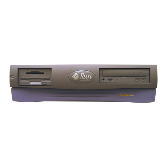
- Page 27 C H A P T E R Product Description The Sun Blade 150 workstation is a uniprocessor system that uses the UltraSPARC- IIi processor. shows the Sun Blade 150 workstation. FIGURE 1-1 This chapter contains the following topics: Section 1.1, “Product Overview” on page 1-3 Section 1.2, “Supported Sun Monitors”...
-
Page 28: Figure 1-1 Sun Blade 150 System
Sun Blade 150 System FIGURE 1-1 Sun Blade 150 Service Manual • June 2002... -
Page 29: Product Description
Product Overview The Sun Blade 150 system provides the following features: Desktop-style system enclosure Power supply: 250-watt CPU options: 550-MHz or 650-MHz UltraSPARC-IIi processor with 512-Kbyte internal cache, heatsink, and fan Hard drives: One 40 gigabyte, 7,200 RPM hard drive with ATA66 interface Additional hard drive available as an optional component Diskette drive: 1.44-megabyte (Mbyte) manual eject... -
Page 30: Supported Sun Monitors
24.1-inch LCD flat panel monitor Supports resolutions up to 1920x1200 System Description System components are housed in a desktop-style enclosure. Overall chassis dimensions for the Sun Blade 150 system are listed in TABLE 1-2 Sun Blade 150 System Physical Dimensions TABLE 1-2... -
Page 31: Figure 1-2 Front Panel Overview
Front Panel Overview FIGURE 1-2 1. Power switch 2. Power-indicator LED 3. Smart card reader 4. 3.5-inch diskette drive 5. 5.25-inch optical drive bay (CD-ROM or DVD-ROM) Back Panel Overview FIGURE 1-3 Chapter 1 Product Description... -
Page 32: Replaceable Components
Audio module line-out connector Audio module line-in connector Audio module microphone connector Replaceable Components This section lists the replaceable components for the Sun Blade 150 system. The numbered components in correlate to the numbered components listed in FIGURE 1-4 . Consult your authorized Sun sales representative or service provider to TABLE 1-4 confirm a part number before ordering a replacement part. -
Page 33: Figure 1-4 Sun Blade 150 System Replaceable Parts
Sun Blade 150 System Replaceable Parts FIGURE 1-4 Chapter 1 Product Description... -
Page 34: Table 1-4 Sun Blade 150 Replaceable Components
Diskette drive power cable Diskette drive power cable Diskette drive data cable diskette drive data cable Note – Consult your authorized Sun sales representative or service provider before ordering a replacement part. Sun Blade 150 Service Manual • June 2002... -
Page 35: Sunvts Overview
C H A P T E R SunVTS Overview This chapter contains an overview of the SunVTS™ diagnostic tool. This chapter contains the following topics: Section 2.1, “SunVTS Description” on page 2-1 Section 2.2, “SunVTS Requirements” on page 2-2 Section 2.3, “SunVTS References” on page 2-2 SunVTS Description SunVTS is an online Validation Test Suite. -
Page 36: Sunvts Requirements
Solaris that you are using and find the appropriate part number for the document. This collection is distributed on the Sun Computer Systems Supplement CD with each SPARC Solaris release and is also accessible at http://docs.sun.com. Sun Blade 150 Service Manual • June 2002... -
Page 37: Power-On Self-Test
C H A P T E R Power-On Self-Test This chapter describes how to initiate power-on self-test (POST) diagnostics. POST is a firmware program that can help determine if a portion of the system has failed. POST verifies the core functionality of the system, including operation the CPU, motherboard, memory, and some on-board I/O devices. -
Page 38: How To Use Post
Note – Both POST and OpenBOOT PROM on Sun Blade 150 systems report the CPU as an UltraSPARC IIe processor. The CPU in your system is an UltraSPARC IIi processor. How to Use POST When the workstation power is applied, POST runs automatically if both of the following conditions apply: The diag-switch? NVRAM parameter is set to true. -
Page 39: Setting Up A Tip Connection
A of the system you plan to test to another Sun workstation monitor or a TTY-type terminal. Note – There is a second serial port (serial port B) on the Sun Blade 150 system riser card. However, you will need a special connector and cable, and you will need an empty PCI card slot to access the serial port. -
Page 40: Disconnecting A Tip Connection
1. Open a terminal (shell) window. 2. Type eeprom. 3. Verify the following serial port default settings: tty-mode = 9600,8,n,1 Note – Ensure that the settings are consistent with TTY-type terminal or workstation monitor settings. Sun Blade 150 Service Manual • June 2002... -
Page 41: Viewing The Post Menus
Viewing the POST Menus To use the POST menus: 1. At the system prompt, type: ok% setenv diag-switch? true ok% setenv diag-level = menus Initializing POST POST can be initialized in two ways: maximum POST reporting, or max minimum POST reporting, or min Note –... -
Page 42: Maximum And Minimum Post Levels
This mode requires approximately two minutes to complete (with 128 Mbytes of DIMM installed). shows a typical serial port CODE EXAMPLE 3-1 POST output with diag-level set to max and a single 512 Mbyte DIMM installed. Sun Blade 150 Service Manual • June 2002... - Page 43 Note – Both POST and OpenBoot PROM report the CPU as an UltraSPARC IIe processor. The CPU in your system is an UltraSPARC IIi processor. Note – Video output is disabled while POST is initialized. diag-level Variable Set to max CODE EXAMPLE 3-1 Speed Jumper is set to 0000.0000.0000.0008 Hardware Power ON...
- Page 44 Ecache RAM Addr Test Ecache Tag Addr Test Ecache RAM Test Ecache Tag Test Memory Init Malloc Post Memory Memory Addr Check w/o Ecache Load Post In Memory Run POST from MEM Sun Blade 150 Service Manual • June 2002...
- Page 45 diag-level Variable Set to max (Continued) CODE EXAMPLE 3-1 ..Map PROM/STACK/NVRAM in DMMU Update Master Stack/Frame Pointers All FPU Basic Tests FPU Regs Test FPU Move Regs Test FPU State Reg Test FPU Functional Test FPU Trap Test All Basic IOMMU Tests PIO Decoder and BCT Test PCI Byte Enable Test CPU’s IOMMU Regs Test...
- Page 46 Write 0x55555555.55555555: ..............Read: ..............Write 0x00000000.00000000: ..............Read: ..............Info : 256MB at Dimm Slot 1 Start Addr: 0x00000000.40000000 Size: 256 MBytes Write 0xffffffff.ffffffff: ..............Read: ..............Write 0xaaaaaaaa.aaaaaaaa: ..............3-10 Sun Blade 150 Service Manual • June 2002...
- Page 47 diag-level Variable Set to max (Continued) CODE EXAMPLE 3-1 Read: ..............Write 0x55555555.55555555: ..............Read: ..............Write 0x00000000.00000000: ..............Read: ..............Info : 256MB at Dimm Slot 2 Start Addr: 0x00000000.80000000 Size: 256 MBytes Write 0xffffffff.ffffffff: ..............Read: ..............Write 0xaaaaaaaa.aaaaaaaa: ..............
- Page 48 ..............Read ..............Write 0xaaaaaaaa.aaaaaaaa ..............Read ..............Info : 256MB at Dimm Slot 1 Start Addr: 0x00000000.40000000 Size: 256 MBytes Write 0x33333333.33333333 ..............Read ..............Write 0x55555555.55555555 ..............Read ..............3-12 Sun Blade 150 Service Manual • June 2002...
- Page 49 diag-level Variable Set to max (Continued) CODE EXAMPLE 3-1 Write 0xcccccccc.cccccccc ..............Read ..............Write 0xaaaaaaaa.aaaaaaaa ..............Read ..............Info : 256MB at Dimm Slot 2 Start Addr: 0x00000000.80000000 Size: 256 MBytes Write 0x33333333.33333333 ..............Read ..............Write 0x55555555.55555555 ..............Read ..............
- Page 50 ..............Write 0xdddddddd.dddddddd ..............Read ..............Info : 256MB at Dimm Slot 1 Start Addr: 0x00000000.40000000 Size: 256 MBytes Write 0xa5a5a5a5.a5a5a5a5 ..............Read ..............Write 0x96969696.96969696 ..............Read ..............Write 0xbbbbbbbb.bbbbbbbb 3-14 Sun Blade 150 Service Manual • June 2002...
- Page 51 diag-level Variable Set to max (Continued) CODE EXAMPLE 3-1 ..............Read ..............Write 0xdddddddd.dddddddd ..............Read ..............Info : 256MB at Dimm Slot 2 Start Addr: 0x00000000.80000000 Size: 256 MBytes Write 0xa5a5a5a5.a5a5a5a5 ..............Read ..............Write 0x96969696.96969696 ..............Read ..............Write 0xbbbbbbbb.bbbbbbbb ..............
- Page 52 Loading onboard drivers: ebus flashprom eeprom idprom Probing Memory Bank #0 256 Megabytes Probing Memory Bank #1 256 Megabytes Probing Memory Bank #2 256 Megabytes Probing Memory Bank #3 256 Megabytes 3-16 Sun Blade 150 Service Manual • June 2002...
- Page 53 Probing /pci@1f,0/pci@5 Device 1 Nothing there Probing /pci@1f,0/pci@5 Device 2 Nothing there Sun Blade 150 (UltraSPARC-IIe 650MHz), Keyboard Present Copyright 1998-2002 Sun Microsystems, Inc. All rights reserved. OpenBoot 4.6, 1024 MB memory installed, Serial #51602330. Ethernet address 0:3:ba:13:63:9a, Host ID: 8313639a.
-
Page 54: Diag-Level Variable Set To Min
This mode requires approximately one minute to complete (with 128 Mbytes of DIMM installed). shows a serial port POST CODE EXAMPLE 3-2 output with diag-level set to min and a single 512 Mbyte DIMM installed. 3-18 Sun Blade 150 Service Manual • June 2002... - Page 55 CODE EXAMPLE 3-2 Speed Jumper is set to 0000.0000.0000.0008 Hardware Power ON @(#)OBP 4.6.0 2002/04/03 12:28 Executing Power On SelfTest @(#) Sun Blade 150 POST 2.0.1 05:13 PM on 04/23/02 Processor Module Identification UltraSPARC-IIe Version 1.3 Init POST BSS Init System BSS...
- Page 56 Update Master Stack/Frame Pointers All FPU Basic Tests FPU Regs Test FPU Move Regs Test All Basic IOMMU Tests CPU’s IOMMU Regs Test CPU’s IOMMU RAM Addr Test CPU’s IOMMU CAM Address Test 3-20 Sun Blade 150 Service Manual • June 2002...
- Page 57 diag-level Variable Set to min (Continued) CODE EXAMPLE 3-2 PBMA PCI Config Space Regs Test PBMA Control/Status Reg Test PBMA Diag Reg Test CPU’s IO Regs Test All Advanced CPU Tests IU ASI Access Test FPU ASI Access Test All CPU Error Reporting Tests CPU Data Access Trap Test CPU Addr Align Trap Test DMMU Access Priv Page Test...
- Page 58 Info : 256MB at Dimm Slot 2 Start Addr: 0x00000000.80000000 Size: 256 MBytes Write 0xffffffff.ffffffff: ..............Read: ..............Write 0xaaaaaaaa.aaaaaaaa: ..............Read: ..............Write 0x55555555.55555555: ..............Read: ..............Write 0x00000000.00000000: ..............Read: 3-22 Sun Blade 150 Service Manual • June 2002...
- Page 59 diag-level Variable Set to min (Continued) CODE EXAMPLE 3-2 ..............Info : 256MB at Dimm Slot 3 Start Addr: 0x00000000.c0000000 Size: 256 MBytes Write 0xffffffff.ffffffff: ..............Read: ..............Write 0xaaaaaaaa.aaaaaaaa: ..............Read: ..............Write 0x55555555.55555555: ..............Read: ..............Write 0x00000000.00000000: ..............
- Page 60 Probing /pci@1f,0 Device 13 SUNW,m64B Probing /pci@1f,0 Device 5 Probing /pci@1f,0/pci@5 Device 0 Nothing there Probing /pci@1f,0/pci@5 Device 1 Nothing there Probing /pci@1f,0/pci@5 Device 2 Nothing there Sun Blade 150 (UltraSPARC-IIe 650MHz), Keyboard Present 3-24 Sun Blade 150 Service Manual • June 2002...
-
Page 61: Post Progress And Error Reporting
Variable Set to min (Continued) CODE EXAMPLE 3-2 Copyright 1998-2002 Sun Microsystems, Inc. All rights reserved. OpenBoot 4.6, 1024 MB memory installed, Serial #51602330. Ethernet address 0:3:ba:13:63:9a, Host ID: 8313639a. POST Progress and Error Reporting POST progress indications are visible when a TTY-type terminal or a TIP line is connected between the serial port of the tested system and a second Sun workstation. - Page 62 MC3 = 0x00000000.a0000804 CPU MODULE upa_config is 0x0000003a.00000000 Ecache Tests Displacement Flush Ecache Ecache RAM Addr Test Ecache Tag Addr Test Ecache RAM Test Ecache Tag Test Memory Init Malloc Post Memory 3-26 Sun Blade 150 Service Manual • June 2002...
-
Page 63: Bypassing Post
Typical POST Error Message: DIMM Failure (Continued) CODE EXAMPLE 3-3 Memory Addr Check w/o Ecache *********************** STATUS =FAILED TEST =Memory Addr Check w/o Ecache SUSPECT=DIMM1 MESSAGE=Mem Addr line compare error addr 00000000.00000000 00000000.00000000 88880000.08000000 Bypassing POST At the system prompt, type: ok% setenv diag-level? off ok% setenv diag-switch? false Resetting Variables to Default Settings... -
Page 64: Viewing The Default Nvram Settings
2. Before replacing the motherboard, remove any optional components, such as PCI cards, then repeat the POST. Note – Nonoptional components such as DIMMs, the motherboard, the power supply, and the keyboard must be installed for POST to execute properly. 3-28 Sun Blade 150 Service Manual • June 2002... -
Page 65: Troubleshooting Procedures
C H A P T E R Troubleshooting Procedures This chapter describes how to troubleshoot possible hardware problems and suggests corrective actions. This chapter contains the following topics: Section 4.1, “Power-On Failure” on page 4-1 Section 4.2, “Video Output Failure” on page 4-2 Section 4.3, “Hard Drive, CD-ROM, or DVD-ROM Drive Failure”... -
Page 66: Video Output Failure
A hard drive read, write, or parity error is reported by the operating system or a customer application. A CD-ROM or DVD-ROM drive read error or parity error is reported by the operating system or a customer application. Sun Blade 150 Service Manual • June 2002... -
Page 67: Table 4-1 Internal Drives Identification
Action Replace the drive indicated by the failure message. The operating system identifies the internal drives as shown in TABLE 4-1 Internal Drives Identification TABLE 4-1 Operating Environment Drive Physical Location and Required Riser Board Address Target Cable Labels Connection Primary hard drive, Primary HDD IDE1, J504... -
Page 68: Power Supply Test
Verify voltage and signal availability as listed in Appendix B. 5. After you finish testing the power supply, remove the wrist strap, replace the system cover, and power on the system as described in Chapter 9 “Finishing Component Replacement.” Sun Blade 150 Service Manual • June 2002... -
Page 69: Dimm Failure
DIMM Failure At times, the operating environment, diagnostic program, or POST might not display a DIMM location (U number) as part of a memory error message. In this situation, the only available information is a physical memory address and failing byte (or bit). -
Page 70: Watch-Net And Watch-Net-All Diagnostics
CODE EXAMPLE 4-2 ok watch-net Internal loopback test -- succeeded. Link is -- up Looking for Ethernet Packets. ‘.’ is a Good Packet. ‘X’ is a Bad Packet. Type any key to stop............. Sun Blade 150 Service Manual • June 2002... -
Page 71: Probe-Ide Diagnostic
Watch-Net-All Diagnostic Output Message CODE EXAMPLE 4-3 ok watch-net-all /pci@1f,0/network@c,1 Internal loopback test -- succeeded. Link is -- up Looking for Ethernet Packets. ‘.’ is a Good Packet. ‘X’ is a Bad Packet. Type any key to stop............. 4.6.3 Probe-IDE Diagnostic The probe-IDE diagnostic transmits an inquiry command to internal and external IDE devices connected to the system’s on-board IDE interface. -
Page 72: Openboot Diagnostics
The OpenBoot Diagnostics menu interface is dynamically generated. The menu will appear different depending on how your Sun Blade 150 system is configured ( CODE EXAMPLE 4-5 Sun Blade 150 Service Manual • June 2002... -
Page 73: Starting The Openboot Diagnostics Menu
For example, if a keyboard is plugged into any of the four USB ports, the OpenBoot Diagnostics menu will display a test for that keyboard. If the system does not have a USB keyboard, no keyboard test will be available from the menu. OpenBoot Diagnostics Menu CODE EXAMPLE 4-5 _____________________________________________________________________________... - Page 74 Probing /pci@1f,0 Device 7 isa dma floppy parallel power serial serial Probing /pci@1f,0 Device c network firewire usb hub keyboard mouse storage storage Probing /pci@1f,0 Device 3 pmu i2c temperature card-reader dimm dimm 4-10 Sun Blade 150 Service Manual • June 2002...
- Page 75 Probing /pci@1f,0/pci@5 Device 2 Nothing there Probing /pci@1f,0 Device 13 SUNW,m64B Sun Blade 150 (UltraSPARC-IIe 650MHz), Keyboard Present Copyright 1998-2002 Sun Microsystems, Inc. All rights reserved. OpenBoot 4.6 build_10, 1024 MB memory installed, Serial #51271539. Ethernet address 0:3:ba:e:57:73, Host ID: 830e5773.
-
Page 76: Openboot Diagnostics Help
The help screen provides brief descriptions of each OpenBoot Diagnostics menu tool command as well as a listing of all NVRAM Configuration Variables which relate to OpenBoot Diagnostics. To view the help menu at the ok prompt, type: obdiag> help 4-12 Sun Blade 150 Service Manual • June 2002... -
Page 77: Specific Openboot Diagnostics Tests
OpenBoot Diagnostics Help Commands CODE EXAMPLE 4-8 obdiag> help obdiag commands exit Exit obdiag tool help Print this help information setenv Set diagnostic configuration variable to new value printenvs Print values for diagnostic configuration variables versions Print selftests, library and obdiag tool versions test-all Test all devices displayed in the menu test 1,2,5... -
Page 78: Test-All Command
Hit the spacebar to interrupt testing Testing /pci@1f,0/ebus@c ......passed Testing /pci@1f,0/firewire@c,2 ...... passed Testing /pci@1f,0/network@c,1 ....... passed Testing /pci@1f,0/isa@7/serial@0,3f8 ....passed Hit any key to return to the main menu 4-14 Sun Blade 150 Service Manual • June 2002... -
Page 79: Versions Command
3 firewire@c,2 1.23 xx/xx/xx Copyright (c) Sun Micro-systems, Inc. 4 flashprom@0,0 1.12 xx/xx/xx Copyright (c) Sun Micro-systems, Inc. 5 floppy@0,3f0 1.10 xx/xx/xx Copyright (c) Sun Microsystems, Inc. 6 ide@d 1.0 xx/xx/xx Copyright (c) Sun Micro-systems, Inc. 7 network@c,1 1.12 xx/xx/xx Copyright (c) Sun Micro-systems, Inc. -
Page 80: Printenvs Command
Hit any key to return to the main menu 4.7.4.8 Exit Command The exit command returns the user to the ok prompt and relinquishes control back to OpenBoot PROM. Exit Command CODE EXAMPLE 4-15 obdiag> exit 4-16 Sun Blade 150 Service Manual • June 2002... -
Page 81: Error Reporting In Openboot Diagnostics
CODE EXAMPLE 4-16 Testing /pci@1f,0/ebus@c/flashprom@0,0 ERROR : FLASHPROM CRC-32 is incorrect DEVICE : /pci@1f,0/ebus@c/flashprom@0,0 SUBTEST: selftest MACHINE: Sun Blade 150 (UltraSPARC-IIe) SERIAL#: 11910854 DATE : 04/10/2002 02:32:16 GMT /pci@1f,0/ebus@c/flashprom@0,0 selftest failed, return code 4.7.6 Exiting OpenBoot Diagnostics and Resetting the... - Page 82 Note – If you do not need to save any custom changes to OpenBoot PROM, you could use the set-defaults parameter instead of the reset-all parameter. See Section 3.9, “Resetting Variables to Default Settings” on page 3-27.) 4-18 Sun Blade 150 Service Manual • June 2002...
-
Page 83: Preparing For Component Removal And Replacement
C H A P T E R Preparing for Component Removal and Replacement This chapter describes the activities you must do to prepare for removal and replacement of internal system components. Note – It is very important that you review the safety requirements, symbols, and precautions in this chapter before you begin to remove or replace system components. -
Page 84: Safety Symbols
Follow all safety precautions. 5.3.1 Modification to Equipment Caution – Do not make mechanical or electrical modifications to the equipment. Sun Microsystems is not responsible for regulatory compliance of a modified Sun product. Sun Blade 150 Service Manual • June 2002... -
Page 85: Placement Of A Sun Product
5.3.2 Placement of a Sun Product Caution – To ensure reliable operation of the Sun product and to protect it from overheating, ensure equipment openings are not blocked or covered. Never place a Sun product near a radiator or hot air register. 5.3.3 Power Cord Connection Caution –... -
Page 86: Lithium Battery
Do not dispose of a battery in fire. Do not disassemble a battery or attempt to recharge it. Tools Required The following tools are required to service the Sun Blade 150 system. No. 2 Phillips screwdriver (magnetized tip suggested) Needle-nose pliers... -
Page 87: Figure 5-1 Front Panel Power Switch
Momentarily press and release the front panel power switch ( ) to FIGURE 5-1 automatically shut down all programs, the operating system, and power off the system. From the system shutdown menu displayed on the monitor, select “Shutdown.” If Solaris is not running in a windowing environment: Press and hold the front panel power switch ( ) for four seconds to FIGURE 5-1... -
Page 88: Removing The System Cover
2. Peel the liner from the copper foil at the opposite end of the wrist strap. 3. Attach the copper end of the wrist strap to the chassis ( FIGURE 5-3 Sun Blade 150 Service Manual • June 2002... -
Page 89: Figure 5-3 Attaching The Wrist Strap To The Chassis
4. Disconnect the AC power cord from the system. Copper end Attaching the Wrist Strap to the Chassis FIGURE 5-3 Chapter 5 Preparing for Component Removal and Replacement... - Page 90 Sun Blade 150 Service Manual • June 2002...
-
Page 91: Removing And Replacing Major Subassemblies
C H A P T E R Removing and Replacing Major Subassemblies This chapter describes how to remove and replace the major subassemblies. This chapter contains the following topics: Section 6.1, “Power Supply” on page 6-1 Section 6.2, “Cable Assemblies” on page 6-3 Section 6.3, “Speaker Assembly”... -
Page 92: Replacing The Power Supply
4. Connect the power cable connector to the riser board connector J501. 5. Connect the power cable connector from riser board connector J505. 6. Detach the wrist strap, replace the system cover, and power on the system as described in Chapter 9. Sun Blade 150 Service Manual • June 2002... -
Page 93: Cable Assemblies
Cable Assemblies The following cable assemblies can be removed and replaced: Diskette drive cable assembly Diskette drive power cable assembly Primary IDE cable assembly Secondary IDE cable assembly Smart card reader cable assembly Power switch/LED assembly Note – All system cable assemblies are part of a cable kit; they cannot be ordered separately. -
Page 94: Replacing The Diskette Drive Data Cable Assembly
4. If you moved the fan assembly, replace it. See “Replacing the Fan Assembly” on page 6-16. 5. Detach the wrist strap, replace the system cover, and power on the system as described in Chapter 9. Sun Blade 150 Service Manual • June 2002... -
Page 95: Removing The Diskette Drive Power Cable Assembly
6.2.3 Removing the Diskette Drive Power Cable Assembly 1. Power off the system, remove the system cover, and attach an antistatic wrist strap as described in Chapter 5. Caution – Use proper ESD grounding techniques when handling components. Wear an antistatic wrist strap and use an antistatic mat. Store ESD-sensitive components in antistatic bags before placing them on any surface. -
Page 96: Replacing The Diskette Drive Power Cable Assembly
2. Disconnect the primary IDE cable assembly connectors from the following FIGURE 6-4 CD-ROM or DVD-ROM drive Primary hard drive Riser board (J504 is also labeled IDE1) 3. Remove the primary IDE cable assembly from the chassis. Sun Blade 150 Service Manual • June 2002... -
Page 97: Replacing The Primary Ide Cable Assembly
CD-DVD-ROM connector IDE 1 (J504) Removing and Replacing the Primary IDE Cable Assembly FIGURE 6-4 6.2.6 Replacing the Primary IDE Cable Assembly 1. Position the primary IDE cable assembly into the chassis ( FIGURE 6-4 2. Connect the primary IDE cable assembly connectors to the following: Primary hard drive CD-ROM or DVD-ROM drive Riser board (J504 is also labeled IDE1) -
Page 98: Replacing The Secondary Ide Cable Assembly
2. Connect the secondary IDE cable assembly connectors to the following: Secondary hard drive Riser board (J503 is also labeled IDE2) Note – Ensure that the cable assembly connectors are properly oriented by aligning the connector keys. Sun Blade 150 Service Manual • June 2002... -
Page 99: Removing The Smart Card Reader Cable Assembly
3. Detach the wrist strap, replace the system cover, and power on the system as described in Chapter 9. 6.2.9 Removing the Smart Card Reader Cable Assembly 1. Power off the system, remove the system cover, and attach an antistatic wrist strap as described in Chapter 5. -
Page 100: Replacing The Smart Card Reader Cable Assembly
Store ESD-sensitive components in antistatic bags before placing them on any surface. 2. Remove the front panel bezel by lifting the three tabs and gently lifting the bezel from the system ( FIGURE 6-7 6-10 Sun Blade 150 Service Manual • June 2002... -
Page 101: Figure 6-7 Removing The Front Bezel
Removing the Front Bezel FIGURE 6-7 3. If any long PCI cards are installed, remove them. See Section 8.4.1, “Removing a PCI Card” on page 8-10. 4. Move the peripheral assembly aside to provide clearance: a. Open the cable routing clip below the peripheral assembly. This will release the tension from the smart card and diskette drive cables. -
Page 102: Replacing The Power Switch/Led Assembly
2. Attach the power switch to the chassis with the washer and nut. 3. Press the LED into the chassis from the rear of the front panel. 4. Route the cable along the chassis. 6-12 Sun Blade 150 Service Manual • June 2002... -
Page 103: Speaker Assembly
5. Close the cable routing clips. 6. Connect the cable connector to riser board connector J2. 7. If you moved the fan assembly, replace it. See Section 6.4.2, “Replacing the Fan Assembly” on page 6-16. 8. Replace the peripheral assembly: a. -
Page 104: Figure 6-9 Removing And Replacing The Speaker Assembly
5. Disconnect the speaker cable from connector J12 on the riser board. 6. Press the speaker retaining tab on the chassis front panel. 7. Remove the speaker assembly from the chassis. J12 connector Removing and Replacing the Speaker Assembly FIGURE 6-9 6-14 Sun Blade 150 Service Manual • June 2002... -
Page 105: Replacing The Speaker Assembly
6.3.2 Replacing the Speaker Assembly 1. Position the speaker assembly into the chassis ( FIGURE 6-9 2. Grasp the speaker and press the speaker into the three chassis speaker slots. 3. Route the speaker cable and any other loose cables through the cable retaining clip. -
Page 106: Replacing The Fan Assembly
Replacing the Fan Assembly 1. Position the fan assembly, ensuring that the fan retaining tabs are aligned with the chassis retaining slots ( FIGURE 6-10 2. Press the fan assembly into the chassis slots. 6-16 Sun Blade 150 Service Manual • June 2002... - Page 107 3. Connect the fan assembly power cable connector to the riser board (J4). 4. Route the cables through the cable retaining clip and close the clip. 5. If you removed any long PCI cards, replace the PCI cards into the riser board. See Section 8.4.2, “Replacing a PCI Card”...
- Page 108 6-18 Sun Blade 150 Service Manual • June 2002...
-
Page 109: Removing And Replacing Storage Devices
C H A P T E R Removing and Replacing Storage Devices This chapter describes how to remove and replace the Sun Blade 150 storage devices. This chapter contains the following topics: Section 7.1, “Diskette Drive” on page 7-1 Section 7.2, “Smart Card Reader” on page 7-4 Section 7.3, “Hard Drives”... -
Page 110: Figure 7-1 Removing And Replacing The Peripheral Assembly
6. Slide the peripheral assembly to the rear of the chassis and lift it from the chassis. 7. Using a No. 2 Phillips screwdriver, remove the three screws securing the diskette drive to the peripheral assembly. 8. Remove the diskette drive from the peripheral assembly ( FIGURE 7-2 Sun Blade 150 Service Manual • June 2002... -
Page 111: Replacing The Diskette Drive
Removing the Diskette Drive FIGURE 7-2 7.1.2 Replacing the Diskette Drive 1. Position the diskette drive into the peripheral assembly ( FIGURE 7-2 2. Using a No. 2 Phillips screwdriver, replace the three screws securing the diskette drive to the peripheral assembly. 3. -
Page 112: Smart Card Reader
6. Slide the peripheral assembly to the rear of the chassis and lift it from the chassis. 7. Using a No. 2 Phillips screwdriver, remove the three screws securing the smart card reader to the peripheral assembly ( FIGURE 7-3 Sun Blade 150 Service Manual • June 2002... -
Page 113: Replacing The Smart Card Reader
Removing and Replacing the Smart Card Reader FIGURE 7-3 8. Remove the smart card reader from the peripheral assembly. 7.2.2 Replacing the Smart Card Reader 1. Slide the smart card reader into the peripheral assembly. 2. Using a No. 2 Phillips screwdriver, replace the three screws securing the smart card reader to the peripheral assembly ( FIGURE 7-3 3. -
Page 114: Hard Drives
6. Turn the hard drive tray over and place it on an antistatic mat. 7. Using a No. 2 Phillips screwdriver, remove the four screws securing the hard drive to the hard drive tray. 8. Lift the hard drive tray from the hard drive. Sun Blade 150 Service Manual • June 2002... -
Page 115: Replacing A Primary Hard Drive
CD/DVD-ROM drive IDE cable connector IDE 1 Removing and Replacing a Primary Hard Drive FIGURE 7-4 7.3.2 Replacing a Primary Hard Drive Note – Read the hard drive product guide for information about jumpers, switch settings, or other installation tasks. Note –... -
Page 116: Installing A Secondary Hard Drive
2. Lift the spring-loaded latch upward to release the hard drive tray from the chassis FIGURE 7-5 3. Pull the hard drive tray ejection lever away from the chassis. 4. Disconnect the existing hard drive IDE and power cables from the primary hard drive. Sun Blade 150 Service Manual • June 2002... - Page 117 5. Slide the hard drive tray out of the chassis. 6. Place the new secondary hard drive onto the hard drive tray. 7. Turn the tray upside down on an antistatic mat. Note – Before installing the hard drive into the system, verify that the drive’s back- panel mode-select jumper is set to “CS,”...
- Page 118 FIGURE 7-5). 12. Connect the hard drive IDE cable connector labeled Primary HDD to the primary hard drive. 13. Connect the power cable to the secondary hard drive ( FIGURE 7-6 7-10 Sun Blade 150 Service Manual • June 2002...
-
Page 119: Cd-Rom Or Dvd-Rom Drive
14. Connect the power cable to the primary hard drive. 15. Connect the secondary hard drive to the cable connector labeled Secondary HDD. The following diagram shows the cabling for the secondary hard drive. IDE2 (J503) Secondary HDD Power cable Secondary Hard Drive Cabling Configuration FIGURE 7-6 Caution –... -
Page 120: Replacing A Cd-Rom Or Dvd-Rom Drive
Replacing a CD-ROM or DVD-ROM Drive Note – Before you replace the CD-ROM or DVD-ROM drive, verify that the drive back panel mode-select jumper is set to “CS,” “Enable Cable Select,” or “Cable Select.” 7-12 Sun Blade 150 Service Manual • June 2002... - Page 121 1. Position the CD-ROM or DVD-ROM drive in the chassis ( FIGURE 7-7 2. Push the CD-ROM or DVD-ROM drive toward the chassis rear. 3. Connect the following to the rear of the CD-ROM or DVD-ROM drive: CD-ROM or DVD-ROM drive cable connector Power cable connector Note –...
- Page 122 7-14 Sun Blade 150 Service Manual • June 2002...
-
Page 123: Removing And Replacing The Motherboard And Related Components
C H A P T E R Removing and Replacing the Motherboard and Related Components This chapter describes how to remove and replace the Sun Blade 150 motherboard and motherboard components. This chapter contains the following topics: Section 8.1, “CPU” on page 8-1 Section 8.2, “NVRAM/TOD”... - Page 124 9. Gently lift the CPU from the socket. If the CPU does not lift off easily, ensure that the locking lever is fully released. 10. Place the CPU on an antistatic mat with the pins facing up. Sun Blade 150 Service Manual • June 2002...
-
Page 125: Replacing The Cpu
CPU locking lever Heatsink Fan power cable CPU Key Grounding ring legs Heatsink retaining clip CPU socket* *The CPU socket is permanently attached to the motherboard Removing and Replacing the CPU FIGURE 8-1 8.1.2 Replacing the CPU 1. Position the CPU over the motherboard CPU socket ( FIGURE 8-1 Caution –... -
Page 126: Figure 8-2 Jp3 Openboot Prom Jumper Settings For 650 Mhz And 550 Mhz Cpus
650 MHz and 550 MHz CPUs. FIGURE 8-2 Motherboard jumper JP3 550 MHz CPU 650 MHz CPU JP3 OpenBoot PROM Jumper Settings for 650 MHz and 550 MHz CPUs FIGURE 8-2 Sun Blade 150 Service Manual • June 2002... -
Page 127: Nvram/Tod
Caution – Be sure that you set the jumpers correctly before powering-on the system. A 550 MHz CPU can not operate if the jumpers are set for 650 MHz. A 650 MHz CPU will operate at 550 MHz if the jumpers are set for 550 MHz. 11. -
Page 128: Replacing The Nvram/Tod
2. Replace any PCI card(s) removed from slots 1 and 3. See Section 8.4.2, “Replacing a PCI Card” on page 8-11. 3. Detach the wrist strap, replace the system cover, and power on the system as described in Chapter 9. Sun Blade 150 Service Manual • June 2002... -
Page 129: Dimms
DIMMs Caution – For maximum performance, the DIMMs in this system have been specifically designed for it. Do not use DIMMs from a different system to upgrade or replace the DIMMs in this system. Verify with your Sun sales or service representative that the DIMMs you order have been Sun-certified for this system. -
Page 130: Figure 8-4 Dimm Installation Order
3. Push the ejection levers at each end of the DIMM connector away from the DIMM FIGURE 8-5 4. Lift the DIMM straight up from the motherboard connector. 5. Place the DIMM on an antistatic mat. Sun Blade 150 Service Manual • June 2002... -
Page 131: Replacing A Dimm
Ejection lever Removing and Replacing a DIMM FIGURE 8-5 8.3.2 Replacing a DIMM Caution – Do not remove any DIMM from the antistatic container until you are ready to install it on the motherboard. Handle DIMMs only by their edges. Do not touch DIMM components or metal parts. -
Page 132: Pci Card
5. If you are removing a long PCI card, slide back the retractable card guide to release the card. Caution – To avoid damaging the card’s connector, do not apply force to only one end or one side of the card. 8-10 Sun Blade 150 Service Manual • June 2002... -
Page 133: Replacing A Pci Card
6. Grasp the two corners of the PCI card and pull the card straight out from the riser board connector. 7. Place the PCI card on an antistatic mat. PCI card bracket retainer Detent Retractable card guide Removing and Replacing a PCI Card FIGURE 8-6 8.4.2 Replacing a PCI Card... -
Page 134: Motherboard
2. Pull the motherboard ejection lever away from the chassis to release the motherboard from the riser board connector ( FIGURE 8-7 3. Slide the motherboard out of the chassis. 8-12 Sun Blade 150 Service Manual • June 2002... - Page 135 4. Place the motherboard on an antistatic mat. 5. Remove the following from the motherboard: CPU module See Section 8.1.1, “Removing the CPU” on page 8-1. NVRAM/TOD with carrier See Section 8.2.1, “Removing the NVRAM/TOD” on page 8-5. DIMMs See Section 8.3.1, “Removing a DIMM” on page 8-7. Note –...
-
Page 136: Replacing The Motherboard
Caution – Handle the motherboard by the back panel or the edges only. Note – If you will re-install the same motherboard you do not need to change the CPU speed setting jumpers or the Flash PROM jumpers. 8-14 Sun Blade 150 Service Manual • June 2002... -
Page 137: Figure 8-8 Jp1/Jp2 Jumper Settings For The Flash Prom
1. Using needle-nosed pliers, set the Flash PROM Jumpers, JP1 and JP2. Flash PROM jumpers JP1 and JP2 are used for reprogramming specific code blocks and remote programming of the flash PROM. illustrates the default FIGURE 8-8 JP1/JP2 jumper settings for the flash PROM. identifies the flash PROM TABLE 8-1 jumper settings. -
Page 138: Riser Board
See Section 8.5.1, “Removing the Motherboard” on page 8-12. 5. Using a No. 2 Phillips screwdriver, remove the three screws securing the riser board to the system chassis ( FIGURE 8-9 6. Remove the riser board from the chassis. 8-16 Sun Blade 150 Service Manual • June 2002... -
Page 139: Replacing The Riser Board
Screws (3) Removing and Replacing the Riser Board FIGURE 8-9 8.6.2 Replacing the Riser Board 1. Position the riser board into the chassis ( FIGURE 8-9 The riser board fits between the staggered tabs on the chassis. 2. Using a No. 2 Phillips screwdriver, replace the three screws securing the riser board to the system chassis. - Page 140 8-18 Sun Blade 150 Service Manual • June 2002...
-
Page 141: Finishing Component Replacement
C H A P T E R Finishing Component Replacement This chapter contains the following topics: Section 9.1, “Replacing the System Cover” on page 9-1 Section 9.2, “Powering On the System” on page 9-2 Replacing the System Cover 1. Remove the wrist strap from the system chassis and from your wrist. 2. -
Page 142: Powering On The System
2. Reconnect and turn on power to any peripherals (so that the system can recognize the peripherals when it is powered on). 3. Press the front panel power switch ( FIGURE 9-2 Power switch System Power Switch FIGURE 9-2 4. Verify the following: Sun Blade 150 Service Manual • June 2002... - Page 143 a. The front panel power indicator LED is on. b. The system fans are spinning. 5. If the system does not power on, see the Troubleshooting section in the Getting Started Guide. Chapter 9 Finishing Component Replacement...
- Page 144 Sun Blade 150 Service Manual • June 2002...
-
Page 145: Openboot Emergency Procedures
C H A P T E R OpenBoot Emergency Procedures The introduction of USB keyboards has made it necessary to change the Stop-N, Stop-D, and Stop-F commands. The following sections describe the OpenBoot emergency procedures for systems with standard keyboards and for newer systems with USB keyboards. -
Page 146: Openboot Emergency Procedures For Systems With Usb Keyboards
NVRAM contents to the default values. If a screen similar to the following is not displayed, repeat Steps 1 and 2. Note – Both POST and OpenBOOT PROM on Sun Blade 150 systems report the CPU as an UltraSPARC IIe processor. The CPU in your system is an UltraSPARC IIi processor. -
Page 147: Stop-F Functionality
Resetting Default NVRAM Variables (Continued) CODE EXAMPLE 10-1 ’use-nvramrc?’ is false ’input-device’, ’output-device’ are defaulted ’ttya-mode’, ’ttyb-mode’ are defaulted These changes are temporary and the original values will be restored after the next hardware or software reset. Some NVRAM configuration parameters are reset to their defaults. The defaults include parameters that are more likely to cause problems, such as TTYA settings. -
Page 148: Stop-D Functionality
(see Section 10.2.2, “Stop-N Equivalent Functionality” on page 10-2), since this temporarily sets diag-switch? to true. If you want to turn on the diagnostic mode permanently, type: ok setenv diag-switch? true 10-4 Sun Blade 150 Service Manual • June 2002... -
Page 149: Product Specifications And Reference Information
A P P E N D I X Product Specifications and Reference Information This appendix provides product specifications for the Sun Blade 150 system. Section A.1, “Physical Specifications” on page A-1 Section A.2, “Electrical Specifications” on page A-2 Section A.6, “Modem Setup Specifications” on page A-6 Section A.4, “Environmental Requirements”... -
Page 150: Electrical Specifications
±5% +5 VSB +5 VSB is a standby voltage that is always present when AC line voltage is present. Acoustic Specifications Table lists the acoustic specifications for the Sun Blade 150 system. Acoustic Specifications TABLE A-3 System Status Acoustic Range Operating <42 dba to 55 dba... -
Page 151: Environmental Requirements
Environmental Requirements The following table lists environmental requirements for the Sun Blade 150 system. Sun Blade 150 System Environmental Requirements TABLE A-4 Environmental Operating Nonoperating Temperature 41 to 95 degrees F -4 to 140 degrees F (5 to 35 degrees C) -
Page 152: Reference Information
Section A.5.3, “CD Handling and Use” on page A-5 A.5.1 IDE Cabling Configuration shows the IDE cabling. The Sun Blade 150 system can support an FIGURE A-2 optional secondary hard drive. An optional cable with two connectors is shipped with the secondary drive and is connected as shown in FIGURE A-2. - Page 153 A.5.2 CD-ROM and DVD-ROM Jumper Settings Before you install a CD-ROM or DVD-ROM drive or a hard drive in a Sun Blade 150 system, verify that the drive’s back panel mode-select jumper is set as follows: Set the CD-ROM drive jumper (located on the CD-ROM drive back panel) to either “CS,”...
-
Page 154: Ejecting A Cd From The Cd-Rom Or Dvd-Rom Drive
Store CDs in storage boxes so that they remain clean and free of dust. Modem Setup Specifications Section A.6.1, “Setting Up the Modem” on page A-7 Section A.6.2, “Changing the Serial Port Speed” on page A-8 Section A.6.3, “Modem Recommendations” on page A-9 Sun Blade 150 Service Manual • June 2002... -
Page 155: Setting Up The Modem
A.6.1 Setting Up the Modem Any modem that is compatible with CCITT V.24 can be connected to one of the system serial ports. Internal serial port: Riser board J13 External serial port External and Internal Serial Ports FIGURE A-3 Modems can be set up to function in one of three ways: Dial-out only Dial-in only Bidirectional... -
Page 156: Changing The Serial Port Speed
The device name is the serial port name—for example, /dev/tty[a,b] or /dev/term/[a,b]. 4. Press Esc and Shift-colon, then type wq to save your file change(s) and to exit from the vi text editor. Sun Blade 150 Service Manual • June 2002... -
Page 157: Modem Recommendations
A.6.3 Modem Recommendations A.6.3.1 Cable For a modem-to-host (system) connection, use an RS-423/RS-232 straight-through cable with DB-25 male connectors at both ends. A.6.3.2 Modem Switch Settings (AT Commands) Note – These settings are guidelines only. These guidelines might change depending on site requirements and the chosen modem. Enable transmit flow control (AT&H1) [suggested setting] Required for sending binary/8-bit data. - Page 158 A-10 Sun Blade 150 Service Manual • June 2002...
-
Page 159: Signal Descriptions
A P P E N D I X Signal Descriptions This appendix describes the Sun Blade 150 motherboard connector signals and pin assignments. Section B.1, “Power Supply Connectors” on page B-2 Section B.2, “Universal Serial Bus Connector” on page B-4 Section B.3, “IEEE 1394 Connector”... -
Page 160: Power Supply Connectors
Power Supply Connectors There are two power supply connectors on the riser board. The Sun Blade 150 riser board uses a standard ATX style connector at (J501) and a connector at J505. Power Supply Connector J501 Pin Configuration FIGURE B-1... -
Page 161: Figure B-2 Secondary Power Supply Connector J505 Pin Configuration
Power Supply Connector J501 Pin Assignments (Continued) TABLE B-1 Signal Description Open +5 VDC +5 VDC / sense Pin 8 Pin 1 Secondary Power Supply Connector J505 Pin Configuration FIGURE B-2 Power Supply Connector J505 Pin Assignments TABLE B-2 Signal Description +3.3V +3.3 VDC... -
Page 162: Universal Serial Bus Connector
Sun USB Type-6 keyboard and the USB mouse. USB Connector J17, J18 Pin Configuration FIGURE B-3 USB Connector J17, J18 Pin Assignments TABLE B-3 Signal Name USB0_VCC CM_USB_D0_N CM_USB_D0_P USB1_VCC CM_USB_D1_N CM_USB_D1_P Sun Blade 150 Service Manual • June 2002... -
Page 163: Ieee 1394 Connector
IEEE 1394 Connector Two IEEE 1394 connectors are located on the back panel. IEEE 1394 Connector J20, J30 Pin Configuration FIGURE B-4 IEEE 1394 Connector J20, J30 Pin Assignments TABLE B-4 Signal Name Description P1394_EX_BUSPOWER Bus power Ground CM_P1394_TPB1_OUT_N CM_P1394_TPB1_OUT_P CM_P1394_TPA1_OUT_N CM_P1394_TPA1_OUT_P Appendix B Signal Descriptions... -
Page 164: Twisted-Pair Ethernet Connector
Transmit data + tpe1 Transmit data - tpe2 Receive data + Common mode termination Termination Common mode termination Termination tpe3 Receive data - Common mode termination Termination Common mode termination Termination Sun Blade 150 Service Manual • June 2002... -
Page 165: Tpe Cable-Type Connectivity
B.4.1 TPE Cable-Type Connectivity The following types of TPE cables can be connected to the TPE connector: For 10BASE-T applications, unshielded twisted-pair (UTP) cable: Category 3 (UTP-3, “voice grade”) Category 4 (UTP-4) Category 5 (UTP-5, “data grade”) For 100BASE-T applications, UTP cable, UTP-5, “data grade” B.4.2 External UTP-5 Cable Lengths TPE UTP-5 Cables... -
Page 166: Serial Port Connector
You also need to use a PCI card slot to access the serial port connector on the riser board. shows how you can access the riser FIGURE B-8 card serial port through a PCI card slot. Sun Blade 150 Service Manual • June 2002... -
Page 167: Figure B-7 Riser Board Serial Port Pinouts (J13
(Pin 2) (Pin 9) (Pin 1) Riser Board Serial Port Pinouts (J13) FIGURE B-7 Riser Board Serial Port Connector J13 Pin Assignments TABLE B-8 Signal Description Carrier detect Data set ready Receive Data Request to send Transmit data Clear to send Data terminal ready Ring indicator Ground... -
Page 168: Figure B-8 Accessing The Second Serial Port Through A Pci Card Slot
Accessing the Second Serial Port Through a PCI Card Slot FIGURE B-8 Some third-party cables are too bulky to fit the Sun Blade 150 serial port and video port. The Sun Blade 150 system was shipped with connector extensions to allow for... -
Page 169: Figure B-9 Serial And Video Port Connector Extensions
Serial and Video Port Connector Extensions FIGURE B-9 Appendix B Signal Descriptions B-11... -
Page 170: Parallel Port Connector
Set low by the peripheral device to indicate an error during forward channel transfer. In reverse channel transfer, set low to indicate peripheral device has data ready to send to the host. Used to send Data0 and Data4. B-12 Sun Blade 150 Service Manual • June 2002... - Page 171 Parallel Port Connector J9 Pin Assignments (Continued) TABLE B-9 Signal Description INIT_L Driven low by the host to reset peripheral. PAR_IN_L Set low by the host to select peripheral device for forward channel transfer. Set high to indicate bus direction is from peripheral to host.
-
Page 172: Audio Connectors
Audio Connector Line Assignment TABLE B-10 Component Headphones Line-Out Line-In Microphone Left channel Left channel Left channel Left channel Ring (center) Right channel Right channel Right channel Right channel Shield Ground Ground Ground Ground B-14 Sun Blade 150 Service Manual • June 2002... -
Page 173: Video Connector
Video Connector The video connector is a 15-pin mini D-sub connector located on the back panel. Video Connector J37 Pin Configuration FIGURE B-12 Video Connector J37 Pin Assignments TABLE B-11 Signal Description Red video signal Green Green video signal Blue Blue video signal Ground Not connected... - Page 174 Some third-party cables are too bulky to fit the Sun Blade 150 serial port and video port. The Sun Blade 150 system was shipped with connector extensions to allow for better connections with bulky third-party cables. See FIGURE B-13 Serial and Video Port Connector Extensions...
-
Page 175: Functional Description
A P P E N D I X Functional Description This appendix provides a functional description of the Sun Blade 150 system. Section C.1, “System” on page C-1 Section C.2, “Motherboard” on page C-3 Section C.3, “Riser Board” on page C-4 Section C.4, “Jumper Descriptions”... - Page 176 PCIO-2 ASIC Interface Parallel Serial Diskette Port Port Drive Line out Flash Line in PROM 1394 SVGA Ethernet Headphone 10/100 OpenBoot SDRAM RJ-45 PROM Sun Blade 150 System Functional Block Diagram FIGURE C-1 Sun Blade 150 Service Manual • June 2002...
-
Page 177: Motherboard
Motherboard The following figure illustrates a layout diagram of the system motherboard. Logical Connect DIMM installation order Ethernet LED Flashing = 100 Mbps Not flashing = 10 Mbps Motherboard Layout Diagram FIGURE C-2 Appendix C Functional Description... -
Page 178: Riser Board
Description PCI connector Power/LED connector PCI connector Fan connector PCI connector Debug connector Debug connector Smart card connector Diskette drive data connector Diskette drive power connector Speaker connector (Second) Serial Port Connector Sun Blade 150 Service Manual • June 2002... -
Page 179: Jumper Descriptions
J501 J502 J505 J504 IDE 1 J503 IDE 2 Riser Board Layout Diagram, Side 2 FIGURE C-4 Riser Board Connectors, Side 2 TABLE C-2 Connector Description J501 Power supply connector J502 IDE drive power connector J503 Secondary IDE channel connector J504 Primary IDE channel connector Jumper Descriptions... -
Page 180: Motherboard Components
Motherboard Components This section describes all the Sun Blade 150 system components. Most of the devices are connected through the PCI interface that is supported by the CPU. The CPU has one 32-bit 33 MHz PCI bus. The PCI bus from the CPU is 3.3V. All the PCI devices on the motherboard are 3.3V devices. -
Page 181: Ichip2 Asic
The ASIC also supports three types of interrupts: level high, level low, and pulse low. C.5.3 SouthBridge ASIC The Sun Blade 150 system uses the SouthBridge ASIC, which is a highly integrated system I/O chip set in a 328-pin, ball grid array (BGA) package. It has the following integrations: PCI-to-ISA bridge... - Page 182 Floppy Drive Controller The floppy drive controller (FDC) is software compatible with 82077 and supports 16-byte data FIFOs. The interface supports standard 1 Mbit/sec, 500 Kbit/sec, 300 Kbit/sec, 250 Kbit/sec data transfer rates. Sun Blade 150 Service Manual • June 2002...
-
Page 183: Pci Ide Controller
C.5.3.2 PCI IDE Controller There are two IDE channels within the IDE controller to support up to four devices. Each channel can operate at DMA mode 4 speed independently. The target devices are one or two UltraDMA/66 capable hard drives and a DVD-ROM or CD-ROM drive. -
Page 184: Smbus Interface
SMBus Interface The SMBus host controller provides the communication channel with other serial devices through SMBus protocol. In the Sun Blade 150 system, this SMBus is connected to the four SDRAM DIMM modules, so that on system power-up OpenBoot PROM can access the information regarding each DIMM type and configuration stored inside the serial EEPROM on each DIMM module. -
Page 185: Usb
OpenHCI host controller 1.5 and 12 Mb/s transfer rate Four host ports The Sun Blade 150 uses two USB ports for the keyboard and mouse. See Appendix E for details. C.5.5.3 IEEE 1394 The Sun Blade 150 provides a dual IEEE-1394 interface for faster asynchronous peripheral devices of transfer rate up to 400Mb/s. -
Page 186: Smart Card Interface
PCB to the connector of the riser board. The smart card connects to the on-board I2C (SMBus) interface on the SouthBridge ASIC. +12V I2C_CLK_L I2C_DATA_L SC_INT_L Smart Card Interface Header FIGURE C-8 C-12 Sun Blade 150 Service Manual • June 2002... -
Page 187: Nvram/Tod
Clocking C.7.1 Clock Generation The four clock domains in the Sun Blade 150 system. The domains are the CPU, SDRAM, PCI, and miscellaneous clocks. All the clocks in those four domains are generated from clock synthesizers or dedicated crystals on the motherboard except SDRAM clocks, which are generated by the CPU. -
Page 188: Openboot Prom Jumpers Cpu Speed Selection
MC12429 accordingly through the OpenBoot PROM serial programming interface. The CPU speeds and jumper settings are provided in the CPU release notes. shows the jumper settings for the 550 MHz and 650 MHz CPUs. FIGURE C-9 C-14 Sun Blade 150 Service Manual • June 2002... -
Page 189: Power Control
FIGURE C-9 Power Control C.8.1 Power Switch The Sun Blade 150 system power on/off switch is on the front panel. For more information see the sections below and Chapter 10, “OpenBoot Emergency Procedures” on page 10-1. C.8.1.1 Powering on the System When the system is off, you can power on the system by pushing the power switch. -
Page 190: Forcing The System To Power-Off During Software Hang
VRM ID codes from the CPU are not used. The 1.7 V code required for the processor is hard set. Voltage changes are possible but require installation of special header/jumper connections. C-16 Sun Blade 150 Service Manual • June 2002... -
Page 191: On-Board Vrm Requirements
LED and causes the LED to blink at the rate of 1Hz or 2Hz. C.8.4 Optional Secondary Hard Drive The Sun Blade 150 system has a provision for a second hard drive on the hard drive tray ( FIGURE C-10... -
Page 192: Memory Architecture
The memory controller only supports 4 Gbytes of space. Note – Although the cache and memory controller support up to 4 Gbytes, only 512 MB DIMMS are supported on the Sun Blade 150 system. This limits the maximum DIMM configuration to 2 Gbytes. - Page 193 WE[0,1] SCLK_OUT IO_SCLK MD[],ECC[], ECC[0:7] MD[0:63] WE[2,3] CKE2 CKE3 CKE[2,3] CS[6,7] CS[4,5] CS[4:7] CAS3 CAS2 CAS[2,3] DIMM2 DIMM3 RAS2 RAS3 RAS[2,3] CLK[4,5] CLK[6,7] CLK[4:7] MAB[0:12],BB[0:1] MAB[0:12],BB[0:1] MAB[0:12],BB[0:1] Sun Blade 150 Memory Block Diagram FIGURE C-11 Appendix C Functional Description C-19...
-
Page 194: Sdram Address Multiplexing
A24 A25 A26 A25 A26 MA12 MA11 MA10 A10 A10 A10 A10 A10 A10 A10 A10 A10 A10 A7 A7 A6 A6 A5 A5 A4 A4 SDRAM Address Multiplexing FIGURE C-12 C-20 Sun Blade 150 Service Manual • June 2002... -
Page 195: Dimms
DIMMs C.9.2.1 Speed and Timing The Sun Blade 150 system uses PC100 compliant SDRAM DIMMs. The motherboard can support up to 4 Gbytes with four DIMM slots. The CPU can address 4 Gbytes of memory. Note – Always remove and replace DIMMs in order, beginning with the DIMM closest to the edge of the motherboard ( ). -
Page 196: Address Mapping
Section C.10.1, “Port Allocations” on page C-22 Section C.10.2, “PCI Address Assignments” on page C-23 C.10.1 Port Allocations The following table lists the system port allocations. The CPU divides the physical address space among: Main memory (DRAM) C-22 Sun Blade 150 Service Manual • June 2002... -
Page 197: Pci Address Assignments
PCI (which is further subdivided into the primary PCI bus (PCI-A) and the secondary PCI bus (PCI-B bus) when the APB ASIC is used Port Allocations TABLE C-7 Address Range in PA<40:0> Size Port Access Access Type 0x000.0000.0000 - 4 Gbyte Main memory Cacheable FFFF.FFFF... - Page 198 The following table lists the Openboot and flash PROM address assignments. Openboot PROM/Flash PROM Address Assignments TABLE C-9 Offset Register Description Type Size 0x00.0000 - 0xFF.FFFF Flash PROM/EPROM 1 or 4 bytes C-24 Sun Blade 150 Service Manual • June 2002...
-
Page 199: Interrupts
The Sun Blade 150 system is Energy Star compliant. The Sun Blade 150 uses the Tier2, Guideline B of the EPA 3.0 MOU. This means that when Sun Blade 150 is in a power managed state the maximum power consumption is 37.5 Watts or less. -
Page 200: Usb
Printers are power managed only between job outputs. Note – Activity on the USB keyboard or mouse indicates user intervention, causing USB framework power to remove the system from low power mode. C-26 Sun Blade 150 Service Manual • June 2002... -
Page 201: Special Procedures
A P P E N D I X Special Procedures This appendix provides a functional description of the Sun Blade 150 system. Section D.1, “Disabling Power Management” on page D-1 Section D.2, “Setting the Default Console Display” on page D-2... -
Page 202: Setting The Default Console Display
M64 graphics device as the default monitor console. 1. At the ok prompt, type the following to display a list of the installed graphics devices: ok show-displays a) /pci@1f,0/SUNW,m64B@13 b) /pci@1f,0/pci@5/SUNW,Expert3D-Lite@1 q) NO SELECTION Enter Selection, q to quit: Sun Blade 150 Service Manual • June 2002... - Page 203 2. Type a letter at the prompt to select the graphics card you want to be the default console display. In this example, type a to select the on-board M64 graphics device. Enter Selection, q to quit: a /pci@1f,0/SUNW,m64B@13 has been selected. Type ^Y ( Control-Y ) to insert it in the command line.
- Page 204 Sun Blade 150 Service Manual • June 2002...
-
Page 205: Using Usb Devices
A P P E N D I X Using USB Devices This appendix contains information on the following topics: Section E.1, “USB Keyboard and Mouse” on page E-1. Section E.2, “USB Power Management” on page E-2. For more information on USB products, see this web site: http://www.sun.com/io/usb.html USB Keyboard and Mouse The following USB keyboard and mouse information is provided for your Type-6... -
Page 206: Mouse Devices
This follows all the way to the top root hub. Note – As a rule of thumb, the deeper the USB device tree, the poorer USB power management becomes. Sun Blade 150 Service Manual • June 2002... -
Page 207: Storage Devices
E.2.1 Storage Devices Use pcfs(7fs) and udfs(7fs) with USB mass storage devices. These file systems are platform neutral and data can be easily shared between platforms. UFS is also supported, but requires syncing on panic. The driver currently supports syncing. Each mass storage device has a device node called disk. - Page 208 E.2.6 Devices Supported For current information on supported USB devices, see this web site: http://www.sun.com/io/usb.html E.2.7 Man Pages Available ohci(7D), uhci(7D), hubd(7D), usb_mid(7D), hid(7D), scsa2usb(7D), usbprn(7D), usbkb(7M), usbms(7M) usb_ah (7M) usb_ac(7D) usb_as(7D Sun Blade 150 Service Manual • June 2002...
- Page 209 Glossary address A unique location within a computer or peripheral memory. Reference made to an address is usually for retrieving or storing data. Advanced PCI bridge. A PCI-to-PCI bridge ASIC that features a connection path between a 32-bit bus operating at speeds up to 66 MHz on the primary interface and two 32-bit, 5 VDC or 3.3 VDC, PCI buses (each operating at 33 MHz), on the secondary interface.
- Page 210 UPA and the 3DRAM. Also controls graphic draw acceleration. Federal Communications Commission. FIFO First-in-first-out. flash PROM Flash programmable read-only memory. Gigabyte. Gbyte Graphical user interface. Insulation displacement connector. Integrated drive electronics. Input/output. JTAG IEEE standard 1149.1. Kbyte Kilobyte. Glossary-2 Sun Blade 150 Service Manual • June 2002...
- Page 211 Local area network. Light-emitting diode. Media access controller. Mbyte Megabyte. Megabytes per second. MBps Mbps Megabits per second. Memory controller unit. Megahertz. Media independent interface. MQFP Metric quad flat package Nanosecond. Nonvolatile random access memory. Stores system variables used by the boot NVRAM PROM.
- Page 212 Time of day. A timekeeping integrated circuit. TQFP Thin quad flat package. Transistor-transistor logic. UltraSPARC port architecture. Provides processor-to-memory interconnection. Unshielded twisted-pair. Voluntary Control Council for Interference. VCCI Visual instruction set. Vrms Volts root-mean-square. Glossary-4 Sun Blade 150 Service Manual • June 2002...
- Page 213 Index NUMERICS primary hard drive data, 6–6 secondary hard drive, 6–7 1394 camera speaker assembly, 6–13 minimum requirements, C–11 camera minimum requirements, C–11 CD/DVD-ROM drive cabling configuration, A–4 CD-ROM addressing address, 4–3 DIMM hex addresses, C–22 identifying model, 4–7 antistatic wrist strap, attaching, 5–7 jumper settings, A–5 AT commands CD-ROM drive...
- Page 214 8–11 address, 4–3 removing and replacing, 8–10 identifying model, 4–7 graphics, default display, D–2 jumper settings, A–5 grounding ring probe IDE diagnostic, 4–7 removal, 8–1 DVD-ROM drive removal, 7–11 Index-2 Sun Blade 150 Service Manual • June 2002...
- Page 215 motherboard diagram, C–3 hard drive disabling power management, D–1 identifying model, 4–7 primary data cable, 6–6 key commands primary, removal, 7–6 and non-USB keyboards, 10–1 probe-IDE diagnostic and USB keyboards, 10–2 CD-ROM keyboard probe-IDE diagnostic , 4–7 and power levels, C–26 secondary IDE cable, 6–7 USB connector signal descriptions, B–4 secondary, installing, 7–8...
- Page 216 POST, 3–25 maximum power consumption, 8–11 removal, 8–10 PCI graphics functional description, C–10 PCI to PCI bridge ASIC, C–11 PCIO-2 NVRAM functional description, C–13 and power levels, C–25 removing and replacing Index-4 Sun Blade 150 Service Manual • June 2002...
- Page 217 CD-ROM drive, 7–11 secondary hard drive CPU, 8–1 installing, 7–8 CPU heatsink and fan, 8–1 serial port DIMMs, 8–7 accessing second connector, B–8 diskette drive, 7–1 cable extensions, B–10 diskette drive data cable, 6–3, 6–4 changing speed, A–8 diskette drive power cable, 6–5 connector signal descriptions, B–8 DVD-ROM drive, 7–11 functional descriptions, C–7...
- Page 218 Sun USB web site, E–1 using devices, E–1 USB keyboard stop- commands, 10–2 UTP-5 cable lengths, B–7 validation test suite operation, 2–2 validation test suite (SunVTS), 2–1 verifying baud rate, 3–4 video connector Index-6 Sun Blade 150 Service Manual • June 2002...
Need help?
Do you have a question about the Sun Blade 150 and is the answer not in the manual?
Questions and answers