Table of Contents
Advertisement
Quick Links
Download this manual
See also:
Installation Manual
Advertisement
Chapters
Table of Contents

Related Manuals for Sun Microsystems Sun Blade 100


Summary of Contents for Sun Microsystems Sun Blade 100
- Page 1 Sun Blade 100 Service Manual ™ Sun Microsystems, Inc. 901 San Antonio Road Palo Alto, CA 94303 U.S.A. 650-960-1300 Part No. 806-3416-10 October 2000, Revision A Send comments about this document to: docfeedback@sun.com...
- Page 2 Sun, Sun Microsystems, the Sun logo, AnswerBook2, docs.sun.com, Sun Blade, ShowMe How, Power Management, and Solaris are trademarks, registered trademarks, or service marks of Sun Microsystems, Inc. in the U.S. and other countries. All SPARC trademarks are used under license and are trademarks or registered trademarks of SPARC International, Inc.
-
Page 3: Regulatory Compliance Statements
FCC radio frequency emission limits. Networking connections can be made using unshielded twisted-pair (UTP) cables. Modifications: Any modifications made to this device that are not approved by Sun Microsystems, Inc. may void the authority granted to the user by the FCC to operate this equipment. - Page 4 ICES-003 Class A Notice - Avis NMB-003, Classe A This Class A digital apparatus complies with Canadian ICES-003. Cet appareil numérique de la classe A est conforme à la norme NMB-003 du Canada. ICES-003 Class B Notice - Avis NMB-003, Classe B This Class B digital apparatus complies with Canadian ICES-003.
- Page 5 BSMI Class A Notice The following statement is applicable to products shipped to Taiwan and marked as Class A on the product compliance label.
- Page 6 Sun Blade 1000 Service Manual • September 2000...
-
Page 7: Declaration Of Conformity
Dennis P. Symanski DATE Peter Arkless DATE Manager, Compliance Engineering Quality Manager Sun Microsystems, Inc. Sun Microsystems Scotland, Limited 901 San Antonio Road, MPK15-102 Springfield, Linlithgow Palo Alto, CA 94303-4900, USA West Lothian, EH49 7LR Scotland, United Kingdom Tel: 650-786-3255... - Page 8 Sun Blade 100 Service Manual • October 2000...
-
Page 9: Safety Agency Compliance Statements
Modifications to Equipment the cord into a grounded power outlet. Do not make mechanical or electrical modifications to the equipment. Sun Microsystems is not responsible for regulatory compliance of a modified Sun product. -
Page 10: System Unit Cover
Nehmen Sie keine mechanischen oder elektrischen Änderungen an den Geräten vor. Sun Microsystems, übernimmt bei einem Sun-Produkt, das geändert wurde, keine Verantwortung für die Einhaltung behördlicher Vorschriften Sun Blade 100 Service Manual • October 2000... - Page 11 Aufstellung von Sun-Geräten Lithiumbatterie Achtung – Um den zuverlässigen Betrieb Achtung – Dieses System enthält eine Ihres Sun-Geräts zu gewährleisten und es vor austauschbare Lithiumbatterie, Mitsubishi Überhitzung zu schützen, dürfen die Teilenummer R-2032. Diese Batterie darf nur Öffnungen im Gerät nicht blockiert oder von einem qualifizierten Servicetechniker verdeckt werden.
- Page 12 Modification du matériel Ne pas apporter de modification mécanique ou électrique au matériel. Sun Microsystems n’est pas responsable de la conformité réglementaire d’un produit Sun qui a été modifié. Sun Blade 100 Service Manual • October 2000...
-
Page 13: Batterie Au Lithium
Attention: – tous les cordons d’alimentation n’ont pas forcément la même puissance Class 1 Laser Product nominale en matière de courant. Les rallonges Luokan 1 Laserlaite d’usage domestique n’offrent pas de Klasse 1 Laser Apparat protection contre les surcharges et ne sont pas Laser KLasse 1 prévues pour les systèmes d’ordinateurs. -
Page 14: Precauciones De Seguridad
Modificaciones en el equipo No realice modificaciones de tipo mecánico o eléctrico en el equipo. Sun Microsystems no se hace responsable del cumplimiento de las normativas de seguridad en los equipos Sun modificados. Sun Blade 100 Service Manual • October 2000... - Page 15 Precaución – No todos los cables de alimentación eléctrica tienen la misma capacidad. Los cables de tipo doméstico no Class 1 Laser Product están provistos de protecciones contra Luokan 1 Laserlaite sobrecargas y por tanto no son apropiados Klasse 1 Laser Apparat para su uso con computadores.
- Page 16 Levér det brugte batteri tilbage til leverandøren. Suomi VAROITUS – Paristo voi räjähtää, jos se on virheellisesti asennettu. Vaihda paristo ainoastaan laitevalmistajan suosittelemaan tyyppiin. Hävitä käytetty paristo valmistajan ohjeiden mukaisesti. Sun Blade 100 Service Manual • October 2000...
-
Page 17: Table Of Contents
Contents Regulatory Compliance Statements iii Safety Agency Compliance Statements ix Preface xxxiii Product Description 1-1 Product Overview 1-3 I/O Devices 1-4 System Description 1-5 Replaceable Components 1-7 SunVTS Overview 2-1 SunVTS Description 2-1 SunVTS Requirements 2-2 SunVTS References 2-2 Power-On Self-Test 3-1 POST Overview 3-1 Pre-POST Preparation 3-1 3.2.1... - Page 18 EBus DMA/TCR Registers Diagnostic 4-16 4.7.2.3 Ethernet Diagnostic 4-16 4.7.2.4 Keyboard Diagnostic 4-17 4.7.2.5 Mouse Diagnostic 4-18 4.7.2.6 Diskette Drive (Floppy) Diagnostic 4-18 4.7.2.7 Parallel Port Diagnostic 4-19 4.7.2.8 Serial Port Diagnostic 4-19 xviii Sun Blade 100 Service Manual • October 2000...
- Page 19 4.7.2.9 NVRAM Diagnostic 4-20 4.7.2.10 Audio Diagnostic 4-20 4.7.2.11 EIDE Diagnostic 4-21 4.7.2.12 Video Diagnostic 4-22 4.7.2.13 All Above Diagnostic 4-22 4.7.3 Exiting the OpenBoot Diagnostic Menu 4-25 Preparing for Component Removal and Replacement 5-1 Safety Requirements 5-1 Safety Symbols 5-2 Safety Precautions 5-2 5.3.1 Modification to Equipment 5-2...
- Page 20 CD-ROM or DVD-ROM Drive 7-10 7.4.1 Removing a CD-ROM or DVD-ROM Drive 7-10 7.4.2 Replacing a CD-ROM or DVD-ROM Drive 7-11 Removing and Replacing the Motherboard and Related Components 8-1 CPU 8-2 Sun Blade 100 Service Manual • October 2000...
- Page 21 8.1.1 Removing the CPU 8-2 8.1.2 Replacing the CPU 8-3 NVRAM/TOD 8-6 8.2.1 Removing the NVRAM/TOD 8-6 8.2.2 Replacing the NVRAM/TOD 8-7 DIMMs 8-8 8.3.1 Removing a DIMM 8-8 8.3.2 Replacing a DIMM 8-10 PCI Card 8-12 8.4.1 Removing a PCI Card 8-12 8.4.2 Replacing a PCI Card 8-13 Motherboard 8-15...
- Page 22 Universal Serial Bus Connector B-3 IEEE 1394 Connector B-4 Twisted-Pair Ethernet Connector B-5 B.4.1 TPE Cable-Type Connectivity B-6 B.4.2 External UTP-5 Cable Lengths B-6 Serial Port Connector B-7 Parallel Port Connector B-8 Audio Connectors B-10 xxii Sun Blade 100 Service Manual • October 2000...
- Page 23 Video Connector B-11 C. Functional Description C-1 System C-1 Motherboard Components C-3 C.2.1 CPU C-3 C.2.2 IChip2 ASIC C-4 C.2.3 SouthBridge ASIC C-4 C.2.3.1 SuperI/O Functions C-4 C.2.3.2 PCI IDE Controller C-5 C.2.3.3 AC97 Compliant Audio Interface C-5 C.2.3.4 SMBus Interface C-6 C.2.4 PCI Graphics C-6 C.2.4.1...
- Page 24 Energy Star Tier 2, Guideline B C-22 C.9.1.4 USB C-22 C.10 Motherboard C-22 C.11 Riser Board C-24 C.12 Jumper Descriptions C-25 C.13 Enclosure C-26 D. USB Supplement 27 USB Keyboard and Mouse 27 USB Power Management 28 xxiv Sun Blade 100 Service Manual • October 2000...
- Page 25 D.2.1 Storage Devices 28 D.2.2 Printer Devices 29 D.2.3 Hot Plug 29 D.2.4 Cabling 29 D.2.5 Devices Supported 29 D.2.6 Man Pages Available 30 Glossary Glossary-1 Index Index-1...
- Page 26 Sun Blade 100 Service Manual • October 2000...
- Page 27 Sun Blade 100 System 1-2 FIGURE 1-1 Front Panel Overview 1-5 FIGURE 1-2 Back Panel Overview FIGURE 1-3 Sun Blade 100 System Replaceable Parts FIGURE 1-4 Setting Up a TIP Connection 3-2 FIGURE 3-1 Front Panel Power Switch 5-5 FIGURE 5-1...
- Page 28 Parallel Port Connector J9 Pin Configuration B-8 FIGURE B-6 Audio Connector Configuration B-10 FIGURE B-7 Video Connector J37 Pin Configuration B-11 FIGURE B-8 Sun Blade 100 System Functional Block Diagram C-2 FIGURE C-1 Audio Circuit Functional Block Diagram C-5 FIGURE C-2 PROM Interface C-8 FIGURE C-3 xxviii Sun Blade 100 Service Manual •...
- Page 29 Smart Card Interface Header C-9 FIGURE C-4 Secondary Hard Drive Cabling Configuration C-14 FIGURE C-5 Sun Blade 100 Memory Block Diagram C-15 FIGURE C-6 Motherboard Layout Diagram C-23 FIGURE C-7 Riser Board Layout Diagram, Side 1 C-24 FIGURE C-8 Riser Board Layout Diagram, Side 2 C-25...
- Page 30 Sun Blade 100 Service Manual • October 2000...
- Page 31 Tables Supported I/O Devices 1-4 TABLE 1-1 Sun Blade 100 System Physical Dimensions 1-5 TABLE 1-2 Back Panel Description and Connector Symbols 1-6 TABLE 1-3 Sun Blade 100 System Replaceable Components 1-9 TABLE 1-4 SunVTS Documentation 2-3 TABLE 2-1 Internal Drives Identification 4-3...
- Page 32 TABLE C-10 Maximum Sleep Mode Power C-21 TABLE C-11 Tier 2, Guideline A C-21 TABLE C-12 Riser Board Connectors, Side 1 C-24 TABLE C-13 Riser Board Connectors, Side 2 C-25 TABLE C-14 xxxii Sun Blade 100 Service Manual • October 2000...
-
Page 33: Preface
Preface The Sun Blade 100 Service Manual provides detailed procedures that describe the removal and replacement of replaceable parts in the Sun Blade™ 100 computer system. The service manual also includes information about the use and maintenance of the system. This book is written for technicians, system administrators, authorized service providers (ASPs), and advanced computer system end users who have experience troubleshooting and replacing hardware. -
Page 34: How This Book Is Organized
Appendix C provides functional descriptions of the system. Appendix D provides a discussion of USB devices used in the system. xxxiv Sun Blade 100 Service Manual • October 2000... - Page 35 See one or more of the following for this information: Solaris Handbook for Sun Peripherals AnswerBook2™ online documentation for the Solaris™ software environment Other software documentation that you received with your system The Sun Blade 100 Getting Started Guide gives more information on how to use these documents. xxxv...
-
Page 36: Typographic Conventions
To delete a file, type rm filename. with a real name or value Shell Prompts Shell Prompt C shell machine_name% C shell superuser machine_name# Bourne shell and Korn shell Bourne shell and Korn shell superuser xxxvi Sun Blade 100 Service Manual • October 2000... - Page 37 Ordering Sun Documentation Fatbrain.com, an Internet professional bookstore, stocks select product documentation from Sun Microsystems, Inc. For a list of documents and how to order them, visit the Sun Documentation Center on Fatbrain.com at: http://www.fatbrain.com/documentation/sun...
- Page 38 Sun Blade 100 Service Manual • October 2000...
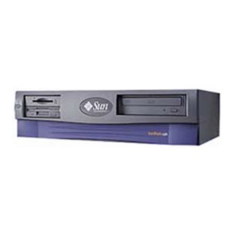
- Page 39 The Sun Blade™ 100 workstations are uniprocessor systems that use the family of UltraSPARC™ processors. They support high-performance CPU module (UltraSPARC-IIe) processing. shows the Sun Blade 100 system. FIGURE 1-1 This chapter contains the following topics: Section 1.1 “Product Overview” on page 1-3 Section 1.2 “I/O Devices”...
- Page 40 Sun Blade 100 System FIGURE 1-1 Sun Blade 100 Service Manual • October 2000...
-
Page 41: Product Description
Product Overview The Sun Blade 100 system provides the following features: Desktop-style system enclosure 200-watt power supply One ATA66 15-Gbyte hard drive, X-option for an additional hard drive CD-ROM drive or DVD-ROM drive CD-quality audio 1.44-megabyte (Mbyte) manual-eject diskette drive... -
Page 42: I/O Devices
I/O Devices The Sun Blade 100 system uses the I/O devices listed in TABLE 1-1 Supported I/O Devices TABLE 1-1 I/O Device Description 17-inch (43-cm) 1280 x 1024 resolution, 76- or 66-Hz refresh rate, 110 dots per inch color monitor... -
Page 43: System Description
4. 3.5-inch drive bay (optional diskette drive shown) 5. 5.25-inch drive bay (optional DVD-ROM drive shown) Note – Although the smart card reader is physically configured in the Sun Blade 100 workstation at introduction, the driver support necessary to make the reader functional is not available in the Solaris release preinstalled on this system. -
Page 44: Figure 1-3 Back Panel Overview
Twisted-pair Ethernet (TPE) connector IEEE 1394 connectors (two) VGA video connector Parallel connector, DB-25 Serial connector (RS-232) SERIAL Audio module headphones connector Audio module line-out connector Audio module line-in connector Audio module microphone connector Sun Blade 100 Service Manual • October 2000... -
Page 45: Replaceable Components
Replaceable Components This section lists the authorized replaceable parts for the Sun Blade 100 system. illustrates the system components. lists the replaceable FIGURE 1-4 TABLE 1-4 components. The numbered components in correlate to the numbered FIGURE 1-4 components listed in... -
Page 46: Figure 1-4 Sun Blade 100 System Replaceable Parts
Sun Blade 100 System Replaceable Parts FIGURE 1-4 Sun Blade 100 Service Manual • October 2000... -
Page 47: Table 1-4 Sun Blade 100 System Replaceable Components
Sun Blade 100 System Replaceable Components TABLE 1-4 Item Component Description CD-ROM drive 48x CD-ROM drive DVD-ROM drive DVD-ROM drive Hard drive (2d drive is X-option) Disk drive, 15-Gbyte, 7200 RPM, ATA Smart card reader Smart card reader with enclosure... - Page 48 1-10 Sun Blade 100 Service Manual • October 2000...
-
Page 49: Sunvts Overview
C H A P T E R SunVTS Overview This chapter contains an overview of the SunVTS™ diagnostic tool. This chapter contains the following topics: Section 2.1 “SunVTS Description” on page 2-1 Section 2.2 “SunVTS Requirements” on page 2-2 Section 2.3 “SunVTS References” on page 2-2 SunVTS Description SunVTS is Sun’s online Validation Test Suite. -
Page 50: Sunvts Requirements
SunVTS 4.x User’s Guide describes how to install, configure, and run the SunVTS diagnostic software. SunVTS 4.x Quick Reference Card provides an overview of how to use the SunVTS CDE interface. SunVTS 4.x Test Reference Manual provides details about each individual SunVTS test. Sun Blade 100 Service Manual • October 2000... -
Page 51: Table 2-1 Sunvts Documentation
These documents are part of the Solaris on Sun Hardware AnswerBook2™ collection. The part number for each document is different for each version of Solaris: check the version of Solaris that you are using and find the appropriate part number for the document. - Page 52 Sun Blade 100 Service Manual • October 2000...
-
Page 53: Power-On Self-Test
C H A P T E R Power-On Self-Test This chapter describes how to initiate power-on self-test (POST) diagnostics. This chapter contains the following topics: Section 3.1 “POST Overview” on page 3-1 Section 3.2 “Pre-POST Preparation” on page 3-1 Section 3.3 “Initializing POST” on page 3-3 Section 3.4 “Maximum and Minimum POST Levels”... -
Page 54: Verifying The Baud Rate
The shell window becomes a TIP window directed to the serial port of the tested system. When power is applied to the tested system, POST messages are displayed in this shell window. 4. When POST is completed, disconnect the TIP connection as follows: Sun Blade 100 Service Manual • October 2000... -
Page 55: Verifying The Baud Rate
a. Open another shell window at the second workstation. b. Type ps -a to view the active TIP line and process ID (PID) number. c. Type the following to disconnect the TIP hardwire process. % kill -9 PID# 3.2.2 Verifying the Baud Rate To verify the baud rate between the tested system and a terminal or another Sun workstation monitor: 1. -
Page 56: Maximum And Minimum Post Levels
CODE EXAMPLE 3-1 POST output with diag-level set to max and a single 512 Mbyte DIMM installed. Note – Video output is disabled while POST is initialized. Sun Blade 100 Service Manual • October 2000... - Page 57 CODE EXAMPLE 3-1 @(#) Sun Blade 100 4.0 [obdiag.fixes] Version 1 created 2000/06/ 09 14:42 Executing Power On SelfTest @(#) Sun (Sun Blade 100) POST 1.2.3 08:55 PM on 05/29/00 Init POST BSS Init System BSS NVRAM Tests NVRAM Battery Detect Test...
- Page 58 PBMA Control/Status Reg Test PBMA Diag Reg Test UltraSPARC-IIe IO Regs Test All Advanced CPU Tests IU ASI Access Test FPU ASI Access Test All CPU Error Reporting Tests CPU Data Access Trap Test Sun Blade 100 Service Manual • October 2000...
-
Page 59: Diag-Level Variable Set To Min
diag-level Variable Set to max CODE EXAMPLE 3-1 CPU Addr Align Trap Test DMMU Access Priv Page Test DMMU Write Protected Page Test Audio Tests Memory Tests Init Memory Info : 512MB at DIMM Slot 0 Start Addr: 0x00000000.00800000 Size: 504 MBytes Init with 0x00000000.00000000: .. - Page 60 CODE EXAMPLE 3-2 @(#) Sun Blade 100 4.0 [obdiag.fixes] Version 1 created 2000/06/09 14:42 Executing Power On SelfTest @(#) Sun Blade 100 POST 1.2.5 09:09 PM on 08/04/00 Init POST BSS Init System BSS NVRAM Tests NVRAM Battery Detect Test...
- Page 61 diag-level Variable Set to min CODE EXAMPLE 3-2 DIMM 2: 0 MBytes = 0x00000000 bytes DIMM 3: 0 MBytes = 0x00000000 bytes Found 1 DIMMs in bank 0 Bank 0: 512 MBytes DIMM0 is a 32M x 8 device MC0 = 0x00000000.56a0bc04 MC1 = 0x00000000.c0804000 MC2 = 0x00000000.0f1f000e MC3 = 0x00000000.00000086...
- Page 62 Info : 512MB at DIMM Slot 0 Start Addr: 0x00000000.00800000 Size: 504 MBytes Status of this POST run:PASS manufacturing mode=SYS_INT Time Stamp [hour:min:sec] 00:52:44 [month/date year] 08/08 2000 Power On Selftest Completed Status = 0000.0000.0000.0000 ffff.ffff.f00b.5ce8 0002.3333.0200.001b 3-10 Sun Blade 100 Service Manual • October 2000...
-
Page 63: Post Progress And Error Reporting
POST Progress and Error Reporting POST progress indications are visible when a TTY-type terminal or a TIP line is connected between the serial port of the tested system and a second Sun workstation. In most cases, POST also attempts to send a failure message to the POST monitoring system. - Page 64 ..........Read ..........................Write 0x55555555.55555555 ..........................Read ..........................Write 0xcccccccc.cccccccc ..........................Read ..........................Write 0xaaaaaaaa.aaaaaaaa ..........................Read ................3-12 Sun Blade 100 Service Manual • October 2000...
- Page 65 Typical Error Code Failure Message CODE EXAMPLE 3-3 ..........Info : 128MB at Dimm Slot 2 Start Addr: 0x00000000.40000000 Size: 128 MBytes Write 0x33333333.33333333 ..........................Read ..*********************** STATUS =FAILED TEST =Block Memory Check SUSPECT=BMX MESSAGE=Memory Blk Checker Pat compare error blk addr 00000000.40400000 ------ Exp ------ ------ Obs ------ 33333333.33333333 00000000.00000000...
- Page 66 Probing /pci@1f,0/pci@5 Device 0 Nothing there Probing /pci@1f,0/pci@5 Device 1 Nothing there Probing /pci@1f,0/pci@5 Device 2 Nothing there Sun Grover (UltraSPARC-IIe 500MHz), No Keyboard OpenBoot 4.0, 384 MB memory installed, Serial #13583889. 3-14 Sun Blade 100 Service Manual • October 2000...
-
Page 67: Bypassing Post
Typical Error Code Failure Message CODE EXAMPLE 3-3 Ethernet address 8:0:20:cf:46:11, Host ID: 61067537. Power On Self Test Failed. Cause: DIMM2 Bypassing POST To bypass POST: At the system prompt, type: ok% setenv diag-level? off ok% setenv diag-switch? false Resetting Variables to Default Settings To set the system NVRAM parameters to the original default settings: At the system prompt, type: ok% set-defaults... - Page 68 POST to execute properly. Removing the optional system components and retesting the system isolates the possibility that those components are the cause of the failure. 3-16 Sun Blade 100 Service Manual • October 2000...
-
Page 69: Troubleshooting Procedures
C H A P T E R Troubleshooting Procedures This chapter describes how to troubleshoot possible hardware problems and suggests corrective actions. This chapter contains the following topics: Section 4.1 “Power-On Failure” on page 4-1 Section 4.2 “Video Output Failure” on page 4-2 Section 4.3 “Hard Drive, CD-ROM, or DVD-ROM Drive Failure”... -
Page 70: Video Output Failure
4. Check that the CPU is properly seated. 5. If video still does not display on the monitor, the monitor, graphics card, or motherboard video chip may be defective. Sun Blade 100 Service Manual • October 2000... -
Page 71: Hard Drive, Cd-Rom, Or Dvd-Rom Drive Failure
Hard Drive, CD-ROM, or DVD-ROM Drive Failure This section provides hard drive, CD-ROM drive, or DVD-ROM drive failure symptoms and suggested actions. Perform the suggested actions until you isolate the problem. Symptoms A hard drive read, write, or parity error is reported by the operating system or a customer application. -
Page 72: Power Supply Test
5. Using a digital voltage meter (DVM), check the power supply output voltages as follows: Note – Power supply connector J501 must remain connected to the riser board. Sun Blade 100 Service Manual • October 2000... -
Page 73: Dimm Failure
a. With the negative probe of the DVM placed on a connector ground (Gnd) pin, position the positive probe on each power pin. See Section B.1 “Power Supply Connectors” on page B-1. b. Verify voltage and signal availability as listed in on page B-2. -
Page 74: Watch-Clock Diagnostic
-- Using Onboard Transceiver - Link Up. passed Using Onboard Transceiver - Link Up. Looking for Ethernet Packets. '.' is a Good Packet. 'X' is a Bad Packet. Type any key to stop........... Sun Blade 100 Service Manual • October 2000... - Page 75 Watch-Net Diagnostic Output Message (Continued) CODE EXAMPLE 4-2 ......................................Watch-Net-All Diagnostic Output Message CODE EXAMPLE 4-3 watch-net-all /pci@1f,0/pci@1,1/network@1,1 Hme register test --- succeeded. Internal loopback test -- succeeded. Transceiver check -- Using Onboard Transceiver - Link Up. passed Using Onboard Transceiver - Link Up.
-
Page 76: Probe-Ide Diagnostic
TABLE 4-3 of each test, and preparation. Note – The diskette drive (floppy) is selected as the test alias name example. Sun Blade 100 Service Manual • October 2000... - Page 77 Test Diagnostic Output Message CODE EXAMPLE 4-5 ok test floppy Testing floppy disk system. A formatted disk should be in the drive. Test succeeded. OpenBoot PROM Selected On-Board Diagnostic Tests TABLE 4-3 Type of Test Description Preparation Tests the system video graphics Diag-switch? NVRAM test screen hardware and the monitor.
-
Page 78: Openboot Diagnostics
Starting the OpenBoot Diagnostics Menu 1. At the ok prompt, type: ok% setenv mfg-mode on mfg-mode = on 2. At the ok prompt, type: ok% setenv diag-switch? true diag-switch? = true 4-10 Sun Blade 100 Service Manual • October 2000... - Page 79 = false ok reset-all Resetting... Software Power ON @(#) Sun Blade 100 UPA/PCI 3.11 Version 2created 2000/03/06 10:31 Clearing E$ Tags Done Clearing I/D TLBs Done Probing Memory Done MEM BASE = 0000.0000.2000.0000 MEM SIZE = 0000.0000.1000.0000...
- Page 80 Probing /pci@1f,0/pci@1/pci@1 at Device 7 Nothing there Probing /pci@1f,0/pci@1/pci@1 at Device 8 Nothing there Probing /pci@1f,0/pci@1/pci@1 at Device 9 Nothing there Probing /pci@1f,0/pci@1/pci@1 at Device a Nothing there Probing /pci@1f,0/pci@1/pci@1 at Device b Nothing there 4-12 Sun Blade 100 Service Manual • October 2000...
- Page 81 Probing /pci@1f,0/pci@1 at Device 2 Nothing there Probing /pci@1f,0/pci@1 at Device 3 Nothing there Probing /pci@1f,0/pci@1 at Device 4 Nothing there Sun Blade 100 UPA/PCI (UltraSPARC-IIe 500 MHz), No Keyboard OpenBoot 3.11, 512 MB memory installed, Serial #9337777. Ethernet address 8:0:20:8e:7b:b1, Host ID: 808e7bb1.
-
Page 82: Openboot Diagnostics
Section 4.7.2.9 “NVRAM Diagnostic” on page 4-20 Section 4.7.2.10 “Audio Diagnostic” on page 4-20 Section 4.7.2.11 “EIDE Diagnostic” on page 4-21 Section 4.7.2.12 “Video Diagnostic” on page 4-22 Section 4.7.2.13 “All Above Diagnostic” on page 4-22 4-14 Sun Blade 100 Service Manual • October 2000... -
Page 83: Pci/Pcio Diagnostic
4.7.2.1 PCI/PCIO Diagnostic To start the PCI/PCIO diagnostic, type at the OBdiag Menu prompt. The PCI/ PCIO diagnostic performs the following tests in sequence: 1. vendor_ID_test verifies the PCIO ASIC vendor ID is 108e. 2. device_ID_test verifies the PCIO ASIC device ID is 1000. 3. -
Page 84: Ebus Dma/Tcr Registers Diagnostic
4. 10_mb_xcvr_loopback_test enables the 10BASE-T data present at the transmit MII data inputs, to be routed back to the receive MII data outputs. 5. 100_mb_phy_loopback_test enables MII transmit data to be routed to the MII receive data path. 4-16 Sun Blade 100 Service Manual • October 2000... -
Page 85: Keyboard Diagnostic
6. 100_mb_twister_loopback_test forces the twisted-pair transceiver into loopback mode. The following code example shows the Ethernet diagnostic output message. Ethernet Diagnostic Output Message CODE EXAMPLE 4-10 Enter (0-13 tests, 14 -Quit, 15 -Menu) ===> 2 TEST=’ethernet_test’ Using Onboard Transceiver - Link Up. SUBTEST=’my_channel_reset’... -
Page 86: Mouse Diagnostic
The following code example shows the diskette drive test output message. Diskette Drive Diagnostic Output Message CODE EXAMPLE 4-13 Enter (0-12 tests, 13 -Quit, 14 -Menu) ===> 5 TEST='floppy_test' SUBTEST='floppy_id0_read_test' Enter (0-12 tests, 13 -Quit, 14 -Menu) ===> 4-18 Sun Blade 100 Service Manual • October 2000... -
Page 87: Parallel Port Diagnostic
4.7.2.7 Parallel Port Diagnostic To start the parallel port diagnostic, type at the OBdiag Menu prompt. The parallel port diagnostic performs the following in sequence: 1. sio-passive-lb sets up the SuperI/O configuration register to enable extended/compatible parallel port select, then does a write 0, walk-one, write 0 x ff to the data register. -
Page 88: Nvram Diagnostic
OBdiag Menu prompt. The audio diagnostic performs the following in sequence: 1. cs4231_test verifies the cs4231 internal registers. 2. Line-in to line-out external loopback test. 3. Microphone to headphone external loopback test. 4-20 Sun Blade 100 Service Manual • October 2000... -
Page 89: Eide Diagnostic
The following code example shows the audio diagnostic output message. Audio Diagnostic Output Message CODE EXAMPLE 4-16 Enter (0-13 tests, 14 -Quit, 15 -Menu) ===> 10 TEST=’audio_test’ SUBTEST=’cs4231_test’ Codec_ID=’8a’ Version_ID=’a0’ SUBTEST=’external_lpbk’ ###OBDIAG_MFG_START### TEST=’audio_test’ STATUS=’FAILED’ SUBTEST=’external_lpbk’ ERRORS=’1 ‘ TTF=’505 ‘ SPEED=’299.80 MHz’ PASSES=’1 ‘... -
Page 90: Video Diagnostic
The following code example shows the all above diagnostic output message. All Above Diagnostic Output Message CODE EXAMPLE 4-19 Enter (0-13 tests, 14 -Quit, 15 -Menu) ===> 13 TEST=’all_pci/cheerio_test’ SUBTEST=’vendor_id_test’ SUBTEST=’device_id_test’ SUBTEST=’mixmode_read’ SUBTEST=’e2_class_test’ SUBTEST=’status_reg_walk1’ SUBTEST=’line_size_walk1’ SUBTEST=’latency_walk1’ SUBTEST=’line_walk1’ SUBTEST=’pin_test’ TEST=’all_dma/ebus_test’ SUBTEST=’dma_reg_test’ SUBTEST=’dma_func_test’ 4-22 Sun Blade 100 Service Manual • October 2000... - Page 91 All Above Diagnostic Output Message (Continued) CODE EXAMPLE 4-19 TEST=’ethernet_test’ Using Onboard Transceiver - Link Up. SUBTEST=’my_channel_reset’ SUBTEST=’hme_reg_test’ SUBTEST=’global_reg1_test’ SUBTEST=’global_reg2_test’ SUBTEST=’bmac_xif_reg_test’ SUBTEST=’bmac_tx_reg_test’ SUBTEST=’mif_reg_test’ SUBTEST=’mac_internal_loopback_test’ SUBTEST=’10mb_xcvr_loopback_test’ SUBTEST=’100mb_phy_loopback_test’ SUBTEST=’100mb_twister_loopback_test’ TEST=’keyboard_test’ SUBTEST=’internal_loopback’ TEST=’mouse_test’ SUBTEST=’mouse_loopback’ ###OBDIAG_MFG_START### TEST=’mouse_test’ STATUS=’FAILED’ SUBTEST=’mouse_loopback’ ERRORS=’1 ‘ TTF=’1011 ‘ SPEED=’299.80 MHz’ PASSES=’1 ‘...
- Page 92 TEST=’audio_test’ SUBTEST=’cs4231_test’ Codec_ID=’8a’ Version_ID=’a0’ SUBTEST=’external_lpbk’ ###OBDIAG_MFG_START### TEST=’audio_test’ STATUS=’FAILED’ SUBTEST=’external_lpbk’ ERRORS=’1 ‘ TTF=’1030 ‘ SPEED=’299.80 MHz’ PASSES=’1 ‘ MESSAGE=’Error: External Audio Test not run: Please set the mfg- mode to sys-ext.’ TEST=’ide_test’ 4-24 Sun Blade 100 Service Manual • October 2000...
-
Page 93: Exiting The Openboot Diagnostic Menu
All Above Diagnostic Output Message (Continued) CODE EXAMPLE 4-19 SUBTEST=’probe-cmd-device’ SUBTEST=’hd-and-cd-check’ TEST=’video_test’ Please connect the monitor and use ttya/ttyb when running this test if you are using the screen it may be become unreadable SUBTEST=’mach64-chip-id-vendor-id-check’ SUBTEST=’video-frame-buffer-test’ SUBTEST=’mach64-walk-one-test’ SUBTEST=’mach64-walk-zero-test’ Enter (0-13 tests, 14 -Quit, 15 -Menu) ===> 4.7.3 Exiting the OpenBoot Diagnostic Menu 1. - Page 94 4-26 Sun Blade 100 Service Manual • October 2000...
-
Page 95: Preparing For Component Removal And Replacement
C H A P T E R Preparing for Component Removal and Replacement This chapter describes the activities you must do to prepare for removal and replacement of internal system components. Note – It is very important that you review the safety requirements, symbols, and precautions in this chapter before you begin to remove or replace system components. -
Page 96: Safety Symbols
Follow all safety precautions. 5.3.1 Modification to Equipment Caution – Do not make mechanical or electrical modifications to the equipment. Sun Microsystems is not responsible for regulatory compliance of a modified Sun product. Sun Blade 100 Service Manual • October 2000... -
Page 97: Placement Of A Sun Product
5.3.2 Placement of a Sun Product Caution – To ensure reliable operation of the Sun product and to protect it from overheating, ensure equipment openings are not blocked or covered. Never place a Sun product near a radiator or hot air register. 5.3.3 Power Cord Connection Caution –... -
Page 98: Lithium Battery
Lithium batteries may explode if mishandled. Do not dispose of a battery in fire. Do not disassemble a battery or attempt to recharge it. Tools Required The following tools are required to service the Sun Blade 100 system. No. 2 Phillips screwdriver (magnetized tip suggested) Needle-nose pliers... -
Page 99: Figure 5-1 Front Panel Power Switch
a. Momentarily press and release the front panel power switch ( ) to FIGURE 5-1 automatically shut down all programs, the operating system, and power off the system. From the system shutdown menu displayed on the monitor, select “Shutdown.” If Solaris is not running in a windowing environment: b. -
Page 100: Removing The System Cover
2. Peel the liner from the copper foil at the opposite end of the wrist strap. 3. Attach the copper end of the wrist strap to the chassis ( FIGURE 5-3 4. Disconnect the AC power cord from the system. Sun Blade 100 Service Manual • October 2000... -
Page 101: Figure 5-3 Attaching The Wrist Strap To The Chassis
Copper end Attaching the Wrist Strap to the Chassis FIGURE 5-3 Chapter 5 Preparing for Component Removal and Replacement... - Page 102 Sun Blade 100 Service Manual • October 2000...
-
Page 103: Removing And Replacing Major Subassemblies
C H A P T E R Removing and Replacing Major Subassemblies This chapter describes how to remove and replace the major subassemblies. This chapter contains the following topics: Section 6.1 “Power Supply” on page 6-1 Section 6.2 “Cable Assemblies” on page 6-3 Section 6.3 “Speaker Assembly”... -
Page 104: Replacing The Power Supply
4. Connect the power cable connector to the riser board connector J501. 5. Detach the wrist strap, replace the system cover, and power on the system as described in Chapter 9 “Finishing Component Replacement.” Sun Blade 100 Service Manual • October 2000... -
Page 105: Cable Assemblies
Cable Assemblies The following cable assemblies can be removed and replaced: Diskette drive cable assembly Diskette drive power cable assembly Primary IDE cable assembly Secondary IDE cable assembly Smart card reader cable assembly Power switch/LED assembly Note – All system cable assemblies are part of a cable kit; they cannot be ordered separately. -
Page 106: Replacing The Diskette Drive Data Cable Assembly
4. If you moved the fan assembly, replace it. See Section 6.4.2 “Replacing the Fan Assembly” on page 6-17. 5. Detach the wrist strap, replace the system cover, and power on the system as described in Chapter 9 “Finishing Component Replacement.” Sun Blade 100 Service Manual • October 2000... -
Page 107: Removing The Diskette Drive Power Cable Assembly
6.2.3 Removing the Diskette Drive Power Cable Assembly 1. Power off the system, remove the system cover, and attach an antistatic wrist strap as described in Chapter 5 “Preparing for Component Removal and Replacement.” Caution – Use proper ESD grounding techniques when handling components. Wear an antistatic wrist strap and use an ESD-protected mat. -
Page 108: Replacing The Diskette Drive Power Cable Assembly
2. Disconnect the primary IDE cable assembly connectors from the following FIGURE 6-4 CD-ROM or DVD-ROM drive Primary hard drive Riser board (J504: also labeled IDE1) 3. Remove the primary IDE cable assembly from the chassis. Sun Blade 100 Service Manual • October 2000... -
Page 109: Replacing The Primary Ide Cable Assembly
CD-DVD-ROM IDE 1 (J504) Removing and Replacing the Primary IDE Cable Assembly FIGURE 6-4 6.2.6 Replacing the Primary IDE Cable Assembly 1. Position the primary IDE cable assembly into the chassis ( FIGURE 6-4 2. Connect the primary IDE cable assembly connectors to the following: Primary hard drive CD-ROM or DVD-ROM drive Riser board (J504: also labeled IDE1) -
Page 110: Replacing The Secondary Ide Cable Assembly
1. Position the secondary IDE cable assembly into the chassis ( FIGURE 6-5 2. Connect the secondary IDE cable assembly connectors to the following: Secondary hard drive Riser board (J503: also labeled IDE2) Sun Blade 100 Service Manual • October 2000... -
Page 111: Removing The Smart Card Reader Cable Assembly
Note – Ensure that the cable assembly connectors are properly oriented by aligning the connector keys. 3. Detach the wrist strap, replace the system cover, and power on the system as described in Chapter 9 “Finishing Component Replacement.” 6.2.9 Removing the Smart Card Reader Cable Assembly 1. -
Page 112: Replacing The Smart Card Reader Cable Assembly
2. If you moved the fan assembly, replace it. See Section 6.4.2 “Replacing the Fan Assembly” on page 6-17. 3. Detach the wrist strap, replace the system cover, and power on the system as described in Chapter 9 “Finishing Component Replacement.” 6-10 Sun Blade 100 Service Manual • October 2000... -
Page 113: Removing The Power Switch/Led Assembly
6.2.11 Removing the Power Switch/LED Assembly 1. Power off the system, remove the system cover, and attach an antistatic wrist strap as described in Chapter 5 “Preparing for Component Removal and Replacement.” Caution – Use proper ESD grounding techniques when handling components. Wear an antistatic wrist strap and use an ESD-protected mat. -
Page 114: Replacing The Power Switch/Led Assembly
8. Press the LED out of the chassis from the front panel side. 9. Remove the power switch/LED assembly from the chassis. 6.2.12 Replacing the Power Switch/LED Assembly 1. Position the power switch/LED assembly into the chassis ( FIGURE 6-8 6-12 Sun Blade 100 Service Manual • October 2000... -
Page 115: Speaker Assembly
2. Attach the power switch to the chassis with the washer and nut. 3. Press the LED into the chassis from the rear of the front panel. 4. Route the cable along the chassis. 5. Close the cable routing clips. 6. - Page 116 5. Disconnect the speaker cable from connector J12 on the riser board. 6. Press the speaker retaining tab on the chassis front panel. 7. Remove the speaker assembly from the chassis. 6-14 Sun Blade 100 Service Manual • October 2000...
-
Page 117: Replacing The Speaker Assembly
J12 connector Removing and Replacing the Speaker Assembly FIGURE 6-9 6.3.2 Replacing the Speaker Assembly 1. Position the speaker assembly into the chassis ( FIGURE 6-9 2. Grasp the speaker and press the speaker into the three chassis speaker slots. 3. -
Page 118: Fan Assembly
3. Disconnect the fan assembly power cable connector from riser board connector J4 FIGURE 6-10 4. Open the cable retaining clip and remove the fan cable. 5. Press the fan assembly retaining tabs and remove the fan assembly from the chassis. 6-16 Sun Blade 100 Service Manual • October 2000... -
Page 119: Replacing The Fan Assembly
J4 connector Removing and Replacing the Fan Assembly FIGURE 6-10 6.4.2 Replacing the Fan Assembly 1. Position the fan assembly, ensuring that the fan retaining tabs are aligned with the chassis retaining slots ( FIGURE 6-10 2. Press the fan assembly into the chassis slots. 3. - Page 120 6-18 Sun Blade 100 Service Manual • October 2000...
-
Page 121: Removing And Replacing Storage Devices
C H A P T E R Removing and Replacing Storage Devices This chapter describes how to remove and replace the Sun Blade 100 storage devices. This chapter contains the following topics: Section 7.1 “Diskette Drive” on page 7-1 Section 7.2 “Smart Card Reader” on page 7-3 Section 7.3 “Hard Drives”... -
Page 122: Replacing The Diskette Drive
7. Using a No. 2 Phillips screwdriver, remove the three screws securing the diskette drive to the peripheral assembly. 8. Remove the diskette drive from the peripheral assembly. 7.1.2 Replacing the Diskette Drive 1. Position the diskette drive into the peripheral assembly ( FIGURE 7-1 Sun Blade 100 Service Manual • October 2000... -
Page 123: Smart Card Reader
2. Using a No. 2 Phillips screwdriver, replace the three screws securing the diskette drive to the peripheral assembly. 3. Position the peripheral assembly into the chassis, aligning the three holes on the assembly with the three screws on the chassis. 4. -
Page 124: Replacing The Smart Card Reader
Removing and Replacing the Smart Card Reader FIGURE 7-2 8. Remove the smart card reader from the peripheral assembly. 7.2.2 Replacing the Smart Card Reader 1. Slide the smart card reader into the peripheral assembly. Sun Blade 100 Service Manual • October 2000... -
Page 125: Hard Drives
2. Using a No. 2 Phillips screwdriver, replace the three screws securing the smart card reader to the peripheral assembly ( FIGURE 7-2 3. Position the peripheral assembly into the chassis, aligning the three holes on the assembly with the three screws on the chassis ( FIGURE 7-1 4. - Page 126 7. Using a No. 2 Phillips screwdriver, remove the four screws securing the hard drive to the hard drive tray. 8. Lift the hard drive tray from the hard drive. CD/DVD-ROM drive IDE cable connector IDE 1 Removing and Replacing a Primary Hard Drive FIGURE 7-3 Sun Blade 100 Service Manual • October 2000...
-
Page 127: Replacing A Primary Hard Drive
7.3.2 Replacing a Primary Hard Drive Note – Read the hard drive product guide for information about jumpers, switch settings, or other installation tasks. Note – Before you replace any hard drive, verify that the hard drive mode-select jumper is set to “CS,” “Enable Cable Select,” or “Cable Select.” 1. - Page 128 8. Using a No. 2 Phillips screwdriver, install the four screws that secure the drive to the hard drive tray. 9. While ensuring that the cables are not damaged, slide the hard drive tray into the chassis until the spring-loaded latch clicks into place. Sun Blade 100 Service Manual • October 2000...
-
Page 129: Figure 7-4 Installing A Secondary Hard Drive
CD/DVD-ROM drive IDE cable connector IDE 1 Secondary hard drive Installing a Secondary Hard Drive FIGURE 7-4 10. Verify that the secondary IDE cable connector is connected to riser board connector IDE2 (J503). See FIGURE 7-5. Note – Ensure that the cables are properly oriented by aligning the connector keys. 11. -
Page 130: Cd-Rom Or Dvd-Rom Drive
1. Remove any CD or DVD from the drive. 2. Power off the system, remove the system cover, and attach an antistatic wrist strap as described in Chapter 5 “Preparing for Component Removal and Replacement.” 7-10 Sun Blade 100 Service Manual • October 2000... -
Page 131: Replacing A Cd-Rom Or Dvd-Rom Drive
Caution – Use proper ESD grounding techniques when handling components. Wear an antistatic wrist strap and use an ESD-protected mat. Store ESD-sensitive components in antistatic bags before placing them on any surface. 3. Remove the following from the back of the CD-ROM or DVD-ROM drive FIGURE 7-6 CD-ROM or DVD-ROM drive IDE cable connector Power cable connector... - Page 132 4. Using a No. 2 Phillips screwdriver, replace the two screws securing the CD-ROM or DVD-ROM drive to the chassis. 5. Detach the wrist strap, replace the system cover, and power on the system as described in Chapter 9 “Finishing Component Replacement.” 7-12 Sun Blade 100 Service Manual • October 2000...
-
Page 133: Removing And Replacing The Motherboard And Related Components
C H A P T E R Removing and Replacing the Motherboard and Related Components This chapter describes how to remove and replace the Sun Blade 100 motherboard and motherboard components. This chapter contains the following topics: Section 8.1 “CPU” on page 8-2 Section 8.2 “NVRAM/TOD”... -
Page 134: Cpu
6. Gently lift the heatsink and CPU from the socket: if the CPU does not lift-off easily, ensure that the locking lever is fully released. 7. Place the CPU on an antistatic mat with the heatsink facing up. Sun Blade 100 Service Manual • October 2000... -
Page 135: Replacing The Cpu
Heatsink retaining clip Heatsink Heatsink key CPU Key CPU socket CPU locking lever Removing and Replacing the CPU FIGURE 8-1 8.1.2 Replacing the CPU Note – If you are replacing an old CPU, the CPU will be permanently bonded to the heatsink. - Page 136 Note – For diagnostics, you can always choose CPU Mode A. This mode will work with all CPU speeds and types. However, Mode A may be a lower speed than the CPU. Sun Blade 100 Service Manual • October 2000...
-
Page 137: Figure 8-2 Example Of Open And Closed Speed Setting Jumpers
Note – A jumper switch is closed (sometimes referred to as shorted) with the plastic cap inserted over two pins of the jumper. A jumper is open with the plastic cap inserted over one or no pin(s) of the jumper. Motherboard jumpers are identified as JP. -
Page 138: Nvram/Tod
Caution – Do not remove the NVRAM/TOD from the carrier. 4. Grasp the NVRAM/TOD carrier at each end and pull it straight up, gently wiggling it as necessary. 5. Place the NVRAM/TOD and carrier on an antistatic mat. Sun Blade 100 Service Manual • October 2000... -
Page 139: Replacing The Nvram/Tod
NVRAM/TOD Carrier Socket keys Removing and Replacing the NVRAM/TOD FIGURE 8-3 8.2.2 Replacing the NVRAM/TOD 1. Replace the NVRAM/TOD as follows ( FIGURE 8-3 a. Position the NVRAM/TOD carrier on the motherboard. on page C-23. FIGURE C-7 b. Carefully insert the NVRAM/TOD carrier into the motherboard socket. Note –... -
Page 140: Dimms
Note – Always remove and replace DIMMs in order, beginning with the DIMM closest to the edge of the motherboard ( FIGURE 8-4 Sun Blade 100 Service Manual • October 2000... -
Page 141: Figure 8-4 Dimm Installation Order
DIMM Installation Order FIGURE 8-4 2. Locate the DIMM to be removed. 3. Push the ejection levers at each end of the DIMM connector away from the DIMM FIGURE 8-5 4. Lift the DIMM straight up from the motherboard connector. 5. -
Page 142: Replacing A Dimm
2. Position the DIMM in the connector, ensuring that the notches on the bottom of the DIMM are aligned with the connector alignment keys ( FIGURE 8-5 Note – DIMM alignment notches and connectors are keyed to ensure proper DIMM orientation. 8-10 Sun Blade 100 Service Manual • October 2000... - Page 143 Caution – If the DIMM is not seated into its slot evenly, it can cause electrical short circuits that will damage the system. Ensure that all contacts engage at the same time by pressing evenly on both ends of the DIMM—do not rock the DIMM into place.
-
Page 144: Pci Card
6. Grasp the two corners of the PCI card and pull the card straight out from the riser board connector. 7. Place the PCI card on an antistatic mat. 8-12 Sun Blade 100 Service Manual • October 2000... -
Page 145: Replacing A Pci Card
PCI card bracket retainer Detent Retractable card guide Removing and Replacing a PCI Card FIGURE 8-6 8.4.2 Replacing a PCI Card Note – Read the PCI card product guide for information about jumper or switch settings, slot requirements, and required tools. 1. - Page 146 9. Connect all external cables to the PCI card. 10. Detach the wrist strap, replace the system cover, and power on the system as described in Chapter 9 “Finishing Component Replacement.” 8-14 Sun Blade 100 Service Manual • October 2000...
-
Page 147: Motherboard
Motherboard To remove and replace a motherboard, proceed as follows. Caution – Use an antistatic mat when working with the motherboard. An antistatic mat contains the cushioning needed to protect the underside components, to prevent motherboard flexing, and to provide antistatic protection. 8.5.1 Removing the Motherboard 1. - Page 148 If the same ID and Ethernet address will be used on the replacement motherboard, remove the NVRAM/TOD carrier from the motherboard and install it on the new motherboard. See Section 8.2.2 “Replacing the NVRAM/TOD” on page 8-7. 8-16 Sun Blade 100 Service Manual • October 2000...
-
Page 149: Replacing The Motherboard
Removing and Replacing the Motherboard FIGURE 8-7 8.5.2 Replacing the Motherboard Replace the motherboard as follows ( FIGURE 8-7 Caution – Handle the motherboard by the back panel or the edges only. Note – If you will re-install the same motherboard you do not need to change the CPU speed setting jumpers or the Flash PROM jumpers. -
Page 150: Figure 8-8 Jp1/Jp2 Jumper Settings For The Flash Prom
Push the motherboard ejection lever toward the chassis to lock the motherboard into the riser board connector. b. Verify that the motherboard is firmly locked into the riser board by gently pressing the motherboard tray into the riser board connector. 8-18 Sun Blade 100 Service Manual • October 2000... - Page 151 7. Replace the PCI card(s). See Section 8.4.2 “Replacing a PCI Card” on page 8-13. 8. Detach the wrist strap, replace the system cover, and power on the system as described in Chapter 9 “Finishing Component Replacement.” Chapter 8 Removing and Replacing the Motherboard and Related Components 8-19...
-
Page 152: Riser Board
See Section 8.5.1 “Removing the Motherboard” on page 8-15. 5. Using a No. 2 Phillips screwdriver, remove the three screws securing the riser board to the system chassis ( FIGURE 8-9 6. Remove the riser board from the chassis. 8-20 Sun Blade 100 Service Manual • October 2000... -
Page 153: Replacing The Riser Board
Screws (3) Removing and Replacing the Riser Board FIGURE 8-9 8.6.2 Replacing the Riser Board 1. Position the riser board into the chassis ( FIGURE 8-9 The riser board fits between the staggered tabs on the chassis. 2. Using a No. 2 Phillips screwdriver, replace the three screws securing the riser board to the system chassis. - Page 154 8-22 Sun Blade 100 Service Manual • October 2000...
-
Page 155: Finishing Component Replacement
C H A P T E R Finishing Component Replacement This chapter describes the activities you must complete after you finish removing and replacing internal system components. This chapter also explains how to externally control standby operation. This chapter contains the following topics: Section 9.1 “Replacing the System Cover”... -
Page 156: Powering On The System
2. Reconnect and turn on power to any peripherals (so that the system can recognize the peripherals when it is powered on). 3. Press the front panel power switch ( FIGURE 9-2 Power switch System Power Switch FIGURE 9-2 4. Verify the following: Sun Blade 100 Service Manual • October 2000... - Page 157 a. The front panel power indicator LED is on. b. The system fans are spinning. 5. If the system does not power on, see the Troubleshooting section in the Getting Started Guide. Chapter 9 Finishing Component Replacement...
- Page 158 Sun Blade 100 Service Manual • October 2000...
-
Page 159: Openboot Emergency Procedures
C H A P T E R OpenBoot Emergency Procedures The introduction of USB keyboards with Sun’s newest desktop systems has made it necessary to change some of the OpenBoot emergency procedures, specifically, the Stop-N, Stop-D, and Stop-F commands that are available on systems that have standard (non-USB) keyboards and are not supported on systems that have USB keyboards. -
Page 160: Openboot Emergency Procedures For Systems With Usb Keyboards
’diag-switch?’ is true ’use-nvramrc?’ is false ’input-device’, ’output-device’ are defaulted ’ttya-mode’, ’ttyb-mode’ are defaulted These changes are temporary and the original values will be restored after the next hardware or software reset. 10-6 Sun Blade 100 Service Manual • October 2000... -
Page 161: Stop-F Functionality
Some NVRAM configuration parameters are reset to their defaults. They include parameters that are more likely to cause problems, such as TTYA settings. These NVRAM settings are only reset to their defaults for this power cycle. If you do nothing other than resetting the system at this point, the values are not permanently changed. - Page 162 10-8 Sun Blade 100 Service Manual • October 2000...
-
Page 163: Product Specifications And Reference Information
A P P E N D I X Product Specifications and Reference Information This appendix provides product specifications for the Sun Blade 100 system. Section A.1 “Physical Specifications” on page A-1 Section A.2 “Electrical Specifications” on page A-2 Section A.5 “Modem Setup Specifications” on page A-5 Section A.3 “Environmental Requirements”... -
Page 164: Electrical Specifications
Electrical Specifications The following table lists the electrical specifications for the Sun Blade 100 system. Sun Blade 100 System Electrical Specifications TABLE A-2 Parameter Value AC input 47 to 63 Hz, 90 to 132 VAC or 180 to 264 VAC... -
Page 165: Reference Information
A.4.2 Jumper Settings Before you install a CD-ROM or DVD-ROM drive or a hard drive in a Sun Blade 100 system, verify that the drive’s back panel mode-select jumper is set as follows: Set the CD-ROM drive jumper (located on the CD-ROM drive back panel) to either “CS,”... -
Page 166: Cd Handling And Use
A.4.3 CD Handling and Use The following topics are discussed in this section. “Inserting a CD Into the CD-ROM or DVD-ROM Drive” on page A-4 “Ejecting a CD From the CD-ROM or DVD-ROM Drive” on page A-4 “Cleaning the CD-ROM or DVD-ROM Drive” on page A-4 “Handling and Storing CDs”... -
Page 167: Modem Setup Specifications
A.4.3.4 Handling and Storing CDs Follow these guidelines when handling and storing CDs: Handle CDs only by their edges; avoid touching CD surfaces. Do not write on CDs with permanent marking pens. Do not use CDs in high-dust environments. Keep CDs out of direct sunlight, away from extreme sources of heat or cold, and away from dust and moisture. -
Page 168: Changing The Serial Port Speed
5. From the Use Template menu, choose one of the following: Modem - Dial-out only Modem - Dial-in only Modem - Bidirectional 6. Choose Apply. 7. Set your modem auto-answer switch to one of the following: Off – Dial-out only On –... -
Page 169: Modem Switch Settings (At Commands
A.5.3.2 Modem Switch Settings (AT Commands) Note – These settings are guidelines only. These guidelines might change depending on site requirements and the chosen modem. Enable transmit flow control (AT&H1) [suggested setting] (Required for sending binary/8-bit data.) Set link rate to fixed (Will not track modem data rate, AT&Bn;... - Page 170 Sun Grover Service Manual • October 2000...
-
Page 171: Signal Descriptions
Section B.7 “Audio Connectors” on page B-10 Section B.8 “Video Connector” on page B-11 Power Supply Connectors There is one power supply connector on the riser board. The Sun Blade 100 riser board uses a standard ATX style connector (J501). Power Supply Connector J501 Pin Configuration... -
Page 172: Table B-1 Power Supply Connector J501 Pin Assignments
Power Supply Connector J501 Pin Assignments TABLE B-1 Signal Description +3.3V +3.3 VDC +3.3V +3.3 VDC Chassis ground +5 VDC Chassis ground +5 VDC Chassis ground PWR_OK Power okay 5VSB +12V +12 VDC +3.3V +3.3 VDC -12V -12 VDC Chassis ground PS_ON Power supply on Chassis ground... -
Page 173: Universal Serial Bus Connector
Universal Serial Bus Connector Four universal serial bus (USB) connectors are located on the back panel. Two are used for the Sun USB Type-6 keyboard and the USB mouse. USB Connector J17, J18 Pin Configuration FIGURE B-2 USB Connector J17, J18 Pin Assignments TABLE B-2 Signal Name USB0_VCC... -
Page 174: Ieee 1394 Connector
IEEE 1394 Connector Two IEEE 1394 connectors are located on the back panel. IEEE 1394 Connector J20, J30 Pin Configuration FIGURE B-3 IEEE 1394 Connector J20, J30 Pin Assignments TABLE B-3 Signal Name Description P1394_EX_BUSPOWER Bus power Ground CM_P1394_TPB1_OUT_N CM_P1394_TPB1_OUT_P CM_P1394_TPA1_OUT_N CM_P1394_TPA1_OUT_P Sun Grover Service Manual •... -
Page 175: Twisted-Pair Ethernet Connector
Twisted-Pair Ethernet Connector The twisted-pair Ethernet (TPE) connector is an RJ-45 type connector located on the back panel. Caution – Connect only TPE-type cables into the TPE connector. TPE Connector J19 Pin Configuration FIGURE B-4 TPE Connector J19 Pin Assignments TABLE B-4 Signal Description... -
Page 176: Tpe Cable-Type Connectivity
B.4.1 TPE Cable-Type Connectivity The following types of TPE cables can be connected to the TPE connector: For 10BASE-T applications, unshielded twisted-pair (UTP) cable: Category 3 (UTP-3, “voice grade”) Category 4 (UTP-4) Category 5 (UTP-5, “data grade”) For 100BASE-T applications, UTP cable, UTP-5, “data grade” B.4.2 External UTP-5 Cable Lengths TPE UTP-5 Cables... -
Page 177: Serial Port Connector
Serial Port Connector The serial port connector is a DB-9 type connector located on the back panel. The serial port connector provides asynchronous serial communications. Serial Port Connector J36 Pin Configuration FIGURE B-5 Serial Port Connector J36 Pin Assignments TABLE B-6 Signal Description Carrier detect... -
Page 178: Parallel Port Connector
Parallel Port Connector The parallel port connector is a DB-25 type connector located on the back panel. Parallel Port Connector J9 Pin Configuration FIGURE B-6 Parallel Port Connector J9 Pin Assignments TABLE B-7 Signal Description Data_Strobe_L Set low during forward channel transfers to latch data into peripheral device. - Page 179 Parallel Port Connector J9 Pin Assignments (Continued) TABLE B-7 Signal Description INIT_L Driven low by the host to reset peripheral. PAR_IN_L Set low by the host to select peripheral device for forward channel transfer. Set high to indicate bus direction is from peripheral to host.
-
Page 180: Audio Connectors
Audio Connectors The audio connectors are located on the back panel. These connectors use EIA standard 0.125-inch (3.5-mm) jacks. Headphones Line-out Line-in Microphone Audio Connector Configuration FIGURE B-7 Audio Connector Line Assignment TABLE B-8 Component Headphones Line-Out Line-In Microphone Left channel Left channel Left channel Left channel... -
Page 181: Video Connector
Video Connector The video connector is a 15-pin mini D-sub connector located on the back panel. Video Connector J37 Pin Configuration FIGURE B-8 Video Connector J37 Pin Assignments TABLE B-9 Signal Description Red video signal Green Green video signal Blue Blue video signal Ground Not connected... - Page 182 B-12 Sun Grover Service Manual • October 2000...
-
Page 183: System
A P P E N D I X Functional Description This appendix provides a functional description of the Sun Blade 100 system. Section C.1 “System” on page C-1 Section C.2 “Motherboard Components” on page C-3 Section C.3 “Reset Types” on page C-9 Section C.4 “Clocking”... -
Page 184: Cpu
PROM OpenBoot SGRAM PROM 8 Mbytes Serial Parallel SVGA Line out 1394 (2) Ethernet USB (4) Line in port port 10/100 Headphone RJ-45 Sun Blade 100 System Functional Block Diagram FIGURE C-1 Sun Blade 100 Service Manual • October 2000... - Page 185 Motherboard Components This section describes all the Sun Blade 100 system components. Most of the devices are connected through the PCI interface that is supported by the CPU. The CPU has one 32-bit 33/66 MHz PCI bus. The PCI bus from the CPU is 3.3V. All the PCI devices on the motherboard are 3.3V devices.
-
Page 186: Ichip2 Asic
C.2.3 SouthBridge ASIC The Sun Blade 100 system uses the SouthBridge ASIC which is a highly integrated system I/O chip set in a 328-pin, ball grid array (BGA) package. It has the following integrations:... -
Page 187: Pci Ide Controller
C.2.3.2 PCI IDE Controller There are two IDE channels within the IDE controller to support up to four devices. Each channel can operate at DMA mode 4 speed independently. The target devices are one or two UltraDMA/66 capable hard drives and a DVD-ROM or CD-ROM drive. -
Page 188: Smbus Interface
SMBus Interface The SMBus host controller provides the communication channel with other serial devices through SMBus protocol. In the Sun Blade 100 system, this SMBus is connected to the four SDRAM DIMM modules, so that on system power-up OpenBoot PROM can access the information regarding each DIMM type and configuration stored inside the serial EEPROM on each DIMM module. -
Page 189: Usb
OpenHCI Host Controller 1.5 and 12 Mb/s transfer rate Four host ports The Sun Blade 100 uses two USB ports for the keyboard and mouse. See Appendix D for details. C.2.5.3 IEEE 1394 The Sun Blade 100 provides a dual IEEE-1394 interface for faster asynchronous peripheral devices of transfer rate up to 400Mb/s. -
Page 190: Smart Card Interface
Smart Card Interface Note – Although the smart card reader is physically configured in the Sun Blade 100 workstation at introduction, the driver support necessary to make the reader functional is not available in this Solaris release. The smart card reader driver support will be made available in a future Solaris release. -
Page 191: Nvram/Tod
+12V I2C_CLK_L I2C_DATA_L SC_INT_L Smart Card Interface Header FIGURE C-4 C.2.9 NVRAM/TOD The system requires at least 8 Kbytes of non-volatile static RAM to store the variables for the operating system and a real time clock to do timekeeping. This device has both functions integrated plus the self-contained battery. -
Page 192: Clocking
Clocking C.4.1 Clock Generation There are four clock domains in Sun Blade 100. The domains are CPU, SDRAM, PCI, and miscellaneous clocks. All the clocks in those four domains are generated from clock synthesizers or dedicated crystals on the motherboard except SDRAM clocks, which are generated by the CPU. -
Page 193: Openboot Prom Jumpers: Cpu Speed Selection
1-2, 5-6 closed 3-4, 5-6 closed 1-2, 3-4, 5-6 closed Spare OpenBoot PROM configuration TABLE C-3 EGPIO[12:11] Power Control C.5.1 Power Switch The Sun Blade 100 system power on/off button is on the front panel. Appendix C Functional Description C-11... -
Page 194: Power-On
Power-On There are two conditions that will turn the system power on through the power on/ off control circuitry on the Sun Blade 100 motherboard. The system was originally turned off and the front panel power on/off button is pushed. -
Page 195: Power-On Beep
Tolerance needs to keep at +3% ~ -3% with dynamic current load of 1A to 12.5A 85% efficiency at typical load (7A), 82% at light load (1.3A) The voltage sensor should be routed to the farthest CPU power pin input. Note –... -
Page 196: Power-On Led Control
LED or to have LED blink at the rate of 1Hz or 2Hz. C.5.3 Optional Secondary Hard Drive The Sun Blade 100 has a provision for a second hard drive on the hard drive tray. shows the configuration. FIGURE C-5... - Page 197 WE[0,1] SCLK_OUT IO_SCLK ECC[0:7] MD[],ECC[], MD[0:63] WE[2,3] CKE2 CKE3 CKE[2,3] CS[4,5] CS[6,7] CS[4:7] CAS2 CAS3 CAS[2,3] RAS2 RAS3 RAS[2,3] CLK[4,5] CLK[6,7] CLK[4:7] MAB[0:12],BB[0:1] DIMM2 DIMM3 MAB[0:12],BB[0:1] MAB[0:12],BB[0:1] Sun Blade 100 Memory Block Diagram FIGURE C-6 Appendix C Functional Description C-15...
-
Page 198: Sdram Address Multiplexing
A22 A23 A24 A23 A24 A25 A24 A25 A26 A25 A26 MA12 MA11 MA10 A10 A10 A10 A10 A10 A10 A10 A10 A10 A10 A7 A7 A6 A6 A5 A5 A4 A4 C-16 Sun Blade 100 Service Manual • October 2000... -
Page 199: Dimms
C.6.2.1 Speed and Timing The Sun Blade 100 uses PC100 compliant SDRAM DIMMs. The motherboard can support up to 2 Gbytes with four DIMM slots. The CPU can address 2 Gbytes of memory. The current maximum main memory is 512 Mbyte per slot. The DIMMs... -
Page 200: Address Mapping
0x000.0000.0000 - 1 Gbyte Main memory Cacheable 0x000.3FFF.FFFF 0x000.4000.0000 - Do not use Undefined Cacheable 0x1FF.FFFF.FFFF 0x1FC.0000.0000 - 8 Gbytes UPA graphics Non-cacheable 0x1FD.FFFF.FFFF 0x1FE.0000.0000 - 8 Gbytes CPU IO Non-cacheable 0x1FF.FFFF.FFFF C-18 Sun Blade 100 Service Manual • October 2000... -
Page 201: Pci Address Assignments
C.7.2 PCI Address Assignments The following table lists the PCI address assignments. PCI Address Assignments TABLE C-9 Address Range in PCI Address Size PCI Space Addressed Notes 0x8000.0000 - 0xBFFF.FFFF 1 Gbyte Primary PCI DVMA space CPU DVMA register (equals 0x30) 0x4000.0000 - 0x7FFF.FFFF 1 Gbyte PCI bus A memory space... -
Page 202: Interrupts
The Sun Blade 100 is Energy Star compliant. The Sun Blade 100 uses the Tier2, Guideline B of EPA’s 3.0 MOU. This means that when Sun Blade 100 is in a Power Managed state the maximum power consumption will be 24 Watts or less. -
Page 203: Energy Star
C.9.1 Energy Star The Sun Blade 100 motherboard will follow the guidelines set up by the U.S. EPA’s Energy Star program. The current MOU is revision 3.0. Refer to: http://www.epa.gov/appdstar/esoe/moureq.html The current Energy Star requirement for computers with power supplies that are from 0 to 200W is 30W when in power-saving mode. -
Page 204: Energy Star Tier 2, Guideline B
Note – Activity on the USB keyboard or mouse indicates user intervention, causing USB framework power to remove the system from low power mode. C.10 Motherboard The following figure illustrates a layout diagram of the system motherboard. C-22 Sun Blade 100 Service Manual • October 2000... - Page 205 NVRAM/TOD Battery U5 U4 U3 U2 DIMMs JTAG J20 J30 Audio Motherboard Layout Diagram FIGURE C-7 Appendix C Functional Description C-23...
-
Page 206: Riser Board
TABLE C-13 Connector Description PCI connector Power/LED connector PCI connector Fan connector PCI connector Debug connector Debug connector Smart card connector Diskette drive data connector Diskette drive power connector Speaker connector C-24 Sun Blade 100 Service Manual • October 2000... -
Page 207: Jumper Descriptions
Power J501 J502 J504 IDE 1 J503 IDE 2 Riser Board Layout Diagram, Side 2 FIGURE C-9 Riser Board Connectors, Side 2 TABLE C-14 Connector Description J501 Power supply connector J502 IDE drive power connector J503 Secondary IDE channel connector J504 Primary IDE channel connector C.12... -
Page 208: Enclosure
One 1.6-inch (4.064-cm) CD-ROM drive or DVD-ROM drive One hard drive bay holding the primary hard drive and an optional secondary hard drive (both drives are 3.5-inch (8.89-cm) Four DIMMs Three PCI slots Removable motherboard Riser board C-26 Sun Blade 100 Service Manual • October 2000... -
Page 209: Usb Supplement
A P P E N D I X USB Supplement This appendix contains information on the following topics: Section D.1 “USB Keyboard and Mouse” on page D-27. Section D.2 “USB Power Management” on page D-28. USB Keyboard and Mouse The following USB keyboard and mouse information is provided for your Type-6 USB keyboard and USB mouse: The Sleep key on the USB keyboard behaves differently than the power key on Type-5 or Type-6 keyboards. -
Page 210: Usb Power Management
(/dev/[r]dsk/cXtYdZsN) On hot remove mass storage drives, /dev/[r]dsk links remain persistent. Type devfsadm -C to remove stale links. System Checkpoint/Resume will fail if a file system is mounted. D-28 Sun Blade 100 Service Manual • October 2000... -
Page 211: Printer Devices
D.2.2 Printer Devices After plugging in the printer, type lpadmin or printmgr to configure printer To find out which of /dev/printers/N is a USB printer, type ls -l on /dev/printers and find out which symbolic links point to the usbprn device. For Lexmark printers choose HP as the printer type in printmgr D.2.3... -
Page 212: Man Pages Available
D.2.6 Man Pages Available ohci(7D), uhci(7D), hubd(7D), usb_mid(7D), hid(7D), scsa2usb(7D), usbprn(7D), usbkb(7M), usbms(7M) D-30 Sun Blade 100 Service Manual • October 2000... - Page 213 Glossary address A unique location within computer or peripheral memory. Reference made to an address is usually for retrieving or storing data. Advanced PCI bridge. A PCI-to-PCI bridge ASIC that features a connection path between a 32-bit bus operating at speeds up to 66 MHz on the primary interface and two 32-bit, 5 VDC or 3.3 VDC, PCI buses (each operating at 33 MHz), on the secondary interface.
- Page 214 FIFO First-in-first-out. flash PROM Flash programmable read-only memory. Gbyte Gigabyte. Graphical user interface. Insulation displacement connector. Integrated drive electronics. Input/output. JTAG IEEE standard 1149.1. Kbyte Kilobyte. Local area network. Light-emitting diode. Glossary-2 Sun Blade 100 Service Manual • October 2000...
- Page 215 Media access controller. Mbyte Megabyte. MBps Megabytes per second. Mbps Megabits per second. Memory controller unit. Megahertz. Media independent interface. MQFP Metric quad flat package Nanosecond. NVRAM Non-volatile random access memory. Stores system variables used by the boot PROM. Contains the system hostID number and Ethernet address. OpenBoot PROM A routine that tests the network controller, diskette drive system, memory, cache, system clock, network monitoring, and control registers.
- Page 216 Time of day. A timekeeping integrated circuit. TQFP Thin quad flat package Transistor-transistor logic. UltraSPARC port architecture. Provides processor-to-memory interconnection. Unshielded twisted-pair. VCCI Voluntary Control Council for Interference. Visual instruction set. Vrms Volts root-mean-square. Glossary-4 Sun Blade 100 Service Manual • October 2000...
- Page 217 Index removing and replacing, 7-10 CD-ROM drive cabling configuration, A-3 CD-ROM DVD-ROM drive removing and replacing, 7-11 commands, keyboard control, 3-15 Abort components, system, 1-7 keyboard function, 6 connector all above output message, 4-22 pin assignments audio, 4-20 keyboard/mouse, B-3, B-4 cable assembly pin configuration removing, 6-9...
- Page 218 diagnostic tests functional block diagram power-on self-test, 3-1 audio circuit, C-5 with Sun VTS, 2-1 system unit, C-2 diagnostics, OpenBoot PROM on-board, 4-5 functional description, C-1 dimensions of system, 1-5 DIMM failure, 4-5 hard drive physical memory address, 4-5 cable assembly removing, 8-8 removing, 6-6 replacing, 8-10...
- Page 219 output message, 4-17 type supported, 1-4 OBDiags, 4-10 keyboard/mouse all above, 4-22 connector audio, 4-20 pin assignments, B-3, B-4 EBus pin configuration, B-3 DMA registers, 4-16 TCR registers, 4-16 Ethernet, 4-16 floppy, 4-18 IDE, 4-21 line assignments, audio connector, B-10 keyboard, 4-17 lithium battery, 5-4 mouse, 4-18...
- Page 220 connector procedures, troubleshooting, 4-1 pin assignments, B-8 product pin configuration, B-8 specifications, A-1 output message, 4-19 system description, 1-1 progress reporting, POST, 3-11 card removing, 8-12 replacing, 8-13 PCI/PCIO, 4-15 reference information, A-3 PCI/PCIO output message, 4-15 removing physical dimensions, 1-5 audio cable assembly, 6-9 physical specifications, A-1 CPU fan assembly, 6-16...
- Page 221 DIMM, 8-10 removing, 7-3 diskette drive, 7-2 replacing, 7-4 cable assembly, 6-4, 6-6 Solaris hard drive, 7-7 smart card driver, C-8 cable assembly, 6-7, 6-8 speaker assembly motherboard, 8-17 removing, 6-13 NVRAM/TOD, 8-7 replacing, 6-15 PCI card, 8-13 specifications power supply, 6-2 electrical, A-2 riser board, 8-21 physical, A-1...
- Page 222 UNIX commands list of documents, xxxv USB keyboard functions, 7 validation test suite operation, 2-2 overview, 2-1 verifying baud rate, 3-3 video connector pin assignments, B-11 pin configuration, B-11 video output failure, 4-2 watch-clock diagnostic, 4-6 watch-clock diagnostic output message, 4-6 watch-net diagnostic, 4-6 watch-net diagnostic output message, 4-6 watch-net-all diagnostic, 4-6...
Need help?
Do you have a question about the Sun Blade 100 and is the answer not in the manual?
Questions and answers