Sign In
Upload
Manuals
Brands
Kontron Manuals
Computer Hardware
CP308
Kontron CP308 Manuals
Manuals and User Guides for Kontron CP308. We have
1
Kontron CP308 manual available for free PDF download: User Manual
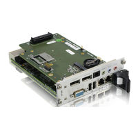
Kontron CP308 User Manual (170 pages)
3U CompactPCI Processor Board based on the Intel Core 2 Duo Processor with the Mobile Intel GS45 Express Chipset
Brand:
Kontron
| Category:
Computer Hardware
| Size: 1.41 MB
Table of Contents
Revision History
2
Imprint
2
Disclaimer
2
Table of Contents
3
List of Tables
11
List of Figures
15
Proprietary Note
17
Trademarks
17
Environmental Protection Statement
17
Explanation of Symbols
18
For Your Safety
19
High Voltage Safety Instructions
19
Special Handling and Unpacking Instructions
19
General Instructions on Usage
20
Two Year Warranty
21
1 Introduction
23
Board Overview
25
Board Introduction
25
Board-Specific Information
26
System Expansion Capabilities
27
CP308-HDD Module
27
CP308-MEDIA Module
27
CP-RIO3-04 Rear I/O Module
27
USB 2.0 NAND Flash Module
27
Board Diagrams
27
Functional Block Diagram
28
CP308 Functional Block Diagram
28
Front Panel
29
HP CP308 Front Panel
29
Board Layout
30
4HP CP308 Board Layout (Top View)
30
4HP CP308 Board Layout (Bottom View)
30
Technical Specification
31
Kontron Software Support
36
Standards
37
Related Publications
38
Additional Standards for Boards Ordered with Ruggedized Service
38
2 Functional Description
39
CPU, Memory and Chipset
41
Cpu
41
Processors Supported on the CP308
41
CPU Frequency in the Various Speedstep® Modes
42
Maximum Power Dissipation of the Processors (CPU Only)
42
Memory
43
Supported/Recommended Memory Configurations
43
Mobile Intel® GS45 Express Chipset Overview
44
I/O Controller Hub ICH9M-SFF
44
Intel® GS45 Graphics Memory Controller Hub
44
Peripherals
45
Timer
45
Watchdog Timer
45
Battery
45
Reset
46
SPI Flash for Uefi BIOS
46
USB 2.0 NAND Flash Module
47
8HP Expansion Modules
47
Integrated Trusted Platform Module (Itpm)
47
Board Interfaces
48
Front Panel Leds
48
Watchdog and Temperature Status Leds
48
Watchdog Status LED and Temperature Status LED Function
48
General Purpose LED Function
49
General Purpose Leds
49
Smc Led
50
DIP Switch SW1
50
POST Code Sequence
50
POST Code Example
50
DIP Switch SW1 Function
50
USB Interfaces
51
Front Panel USB Connectors J4 and J5
51
Graphics Controller
51
USB Connectors J4 and J5
51
USB Connectors J4 and J5 Pinout
51
D-Sub VGA Con. J3
52
D-Sub VGA Connector J3 Pinout
52
Graphics Memory Usage
52
Graphics Resolution
52
VGA Analog Interface and Connector J3
52
Gigabit Ethernet
53
Dual Gigabit Ethernet Connector J6A/B
53
Serial ATA Connectors J7 and J8
54
Compactpci Interface
54
Board Functionality When Installed in System Controller Slot
54
SATA Con. J7 and J8
54
SATA Connectors J7 and J8 Pinout
54
Board Functionality When Installed in Peripheral Slot (Passive Mode)
55
Board Insertion/Replacement under Power
55
ENUM# Interrupt
55
Front/Rear I/O Configuration
55
Power Ramping
55
Compactpci Connectors J1 and J2
56
Compactpci Connector Keying
56
Compactpci Bus Connector J1 System Controller Slot Pinout
57
Compactpci Connectors J1 and J2 Pinouts
57
Compactpci Bus Connector J1 Peripheral Slot Pinout
58
Optional Rear I/O Interface
60
Optional Rear I/O Interface on Compactpci Connector J2
61
Rear I/O Compactpci Bus Connector J2 Pinout (CP308 Rear I/O Vers.)
61
GPIO Signal Description
62
Rear I/O Configuration
63
System Management Controller
65
Sensors Implemented on the CP308
65
Processor and Chipset Sensors and Signals
65
Onboard Temperature Sensors
66
3 Installation
67
Safety Requirements
69
CP308 Initial Installation Procedures
70
Standard Removal Procedures
71
Insertion/Removal under Power
72
Replacement under Power in Peripheral Slot
72
Installation of CP308 Peripheral Devices
75
Connecting a Peripheral Device to the 4HP CP308
75
Connecting a Peripheral Device to the 8HP CP308 with CP308-HDD
75
Connecting a Peripheral Device to the 8HP CP308 with CP308-MEDIA
76
USB 2.0 NAND Flash Module Installation
76
USB Device Installation
76
Compactflash Card Installation
77
HDD/SSD Installation
77
Installation of External Serial ATA Devices
77
SD/SDHC Card Installation
77
Battery Replacement
78
PCI Express Mini Card Installation
78
Rear I/O Device Installation
78
Software Installation
79
4 Configuration
81
DIP Switch Configuration
83
DIP Switch SW1 Functionality
83
DIP Switch SW1
83
Jumper Description
84
Uefi BIOS Settings
84
Jumper for Clearing the Uefi BIOS Settings
84
I/O Address Map
85
CP308-Specific Registers
86
Status Register 0 (STAT0)
86
Status Register 1 (STAT1)
87
Control Register 0 (CTRL0)
87
Control Register 1 (CTRL1)
88
Device Protection Register (DPROT)
89
Reset Status Register (RSTAT)
90
Board Interrupt Configuration Register (BICFG)
91
Status Register 2 (STAT2)
92
Board ID Register (BID)
93
Board and PLD Revision Register (BREV)
93
Geographic Addressing Register (GEOAD)
93
Watchdog Timer Control Register (WTIM)
94
Watchdog Timer Control Register (WTIM)
95
LED Configuration Register (LCFG)
96
LED Control Register (LCTRL)
97
General Purpose Output Register (GPOUT)
98
General Purpose Input Register (GPIN)
99
SMC-Specific Registers
100
SMC Controller Status Register 0 (ICSTA0)
100
SMC Controller Status Register 1 (ICSTA1)
101
SMC Keyboard Controller-Style Interface
101
5 Power Considerations
103
System Power
105
CP308 Baseboard
105
Maximum Input Power Voltage Limits
105
DC Operational Input Voltage Ranges
105
Backplane
106
Power Supply Units
106
Power-Up Sequence
106
Start-Up Requirement
106
Input Voltage Characteristics
107
Regulation
107
Tolerance
107
Power Consumption
108
Power Consumption: CP308 in EFI Shell Mode
109
Power Consumption: CP308 with Linux® / Win.® XP in IDLE Mode
109
Power Consumption: CP308 with Linux®/Windows® XP, Memory Test
109
Power Consumption of CP308 Accessories
110
Start-Up Currents of the CP308
110
STDBY Currents During Main Power-Off
110
6 Thermal Considerations
111
Board Internal Thermal Monitoring
113
Placement of the Temperature Sensors
113
Temperature Sensor Placement (CP308 Top View)
113
Processor Thermal Monitoring and Regulation
114
Digital Thermal Sensor (DTS)
114
Thermal Diode Sensor
114
Thermal Monitor 1 (TM1)
114
Thermal Monitor 2 (TM2)
115
TM1 and TM2 Operation
115
Catastrophic Cooling Failure Sensor
115
Chipset Thermal Monitor
116
Internal Thermal Sensors
116
External Thermal Sensors
116
Catastrophic Trip Point Thermtrip
116
External Thermal Regulation
117
Operational Limits for the CP308
119
Operational Limits for the CP308 with Core™2 Duo 1.2 Ghz
119
Operational Limits for the CP308 with Core™2 Duo 1.86 Ghz
119
Peripherals
120
Operational Limits for the CP308 with Core™2 Duo 2.26 Ghz
120
CP308-HDD Module
123
Overview
123
Technical Specifications
124
CP308-HDD Module Specifications
124
CP308-HDD Module Functional Block Diagram
125
Front Panel of the 8HP CP308 with CP308-HDD Module
126
CP308-HDD Module Layout
127
Module Interfaces (Front Panel and Onboard)
128
Keyboard/Mouse Interface
128
Universal Serial Port
129
Keyboard/Mouse Connector J4
129
Serial Port Connector J5
129
USB Interfaces
130
A.6.3 USB Interfaces
130
USB 2.0 NAND Flash Module
130
USB Connectors J2 and J3 Pinout
130
USB Connectors J2 and J3
130
DVI-D Interface
131
DVI-D Connector J1 Pinout
131
DVI-D Connector J1
131
A.6.5 DVI-D Interface
131
Compactflash Card Socket
132
Compactflash Connector J9 Pinout
132
Compactflash Connector J9
132
SATA Interface
133
SATA Connector J7 Pinout
133
A.6.7 SATA Interface
133
Battery
134
A.6.8 Battery
134
CP308-MEDIA Module
137
Overview
137
Technical Specifications
138
CP308-MEDIA Module Specifications
138
CP308-MEDIA Module Functional Block Diagram
140
Front Panel of the 8HP CP308 with CP308-MEDIA Module
141
CP308-MEDIA Module Layout
142
CP308-MEDIA Module Layout (Top View)
142
CP308-MEDIA Module Layout (Bottom View)
142
Module Interfaces (Front Panel and Onboard)
143
Displayport Interfaces
143
Displayport Connectors J2 and J4 Pinout
143
Displayport Connectors J2 and J4
143
B.6.1 Displayport Interfaces
143
Audio Output Interface Configuration
144
HD Audio Interfaces
145
B.6.2 HD Audio Interfaces
145
B.6.2.1 HD Audio Specifications
145
HD Audio Specifications
145
MIC-In, Line-In and Line-Out Interfaces
146
Triple Audio Jack J8
146
B.6.2.4 CD-In Interface
147
B.6.2.5 Internal Line-Out Mono Interface
147
CD-In Connector J9
147
CD-In Connector J9 Pinout
147
CD-In Interface
147
Internal Line-Out Mono Connector J10
147
Internal Line-Out Mono Connector J10 Pinout
147
Internal Line-Out Mono Interface
147
S/P-DIF-Out Connector J6
147
S/P-DIF-Out Interface
147
COM Interface
148
B.6.3 COM Interface
148
PCI Express Mini Card Socket
148
Serial Port Connector J1 (COM1) Pinout
148
Serial Port Connector J1 (COM1)
148
PCI Express Mini Card Connector J5 Pinout
149
PCI Express Mini Card Connector J5
149
SDHC Interface
150
SD/SDHC Card Socket J3 Pinout
150
SD/SDHC Card Socket J3
150
B.6.5 SDHC Interface
150
SATA Interface
151
SATA Connector J7
151
B.6.6 SATA Interface
151
Compactflash Card Socket
152
Compactflash Connector J9 Pinout
152
Compactflash Connector J13
152
Battery
153
B.6.8 Battery
153
CP-RIO3-04 Rear I/O Module
157
Overview
157
Technical Specifications
158
CP-RIO3-04 Rear I/O Module Main Specifications
158
Front Panels
159
CP-RIO3-04 Front Panels, 4HP and 8HP Versions
159
Module Layout: 4HP and 8HP Versions
160
CP-RIO3-04 Rear I/O Module Layout, 4HP Version
160
CP-RIO3-04 Rear I/O Module Layout, 8HP Version
160
Module Interfaces
161
USB Interfaces
161
USB Connectors J11 and J12 Pinout
161
C.5.1 USB Interfaces
161
VGA Interface
162
D-Sub VGA Connector J7 Pinout
162
D-Sub VGA Connector J7
162
C.5.2 VGA Interface
162
Gigabit Ethernet Interface
163
COM Interface
164
COM Connectors J2A (COM1) and J3A (COM2) Pinout
164
Serial Port Connectors J2 (COM1) and J3 (COM2) Pinout
164
COM Connectors J2A (COM1) and J3A (COM2)
164
Serial Port Connectors J2 (COM1) and J3 (COM2)
164
C.5.4 COM Interface
164
Peripheral Control Interface
165
Peripheral Con. J13
165
Serial ATA Interfaces SATA4 and SATA5
166
SATA Connectors J5 and J6 Pinout
166
Rear I/O Interface on Compactpci Connector Rj2
167
Rear I/O Compactpci Connector Rj2
168
Advertisement
Advertisement
Related Products
Kontron CP3002-RA
Kontron CP3002-RC
Kontron CP3003-SA
Kontron CP3003-V
Kontron CP3002
Kontron CP3005-SA
Kontron CP3-BP4-M
Kontron CP3-BP6-ATX
Kontron CP3-BP11-P47
Kontron CP3-BP11-M
Kontron Categories
Computer Hardware
Motherboard
Server
Desktop
PCI Card
More Kontron Manuals
Login
Sign In
OR
Sign in with Facebook
Sign in with Google
Upload manual
Upload from disk
Upload from URL