Sign In
Upload
Manuals
Brands
Comtech EF Data Manuals
Modem
CDM-600L
Comtech EF Data CDM-600L Manuals
Manuals and User Guides for Comtech EF Data CDM-600L. We have
2
Comtech EF Data CDM-600L manuals available for free PDF download: Installation And Operation Manual
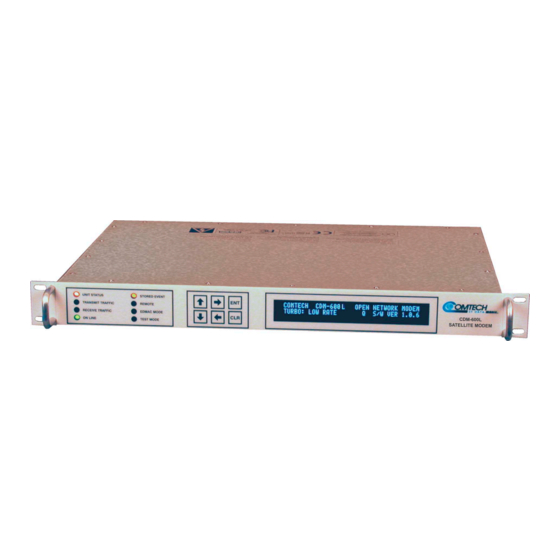
Comtech EF Data CDM-600L Installation And Operation Manual (248 pages)
Open Network Satellite Modem (2.4 kbps – 20 Mbps)
Brand:
Comtech EF Data
| Category:
Modem
| Size: 8.22 MB
Table of Contents
Installation and Operation Manual
1
Table of Contents
11
About this Manual
17
Conventions and References
17
Electrical Safety
18
Recommended Standard Designations
18
Emc (Electromagnetic Compatibility)
20
Telecommunications Terminal Equipment Directive
20
Limitations of Warranty
22
Warranty Policy
22
Chapter 1. Introduction
23
Figure 1-1. CDM-600L L-Band Satellite Modem
23
Standard Features
24
Aupc
24
Software - Flash Upgrading
24
Verification
25
Data Interfaces
25
Major Assemblies
25
Fast Options and Hardware Options
26
FAST Accessible Options
27
FAST System Theory
27
Implementation
28
Hardware Options
28
Supporting Hardware and Software
29
Compatibility
29
New in this Release
29
Chapter 2. Installation
31
Unpacking
31
Mounting
32
Figure 2-1. Installation of the Optional Mounting Bracket, KT/6228-2
33
Configuration
34
Select Internal if Loop
34
Connect External Cables
34
Chapter 3. Functional Description
35
Figure 3-1. CDM-600L Modem Block Diagram
36
Chapter 4. Physical Description
37
Introduction
37
Front Panel
37
Figure 4-1. CDM-600L Front Panel
37
Rear Panel
38
Figure 4-2. CDM-600L Rear Panel
38
Dimensional Envelope
42
Figure 4-3. CDM-600L Dimensional Envelope
42
Chapter 5. Connector Pinouts
43
Connector Overview
43
Table 5-1. CDM-600L External Connections
44
Overhead Interface Connector (P3A)
45
Table 5-2. Overhead Interface Connector Pin Assignments
45
Data Interface Connector (P3B)
46
Table 5-3. Data Interface Connector Pin Assignments
46
Audio Interface Connector (P4A)
47
Remote Control Interface Connector (P4B)
47
Table 5-4. Audio Interface Connector Pin Assignments
47
Table 5-5. Remote Control Interface Connector Pin Assignments
47
Idr Backward Alarms Connector (P5A)
48
Auxiliary Serial Connector (P6)
48
Table 5-6. IDR Alarm Interface Connector Pin Assignments
48
Table 5-7. Auxiliary Serial Connector (USB Type B Socket)
48
Balanced G.703 Interface Connector (P7)
49
Bnc Connectors
49
Table 5-8. Balanced G.703 Interface Connector Pin Assignments
49
Table 5-9. BNC Connectors
49
Unit Alarms (P5B)
50
Ac Power Connector Option
50
Table 5-10. Alarm Interface Connector Pin Assignments
50
DC Power Connector Option
51
Ground Connector
51
Chapter 6. Front Panel Operation
53
Description
53
Figure 6-1. Front Panel View
53
Table 6-1. Front Panel LED Indicators
54
Figure 6-2. Keypad
55
Figure 6-3. CDM-600L Menu Trees
56
Opening Screen
57
Main Menu
57
Config
58
Chapter 10. Clock Modes and Drop and Insert (D&I)
72
Test
80
Figure 6-4. Loopback Modes
81
Information
82
Monitor
86
Store/Load
91
Utilities
92
Odu
94
Fast
98
Chapter 7. Forward Error Correction Options
99
Introduction
99
Viterbi
99
Sequential
100
Table 7-1. Viterbi Decoding Summary
100
Reed-Solomon Outer Codec
101
Table 7-2. Sequential Decoding Summary
101
Table 7-3. Concatenated Reed-Solomon Coding Summary
102
Closed Network Modes
102
Trellis Coding (Fast Option)
103
Table 7-4. 8-PSK/TCM Coding Summary
103
Turbo Product Codec (Hardware Option)
104
Tpc and Low Density Parity Check (Ldpc) Coding
104
Introduction
104
LDPC Versus TPC
105
Table 7-5. Available TPC and LDPC Modes
106
7.7.3 End-To-End Processing Delay
107
Table 7-6. Turbo Product Coding Processing Delay Comparison
107
Uncoded Operation (no Fec)
109
Table 7-7. TPC and LDPC Summary
109
Figure 7-1. Viterbi Decoding
111
Figure 7-2. Sequential Decoding 64 Kbps
112
Figure 7-3. Sequential Decoding 1024 Kbps
113
Figure 7-4. Sequential Decoding 2048 Kbps
114
Figure 7-7. 8-PSK/TCM Rate 2/3 with and Without Concatenated Reed-Solomon Outer Code
117
Figure 7-8. Comtech EF Data Turbo Product Codec Rate 3/4 QPSK/OQPSK, 8-PSK and 16-QAM
118
Figure 7-9. Comtech EF Data Turbo Product Codec Rate 7/8 QPSK/OQPSK, 8-PSK and 16-QAM
119
Figure 7-10. Rate 1/2 QPSK, Rate 0.95 QPSK and Rate 0.95 8-PSK
120
Figure 7-11. Rate 21/44 BPSK and Rate 5/16 BPSK Turbo
121
Figure 7-12. 16-QAM Viterbi, Rate 3/4 and Rate 7/8 with 220,200 Reed-Solomon Outer Code
122
Figure 7-13. Differential Encoding - no FEC, no Scrambling
123
Figure 7-14. LDPC, Rate 1/2, BPSK, (O)QPSK
124
Figure 7-15. LDPC, Rate 2/3, (O)QPSK/8-PSK/8-QAM
125
Figure 7-16. LDPC, Rate 3/4, (O)QPSK/8-QAM
126
Figure 7-17. LDPC, Rate 3/4, 8-PSK / 8-QAM
127
Chapter 8. Offset Qpsk Operation
129
Chapter 9. Open Network Operations
131
Introduction
131
Ibs
131
IBS Clock/Data Recovery and De-Jitter
132
IBS Framing
132
IBS Engineering Service Channel
132
IBS Scrambling
132
Drop and Insert
132
D&I Primary Data Interfaces
133
D&I Framing
133
Idr
134
IDR Primary Data Interfaces
135
IDR Engineering Service Channel
135
Transmit Clocking
137
Internal Clock
137
TX Terrestrial Clock
138
RX Loop-Timed, RX=TX
138
RX Loop-Timed, RX<>TX (Asymmetric Loop Timing)
138
External Clock
138
External Reference
139
Receive Clocking
139
Buffer Disabled (RX Satellite)
139
Buffer Enabled, TX=RX (TX Terrestrial or External Clock)
139
Buffer Enabled, RX<>TX (TX Terrestrial or External Clock)
139
X.21 Notes
139
Figure 10-1 Tx Clock Modes
140
Figure 10-2 Rx Clock Modes
141
Drop and Insert
142
Frame Formats
142
Figure 10-3 Supported T1 and E1 Framing Formats
142
Time Slot Selection
143
Drop and Insert Clocking
144
Figure 10-4 Drop and Insert Clocking
144
Rx Buffer Clock = Insert (D&I Only)
145
Single-Source Multiple Modems
145
Figure 10-5. Single-Source Multiple Modems (Looming)
146
Chapter 11. Edmac Channel
147
Theory of Operation
147
M&C Connection
148
Setup Summary
149
Drop & Insert
150
Chapter 12. Automatic Uplink Power Control
151
Introduction
151
Setting Aupc Parameters
152
AUPC Target Eb/No
152
Max Range, AUPC
152
Alarm, AUPC
153
Demod Unlock
153
Compensation Rate
153
Monitoring
154
Chapter 13. Esc
155
Introduction
155
Overhead Details
155
Available Baud Rates
156
Configuration
156
Effect on Eb/No Performance
156
Chapter 14. Flash Upgrading
157
Chapter 15. Summary of Specifications
159
Modulator
159
Demodulator
162
Automatic Uplink Power Control
167
Data Interfaces
167
Data Rate Ranges
168
Framing Summary
169
Miscellaneous
169
Approvals
170
Chapter 16. Remote Control
171
Introduction
171
Rs-485
171
Rs-232
172
Basic Protocol
172
Packet Structure
173
Start of Packet
173
Address
173
Instruction Code
174
Instruction Code Qualifier
174
Message Arguments
175
End of Packet
175
Remote Commands
176
TX Remote Commands
177
RX Remote Commands
183
Unit Remote Commands
190
Query Commands
197
Bulk Commands
203
BUC Commands
206
LNB Commands
209
Chapter 17. Buc Fsk Communications
211
Introduction
211
Transmission Interface
212
Message Structure
212
Command Message Structure (CDM-600L to BUC)
212
Response Message Structure (BUC to CDM-600L)
213
Buc Power Class
213
Buc Output Power Leveling
214
Chapter 18. Dst Setup
217
Initial Operation
217
Prior to Turning on Power
217
Initial Power up - Modem Only
218
Lo, MIX and Spectrum (Inversion) Settings
219
Applying Power to the Buc
220
Initial Operation of the Modem with the Buc and Lnb
221
Appendix A. Cable Drawings
223
Appendix B. Eb/No Measurement
227
Appendix C. Fast Activation Procedure
231
Introduction
231
Activation Procedure
231
Serial Number
231
C.1 Introduction
231
C.2 Activation Procedure
231
C.2.1 Serial Number
231
View Currently Installed Features
232
Enter Access Codes
232
Index
233
Installation Instructions
241
Front Panel Operation
242
Remote Control
244
Metric Conversions
247
Advertisement
Comtech EF Data CDM-600L Installation And Operation Manual (206 pages)
Open Network Satellite Modem 2.4 kbps – 20 Mbps
Brand:
Comtech EF Data
| Category:
Modem
| Size: 4.59 MB
Table of Contents
Table of Contents
7
Chapter 1. Introduction
19
Figure 1-1. CDM-600L
19
Standard Features
20
Aupc
20
Software - Flash Upgrading
20
Verification
21
Data Interfaces
21
Major Assemblies
21
Fast Options and Hardware Options
22
FAST Accessible Options
23
FAST System Theory
23
Implementation
23
Hardware Options
23
Supporting Hardware and Software
24
Compatibility
24
Chapter 2. Installation
25
Unpacking
25
Mounting
26
Figure 2-1. Installation of the Optional Mounting Bracket, KT/6228-2
27
Configuration
28
Select Internal if Loop
28
Connect External Cables
28
Chapter 3. Functional Description
29
Figure 3-1. CDM-600L Modem Block Diagram
30
Chapter 4. Physical Description
31
Introduction
31
Front Panel
31
Rear Panel
32
Dimensional Envelope
36
Chapter 5. Connector Pinouts
37
Connector Overview
37
Overhead Interface Connector (P3A)
39
Table 5-2. Overhead Interface Connector Pin Assignments
39
Data Interface Connector (P3B)
40
Table 5-3. Data Interface Connector Pin Assignments
40
Audio Interface Connector (P4A)
41
Remote Control Interface Connector (P4B)
41
Table 5-4. Audio Interface Connector Pin Assignments
41
Table 5-5. Remote Control Interface Connector Pin Assignments
41
Idr Backward Alarms Connector (P5A)
42
Auxiliary Serial Connector (P6)
42
Table 5-6. IDR Alarm Interface Connector Pin Assignments
42
Table 5-7. Auxiliary Serial Connector (USB Type B Socket)
42
Balanced G.703 Interface Connector (P7)
43
Bnc Connectors
43
Table 5-8. Balanced G.703 Interface Connector Pin Assignments
43
Table 5-9. BNC Connectors
43
Unit Alarms (P5B)
44
Ac Power Connector
44
Table 5-10. Alarm Interface Connector Pin Assignments
44
Ground Connector
45
Chapter 6. Front Panel Operation
47
Description
47
Figure 6-1. Front Panel View
47
Table 6-1. Front Panel LED Indicators
48
Figure 6-2. Keypad
49
Opening Screen
51
Main Menu
51
Config
52
Test
73
Figure 6-4. Loopback Modes
74
Information
75
Monitor
79
Store/Load
82
Buc
82
Fast
88
Chapter 7. Forward Error Correction Options
91
Introduction
91
Viterbi
91
Sequential
92
Table 7-1. Viterbi Decoding Summary
92
Reed-Solomon Outer Codec
93
Table 7-2. Sequential Decoding Summary
93
Table 7-3. Concatenated RS Coding Summary
94
Trellis Coding (Fast Option)
95
Table 7-4. 8-PSK/TCM Coding Summary
95
Turbo Product Codec (Hardware Option)
96
Introduction
96
The Evolution of TPC in Comtech Products
96
End-To-End Processing Delay
97
Table 7-5. Available TPC Modes
97
Table 7-6. Turbo Product Coding Processing Delay Comparison
97
Comparison of All TPC Modes
98
Uncoded Operation (no Fec)
99
Table 7-7. Turbo Product Coding Summary
99
Figure 7-2. Sequential Decoding 64 Kbps
102
Figure 7-5. Viterbi with Concatenated R-S Outer Code
105
Figure 7-6. Sequential with Concatenated R-S Outer Code
106
Figure 7-7. 8-PSK/TCM Rate 2/3 with and Without Concatenated R-S Outer Code
107
Figure 7-8. Comtech EF Data Turbo Product Codec Rate 3/4 QPSK/OQPSK, 8-PSK and 16-QAM
108
Figure 7-9. Comtech EF Data Turbo Product Codec Rate 7/8 QPSK/OQPSK, 8-PSK and 16-QAM
109
Figure 7-10. Rate 1/2 QPSK, Rate 0.95 QPSK and Rate 0.95 8-PSK
110
Figure 7-11. Rate 21/44 BPSK and Rate 5/16 BPSK Turbo
111
Figure 7-12. 16QAM Viterbi, Rate 3/4 and Rate 7/8 with 220,200 RS Outer Code
112
Figure 7-13. Differential Encoding - no FEC, no Scrambling
113
Chapter 8. Offset Qpsk Operation
115
Chapter 9 . Open Network Operations
117
Introduction
117
IBS Clock/Data Recovery and De-Jitter
118
IBS Framing
118
IBS Engineering Service Channel
118
IBS Scrambling
118
Drop and Insert
118
D&I Primary Data Interfaces
119
D&I Framing
119
Idr
120
IDR Primary Data Interfaces
121
IDR Engineering Service Channel
121
Chapter 10 . Clock Modes and Drop and Insert (D&I)
123
Transmit Clocking
123
Internal Clock
123
Tx Terrestrial
124
Rx Loop-Timed, RX=TX
124
Rx Loop-Timed, RX<>TX (Asymmetric Loop Timing)
124
External Clock
124
External Reference
125
Receive Clocking
125
Buffer Disabled (RX Satellite)
125
Buffer Enabled, TX=RX (TX Terrestrial or External Reference)
125
Buffer Enabled, RX<>TX (TX Terrestrial or External Reference)
125
X.21 Notes
125
Figure 10-1 Tx Clock Modes
126
Figure 10-2 Rx Clock Modes
127
Drop and Insert
128
Frame Formats
128
Figure 10-3 Supported T1 and E1 Framing Formats
128
Time Slot Selection
129
Drop and Insert Clocking
129
Figure 10-4 Drop and Insert Clocking
129
Rx Buffer Clock = Insert (D&I Only)
130
Chapter 11. Edmac Channel
131
Theory of Operation
131
M&C Connection
132
Setup Summary
133
Chapter 12. Automatic Uplink Power Control
135
Introduction
135
Setting Aupc Parameters
136
Target Eb/No
136
Max Range
136
Alarm
137
Demod Unlock
137
Compensation Rate
137
Monitoring
138
Chapter 13. Flash Upgrading
139
Chapter 14. Summary of Specifications
141
Modulator
141
Demodulator
144
Data Interfaces
149
Automatic Uplink Power Control
149
Data Rate Ranges
150
Framing Summary
151
Miscellaneous
151
Approvals
151
Chapter 15. Remote Control
153
Introduction
153
Basic Protocol
154
Packet Structure
155
Start of Packet
155
Address
155
Instruction Code
156
Instruction Code Qualifier
156
Message Arguments
158
End of Packet
158
Chapter 16. Buc Fsk Communications
189
Introduction
189
Message Structure
190
Command Message Structure (CDM-600L to BUC)
190
Response Message Structure (BUC to CDM-600L)
191
Power Class
191
Buc Output Power Leveling
192
Chapter 17. Dst Setup
195
Initial Operation
195
Prior to Turning on Power
195
Initial Power up - Modem Only
196
Applying Power to the Buc
198
Initial Operation of the Modem with the Buc and Lnb
199
Index
201
Advertisement
Related Products
Comtech EF Data CDM-600
Comtech EF Data CDM-625
Comtech EF Data CDM-625A
Comtech EF Data CDM-Qx
Comtech EF Data CDM-500
Comtech EF Data CDM-710L
Comtech EF Data Vipersat CDM-570L
Comtech EF Data CDM-2020
Comtech EF Data CDM-550
Comtech EF Data CDM-550T
Comtech EF Data Categories
Modem
Switch
Amplifier
Network Router
Media Converter
More Comtech EF Data Manuals
Login
Sign In
OR
Sign in with Facebook
Sign in with Google
Upload manual
Upload from disk
Upload from URL